
Product Specification
Page 2
... the presented subject matter. Intel, Core, Pentium, and Xeon are available on the absence or characteristics of Intel Corporation in this document, or other intellectual property rights. Changes to only the standard Intel® Desktop Board DH57DD with BIOS identifier JGIBX10J.86A. INFORMATION IN... THIS DOCUMENT IS PROVIDED IN CONNECTION WITH INTEL® PRODUCTS. NO LICENSE, EXPRESS OR IMPLIED, BY ESTOPPEL OR OTHERWISE,...
... the presented subject matter. Intel, Core, Pentium, and Xeon are available on the absence or characteristics of Intel Corporation in this document, or other intellectual property rights. Changes to only the standard Intel® Desktop Board DH57DD with BIOS identifier JGIBX10J.86A. INFORMATION IN... THIS DOCUMENT IS PROVIDED IN CONNECTION WITH INTEL® PRODUCTS. NO LICENSE, EXPRESS OR IMPLIED, BY ESTOPPEL OR OTHERWISE,...
Product Specification
Page 3
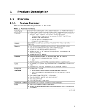
... is intended to provide detailed, technical information about the conventions used on the Intel Desktop Board DH57DD A map of the resources of the Intel Desktop Board The features supported by the BIOS Setup program A description of the BIOS error messages, beep codes, and POST codes Regulatory compliance and battery disposal information Typographical Conventions This section...
... is intended to provide detailed, technical information about the conventions used on the Intel Desktop Board DH57DD A map of the resources of the Intel Desktop Board The features supported by the BIOS Setup program A description of the BIOS error messages, beep codes, and POST codes Regulatory compliance and battery disposal information Typographical Conventions This section...
Product Specification
Page 6
Intel Desktop Board DH57DD Technical Product Specification 2.4.1 Form Factor 53 2.5 Electrical Considerations 54 2.5.1 Power Supply Considerations 54 2.5.2 Fan Header Current Capability 55 2.5.3 Add-in Board Considerations 55 2.6 Thermal Considerations 56 2.7 Reliability 59 2.8 Environmental 59 3 Overview of BIOS Features 3.1 Introduction 61 3.2 System Management BIOS (SMBIOS 63 3.3 Legacy USB Support 63 3.4 BIOS Updates 64 3.4.1 Language Support 64 3.4.2 Custom...
Intel Desktop Board DH57DD Technical Product Specification 2.4.1 Form Factor 53 2.5 Electrical Considerations 54 2.5.1 Power Supply Considerations 54 2.5.2 Fan Header Current Capability 55 2.5.3 Add-in Board Considerations 55 2.6 Thermal Considerations 56 2.7 Reliability 59 2.8 Environmental 59 3 Overview of BIOS Features 3.1 Introduction 61 3.2 System Management BIOS (SMBIOS 63 3.3 Legacy USB Support 63 3.4 BIOS Updates 64 3.4.1 Language Support 64 3.4.2 Custom...
Product Specification
Page 8
...Device Menu Options 66 41. Port 80h POST Codes 72 47. Safety Standards 77 49. Front Panel Header 48 29. States for BIOS Recovery 65 40. Environmental Specifications 59 37. Port 80h POST Code Ranges 71 46. Front-panel Power LED Blink Codes 70 44.... Typical Port 80h POST Sequence 75 48. Intel Desktop Board DH57DD Technical Product Specification 28. Supervisor and User Password Functions 67 42. BIOS Setup Configuration Jumper Settings 52 32. Tcontrol Values for Components 58 35. Thermal Considerations for ...
...Device Menu Options 66 41. Port 80h POST Codes 72 47. Safety Standards 77 49. Front Panel Header 48 29. States for BIOS Recovery 65 40. Environmental Specifications 59 37. Port 80h POST Code Ranges 71 46. Front-panel Power LED Blink Codes 70 44.... Typical Port 80h POST Sequence 75 48. Intel Desktop Board DH57DD Technical Product Specification 28. Supervisor and User Password Functions 67 42. BIOS Setup Configuration Jumper Settings 52 32. Tcontrol Values for Components 58 35. Thermal Considerations for ...
Product Specification
Page 9
...; One serial port header • Two front panel IEEE 1394a ports Legacy I/O Control BIOS Nuvoton W83677i Super I/O controller for serial port support • Intel® BIOS resident in an LGA1156 socket: ― Integrated graphics processing (processors with Intel® High Definition Graphics (Intel® HD Graphics)) ― External graphics interface controller ― Integrated memory controller...
...; One serial port header • Two front panel IEEE 1394a ports Legacy I/O Control BIOS Nuvoton W83677i Super I/O controller for serial port support • Intel® BIOS resident in an LGA1156 socket: ― Integrated graphics processing (processors with Intel® High Definition Graphics (Intel® HD Graphics)) ― External graphics interface controller ― Integrated memory controller...
Product Specification
Page 12
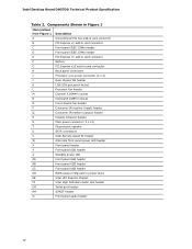
Intel Desktop Board DH57DD Technical Product Specification Table 2. Components Shown in Figure 1...IR emitter (output) header R Chassis intrusion header S Main power connector (2 x 12) T Piezoelectric speaker U SATA connectors V Intel Remote Assist PC header W Alternate front panel power LED header X Front panel header Y Front panel USB header Z Standby power...header BB Front panel USB header CC Front panel USB header DD BIOS setup configuration jumper block EE Intel H57 Express Chipset FF Intel High Definition Audio Link header GG Serial port header HH S/PDIF ...
Intel Desktop Board DH57DD Technical Product Specification Table 2. Components Shown in Figure 1...IR emitter (output) header R Chassis intrusion header S Main power connector (2 x 12) T Piezoelectric speaker U SATA connectors V Intel Remote Assist PC header W Alternate front panel power LED header X Front panel header Y Front panel USB header Z Standby power...header BB Front panel USB header CC Front panel USB header DD BIOS setup configuration jumper block EE Intel H57 Express Chipset FF Intel High Definition Audio Link header GG Serial port header HH S/PDIF ...
Product Specification
Page 14
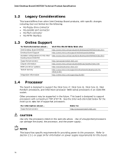
... up-to-date list of unsupported processors can damage the board, the processor, and the power supply. See the Intel web site listed below for the Intel Desktop Board DH57DD Supported processors Chipset information BIOS and driver updates Tested memory Integration information Visit this board. 14 Use of supported processors. This board is designed...
... up-to-date list of unsupported processors can damage the board, the processor, and the power supply. See the Intel web site listed below for the Intel Desktop Board DH57DD Supported processors Chipset information BIOS and driver updates Tested memory Integration information Visit this board. 14 Use of supported processors. This board is designed...
Product Specification
Page 15
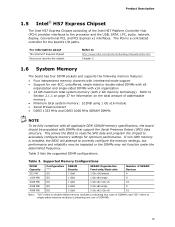
... may be populated with 2 Gb memory technology). Table 3. Table 3 lists the supported DIMM configurations. Product Description 1.5 Intel® H57 Express Chipset The Intel H57 Express Chipset consisting of SDRAM). 15 The PCH is installed, the BIOS will attempt to the processor and the USB, SATA, LPC, audio, network, display, Conventional PCI, and PCI...
... may be populated with 2 Gb memory technology). Table 3. Table 3 lists the supported DIMM configurations. Product Description 1.5 Intel® H57 Express Chipset The Intel H57 Express Chipset consisting of SDRAM). 15 The PCH is installed, the BIOS will attempt to the processor and the USB, SATA, LPC, audio, network, display, Conventional PCI, and PCI...
Product Specification
Page 20
... One front panel CIR receiver header The BIOS Setup program provides configuration options for configurations using the Windows* XP, Windows Vista*, and Windows 7* operating systems. For more information, see: http://www.serialata.org/. Intel Desktop Board DH57DD Technical Product Specification For information about The ...through the PCH, which supports a master/slave configuration and two devices per channel. The PCH provides independent SATA ports with BIOS support. For information about The location of the SATA connectors Refer to Figure 10, page 41 20 The underlying SATA ...
... One front panel CIR receiver header The BIOS Setup program provides configuration options for configurations using the Windows* XP, Windows Vista*, and Windows 7* operating systems. For more information, see: http://www.serialata.org/. Intel Desktop Board DH57DD Technical Product Specification For information about The ...through the PCH, which supports a master/slave configuration and two devices per channel. The PCH provides independent SATA ports with BIOS support. For information about The location of the SATA connectors Refer to Figure 10, page 41 20 The underlying SATA ...
Product Specification
Page 25
... detection • Thermal monitoring 1.14.1 Hardware Monitoring and Fan Control The features of the hardware monitoring and fan control include: • Intel Quiet System Technology, delivering acoustically-optimized thermal management • Thermal sensors in the processor and PCH, as well as needed 25 Figure 1...battery. 1.14 Hardware Management Subsystem The hardware management features enable the board to detect levels above or below a certain level, the BIOS Setup program settings stored in , the standby current from the power supply extends the life of three years. NOTE If the ...
... detection • Thermal monitoring 1.14.1 Hardware Monitoring and Fan Control The features of the hardware monitoring and fan control include: • Intel Quiet System Technology, delivering acoustically-optimized thermal management • Thermal sensors in the processor and PCH, as well as needed 25 Figure 1...battery. 1.14 Hardware Management Subsystem The hardware management features enable the board to detect levels above or below a certain level, the BIOS Setup program settings stored in , the standby current from the power supply extends the life of three years. NOTE If the ...
Product Specification
Page 26
Intel Desktop Board DH57DD Technical Product Specification 1.14.2 Fan Monitoring Fan monitoring can be observed through the BIOS setup user interface, Intel® Desktop Utilities, or third-party software. The security feature uses a mechanical switch on the chassis that detects if the chassis cover is in the ...
Intel Desktop Board DH57DD Technical Product Specification 1.14.2 Fan Monitoring Fan monitoring can be observed through the BIOS setup user interface, Intel® Desktop Utilities, or third-party software. The security feature uses a mechanical switch on the chassis that detects if the chassis cover is in the ...
Product Specification
Page 31
... supply removes all non-standby voltages. Failure to do so can be set using the Last Power State feature in before power was in the BIOS Setup program's Boot menu. Product Description 1.15.2 Hardware Support CAUTION Ensure that provides full ACPI support. 1.15.2.1 Power Connector ATX12V-compliant power supplies can turn...
... supply removes all non-standby voltages. Failure to do so can be set using the Last Power State feature in before power was in the BIOS Setup program's Boot menu. Product Description 1.15.2 Hardware Support CAUTION Ensure that provides full ACPI support. 1.15.2.1 Power Connector ATX12V-compliant power supplies can turn...

Product Specification
Page 33
... system quickly returns to provide adequate standby current when implementing Instantly Available PC technology can wake the computer from USB and is supported by the BIOS "S3 State Indicator" option). When signaled by a wake-up Support When the WAKE# signal on page 30 lists the devices and events that can damage...
... system quickly returns to provide adequate standby current when implementing Instantly Available PC technology can wake the computer from USB and is supported by the BIOS "S3 State Indicator" option). When signaled by a wake-up Support When the WAKE# signal on page 30 lists the devices and events that can damage...
Product Specification
Page 37
... map. 2 Technical Reference 2.1 Memory Resources 2.1.1 Addressable Memory The board utilizes 16 GB of system addresses. 37 These functions include the following: • BIOS/SPI Flash device (64 Mbit) • Local APIC (19 MB) • Direct Media Interface (40 MB) • PCI Express configuration space (... system memory can be used when there is allocated for Conventional PCI bus and PCI Express add-in cards, PCI Express configuration space, BIOS (SPI Flash device), and chipset overhead resides above the 4 GB boundary. Figure 8 shows a schematic of DRAM (total system memory)....
... map. 2 Technical Reference 2.1 Memory Resources 2.1.1 Addressable Memory The board utilizes 16 GB of system addresses. 37 These functions include the following: • BIOS/SPI Flash device (64 Mbit) • Local APIC (19 MB) • Direct Media Interface (40 MB) • PCI Express configuration space (... system memory can be used when there is allocated for Conventional PCI bus and PCI Express add-in cards, PCI Express configuration space, BIOS (SPI Flash device), and chipset overhead resides above the 4 GB boundary. Figure 8 shows a schematic of DRAM (total system memory)....
Product Specification
Page 39
...9FBFF 00000 - 7FFFF Size 16382 MB 64 KB 64 KB 96 KB 160 KB 1 KB 127 KB 512 KB Description Extended memory Runtime BIOS Reserved Potential available high DOS memory (open to the computer, the power cable, and the external devices themselves. Table 11. Dependent on ...video adapter used. Video memory and BIOS Extended BIOS data (movable by the external devices could cause damage to the Conventional PCI bus). This section describes the board's connectors. Technical Reference...
...9FBFF 00000 - 7FFFF Size 16382 MB 64 KB 64 KB 96 KB 160 KB 1 KB 127 KB 512 KB Description Extended memory Runtime BIOS Reserved Potential available high DOS memory (open to the computer, the power cable, and the external devices themselves. Table 11. Dependent on ...video adapter used. Video memory and BIOS Extended BIOS data (movable by the external devices could cause damage to the Conventional PCI bus). This section describes the board's connectors. Technical Reference...

Product Specification
Page 49
... connected to a momentary single pole, single throw (SPST) type switch that is due to a front panel momentary-contact power switch. More options are available through BIOS setup. States for a One-Color Power LED LED State Description Off Power off/sleeping Steady Lit Running Blink Standby 2.2.2.4.4 Power Switch Header Pins 6 and 8 can...
... connected to a momentary single pole, single throw (SPST) type switch that is due to a front panel momentary-contact power switch. More options are available through BIOS setup. States for a One-Color Power LED LED State Description Off Power off/sleeping Steady Lit Running Blink Standby 2.2.2.4.4 Power Switch Header Pins 6 and 8 can...

Product Specification
Page 51
Figure 14. Figure 14 shows the location of the Jumper Block 51 Table 31 describes the jumper settings for the three modes: normal, configure, and recovery. Otherwise, the board could be damaged. Location of the jumper block. Always turn off the power and unplug the power cord from the computer before changing a jumper setting. The 3-pin jumper block determines the BIOS Setup program's mode. Technical Reference 2.3 Jumper Block CAUTION Do not move the jumper with the power on.
Figure 14. Figure 14 shows the location of the Jumper Block 51 Table 31 describes the jumper settings for the three modes: normal, configure, and recovery. Otherwise, the board could be damaged. Location of the jumper block. Always turn off the power and unplug the power cord from the computer before changing a jumper setting. The 3-pin jumper block determines the BIOS Setup program's mode. Technical Reference 2.3 Jumper Block CAUTION Do not move the jumper with the power on.

Product Specification
Page 52
... Jumper Settings Function/Mode Normal Jumper Setting 1-2 Configuration The BIOS uses current configuration information and passwords for booting. Configure 2-3 Recovery None After the POST runs, Setup runs automatically. The maintenance menu is required. 52... Note that this Configure mode is the only way to their default values. Press F9 (restore defaults) while in Configure mode to restore the BIOS/CMOS settings to clear the BIOS/CMOS settings. Intel Desktop Board DH57DD Technical Product Specification Table 31. A recovery CD or USB flash drive is displayed. The...
... Jumper Settings Function/Mode Normal Jumper Setting 1-2 Configuration The BIOS uses current configuration information and passwords for booting. Configure 2-3 Recovery None After the POST runs, Setup runs automatically. The maintenance menu is required. 52... Note that this Configure mode is the only way to their default values. Press F9 (restore defaults) while in Configure mode to restore the BIOS/CMOS settings to clear the BIOS/CMOS settings. Intel Desktop Board DH57DD Technical Product Specification Table 31. A recovery CD or USB flash drive is displayed. The...
Product Specification
Page 58
.... Tcontrol Values for Components Component Tcontrol Processor For processor case temperature, see processor datasheets and processor specification updates Intel H57 Express Chipset 111 oC To ensure functionality and reliability, the component is specified for proper operation when Case... temperature at or below the Maximum Case Temperature. Intel Desktop Board DH57DD Technical Product Specification Table 34 provides maximum case temperatures for the components that the temperature measurement in the system BIOS is dissipating less than TDP, the case temperature should...
.... Tcontrol Values for Components Component Tcontrol Processor For processor case temperature, see processor datasheets and processor specification updates Intel H57 Express Chipset 111 oC To ensure functionality and reliability, the component is specified for proper operation when Case... temperature at or below the Maximum Case Temperature. Intel Desktop Board DH57DD Technical Product Specification Table 34 provides maximum case temperatures for the components that the temperature measurement in the system BIOS is dissipating less than TDP, the case temperature should...
Product Specification
Page 61
...Performance Security Power Boot Exit NOTE The maintenance menu is displayed only when the board is shown below. 3 Overview of BIOS Features 3.1 Introduction The board uses an Intel BIOS that is accessed by pressing the key after the Power-On Self-Test (POST) memory test begins and before the... operating system boot begins. The BIOS Setup program is stored in Maintenance mode. The SPI Flash contains the BIOS Setup program, POST, LAN EEPROM...
...Performance Security Power Boot Exit NOTE The maintenance menu is displayed only when the board is shown below. 3 Overview of BIOS Features 3.1 Introduction The board uses an Intel BIOS that is accessed by pressing the key after the Power-On Self-Test (POST) memory test begins and before the... operating system boot begins. The BIOS Setup program is stored in Maintenance mode. The SPI Flash contains the BIOS Setup program, POST, LAN EEPROM...


