

Product Specification
Page 6
2.5.1 Power Supply Considerations 53 2.5.2 Fan Header Current Capability 54 2.5.3 Add-in Board Considerations 54 2.6 Thermal Considerations 54 2.7 Reliability 56 2.8 Environmental 57 3 Overview of BIOS Features 3.1 Introduction ...Configuration 65 3.9.2 BIOS Boot Optimizations 65 3.10 BIOS Security Features 66 4 Error Messages and Beep Codes 4.1 Speaker 67 4.2 BIOS Beep Codes 67 4.3 Front-panel Power LED Blink Codes 68 4.4 BIOS Error Messages 68 4.5 Port 80h POST Codes 69 5 Regulatory Compliance and Battery Disposal Information 5.1 Regulatory Compliance 75 5.1.1 Safety Standards ...
2.5.1 Power Supply Considerations 53 2.5.2 Fan Header Current Capability 54 2.5.3 Add-in Board Considerations 54 2.6 Thermal Considerations 54 2.7 Reliability 56 2.8 Environmental 57 3 Overview of BIOS Features 3.1 Introduction ...Configuration 65 3.9.2 BIOS Boot Optimizations 65 3.10 BIOS Security Features 66 4 Error Messages and Beep Codes 4.1 Speaker 67 4.2 BIOS Beep Codes 67 4.3 Front-panel Power LED Blink Codes 68 4.4 BIOS Error Messages 68 4.5 Port 80h POST Codes 69 5 Regulatory Compliance and Battery Disposal Information 5.1 Regulatory Compliance 75 5.1.1 Safety Standards ...
Product Specification
Page 7
...Port Header 44 14. Recommended Power Supply Current Values 53 27. Block Diagram 13 3. Audio Jack Support 23 5. Power States and Targeted System Power 30 8. Serial ATA Connectors 44 12. Processor Fan Header 44 16. Auxiliary Front Panel Power/Sleep LED Header 45 19. ... 5. Detailed System Memory Address Map 38 9. Connection Diagram for Intel® HD Audio 45 17. Localized High Temperature Zones 55 Tables 1. Board Dimensions 52 15. Contents Figures 1. Location of the Standby Power Indicator LED 35 8. Component-side Connectors and Headers Shown in ...
...Port Header 44 14. Recommended Power Supply Current Values 53 27. Block Diagram 13 3. Audio Jack Support 23 5. Power States and Targeted System Power 30 8. Serial ATA Connectors 44 12. Processor Fan Header 44 16. Auxiliary Front Panel Power/Sleep LED Header 45 19. ... 5. Detailed System Memory Address Map 38 9. Connection Diagram for Intel® HD Audio 45 17. Localized High Temperature Zones 55 Tables 1. Board Dimensions 52 15. Contents Figures 1. Location of the Standby Power Indicator LED 35 8. Component-side Connectors and Headers Shown in ...

Product Specification
Page 10
Intel Desktop Board DG41AN Technical Product Specification Table 1. Feature Summary (continued) Instantly Available PC Technology Expansion Capabilities Hardware Monitor Subsystem • Support for PCI* Local Bus Specification Revision 2.3 • ... PCI, LAN, serial port, front panel, PS/2 device, and USB ports • One Conventional PCI bus connector • Voltage sense to detect out of range power supply voltages • Thermal sense to detect out of range thermal values • Two fan headers • Two fan sense inputs used to monitor fan activity...
Intel Desktop Board DG41AN Technical Product Specification Table 1. Feature Summary (continued) Instantly Available PC Technology Expansion Capabilities Hardware Monitor Subsystem • Support for PCI* Local Bus Specification Revision 2.3 • ... PCI, LAN, serial port, front panel, PS/2 device, and USB ports • One Conventional PCI bus connector • Voltage sense to detect out of range power supply voltages • Thermal sense to detect out of range thermal values • Two fan headers • Two fan sense inputs used to monitor fan activity...

Product Specification
Page 14
...-date list of supported processors. Use of unsupported processors can damage the board, the processor, and the power supply. 14 This board is designed to : http://processormatch.intel.com CAUTION Use only the processors listed on the back panel • No diskette drive connector 1.3 Online ... port on the web site above are only supported when falling within the wattage requirements of the board. Intel Desktop Board DG41AN Technical Product Specification 1.2 Legacy Considerations This board differs from other Intel® Desktop Board products, with a maximum wattage of 65 W.
...-date list of supported processors. Use of unsupported processors can damage the board, the processor, and the power supply. 14 This board is designed to : http://processormatch.intel.com CAUTION Use only the processors listed on the back panel • No diskette drive connector 1.3 Online ... port on the web site above are only supported when falling within the wattage requirements of the board. Intel Desktop Board DG41AN Technical Product Specification 1.2 Legacy Considerations This board differs from other Intel® Desktop Board products, with a maximum wattage of 65 W.

Product Specification
Page 15
...: DDR3-1333 memory operates at 1066 MHz by default until manually overclocked through the system BIOS. Product Description # INTEGRATOR'S NOTE Use only ATX12V-compliant power supplies. Check with altered clock frequencies and/or voltages, will be fit for information on page 37 for any particular purpose. For information about...DIMMs with the following restriction: Double-sided DIMMs with x16 organization are not supported. • 4 GB maximum total system memory (with two 2 GB DIMMs). Intel has not tested, and does not warranty, the operation of the memory beyond its specifications.
...: DDR3-1333 memory operates at 1066 MHz by default until manually overclocked through the system BIOS. Product Description # INTEGRATOR'S NOTE Use only ATX12V-compliant power supplies. Check with altered clock frequencies and/or voltages, will be fit for information on page 37 for any particular purpose. For information about...DIMMs with the following restriction: Double-sided DIMMs with x16 organization are not supported. • 4 GB maximum total system memory (with two 2 GB DIMMs). Intel has not tested, and does not warranty, the operation of the memory beyond its specifications.
Product Specification
Page 21
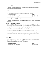
...support one device per connector. 1.6.3.1 Serial ATA Support The board's Serial ATA controller offers three independent Serial ATA ports with low-voltage power connectors. The port arrangement is the preferred mode for all ports. Native mode is as follows: • Four ports are implemented ...connectors • Four ports are assigned (IRQ 14 and 15). NOTE Many Serial ATA drives use new low-voltage power connectors and require adapters or power supplies equipped with a theoretical maximum transfer rate of the Serial ATA connectors Refer to two separate front panel USB headers For...
...support one device per connector. 1.6.3.1 Serial ATA Support The board's Serial ATA controller offers three independent Serial ATA ports with low-voltage power connectors. The port arrangement is the preferred mode for all ports. Native mode is as follows: • Four ports are implemented ...connectors • Four ports are assigned (IRQ 14 and 15). NOTE Many Serial ATA drives use new low-voltage power connectors and require adapters or power supplies equipped with a theoretical maximum transfer rate of the Serial ATA connectors Refer to two separate front panel USB headers For...

Product Specification
Page 22
...) might not be accurate. Intel Desktop Board DG41AN Technical Product Specification 1.7 Real-Time Clock Subsystem A coin-cell battery (CR2032) powers the real-time clock and CMOS memory. Figure 1 on . When the voltage drops below a certain level, the BIOS Setup program settings stored in , the standby current from the power supply extends the life of the...
...) might not be accurate. Intel Desktop Board DG41AN Technical Product Specification 1.7 Real-Time Clock Subsystem A coin-cell battery (CR2032) powers the real-time clock and CMOS memory. Figure 1 on . When the voltage drops below a certain level, the BIOS Setup program settings stored in , the standby current from the power supply extends the life of the...

Product Specification
Page 27
... (WfM) specification. The security feature uses a mechanical switch on the I /O Controller • Four thermal sensors (processor, 82G41 GMCH, 82801GB ICH7, and a remote thermal sensor) • Power supply monitoring of the fan headers Refer to Section 1.12.2.2, page 33 Figure 6, page 28 1.11.3 Chassis Intrusion and Detection The board supports a chassis security feature...
... (WfM) specification. The security feature uses a mechanical switch on the I /O Controller • Four thermal sensors (processor, 82G41 GMCH, 82801GB ICH7, and a remote thermal sensor) • Power supply monitoring of the fan headers Refer to Section 1.12.2.2, page 33 Figure 6, page 28 1.11.3 Chassis Intrusion and Detection The board supports a chassis security feature...

Product Specification
Page 30
... by the system chassis' power supply. 2. working D0 - Full power > 30 W G1 - Suspend to disk. Suspend to RAM. device specification specific. D3 - D3 - No power to put the system as a whole into a low-power state. Total system power is dependent on the system...C0 - Processor stopped C1 - S5 - Context not saved. Intel Desktop Board DG41AN Technical Product Specification 1.12.1.1 System States and Power States Under ACPI, the operating system directs all system and device power state transitions. The operating system uses information from the computer. ...
... by the system chassis' power supply. 2. working D0 - Full power > 30 W G1 - Suspend to disk. Suspend to RAM. device specification specific. D3 - D3 - No power to put the system as a whole into a low-power state. Total system power is dependent on the system...C0 - Processor stopped C1 - S5 - Context not saved. Intel Desktop Board DG41AN Technical Product Specification 1.12.1.1 System States and Power States Under ACPI, the operating system directs all system and device power state transitions. The operating system uses information from the computer. ...

Product Specification
Page 32
...features are used. NOTE The use of the main power connector Refer to Figure 10, page 42 Table 21, page 46 32 The computer's response can damage the power supply. Intel Desktop Board DG41AN Technical Product Specification 1.12.2 Hardware Support CAUTION Ensure that... provides full ACPI support. 1.12.2.1 Power Connector ATX12V-compliant power supplies can turn off ). When resuming from an AC power failure, the computer returns to ...
...features are used. NOTE The use of the main power connector Refer to Figure 10, page 42 Table 21, page 46 32 The computer's response can damage the power supply. Intel Desktop Board DG41AN Technical Product Specification 1.12.2 Hardware Support CAUTION Ensure that... provides full ACPI support. 1.12.2.1 Power Connector ATX12V-compliant power supplies can turn off ). When resuming from an AC power failure, the computer returns to ...

Product Specification
Page 33
...Table 16, page 44 Table 15, page 44 1.12.2.3 LAN Wake Capabilities CAUTION For LAN wake capabilities, the +5 V standby line from the power supply must be capable of providing adequate +5 V standby current. The front fan header has independent tachometer input to provide adequate standby current when implementing ...signal for PCI Express compliant LAN designs • The onboard LAN subsystem 33 All fan headers support closed-loop fan control that powers up of the computer through a network. Upon detecting a Magic Packet* frame, the LAN subsystem asserts a wake-up signal that can damage ...
...Table 16, page 44 Table 15, page 44 1.12.2.3 LAN Wake Capabilities CAUTION For LAN wake capabilities, the +5 V standby line from the power supply must be capable of providing adequate +5 V standby current. The front fan header has independent tachometer input to provide adequate standby current when implementing ...signal for PCI Express compliant LAN designs • The onboard LAN subsystem 33 All fan headers support closed-loop fan control that powers up of the computer through a network. Upon detecting a Magic Packet* frame, the LAN subsystem asserts a wake-up signal that can damage ...

Product Specification
Page 34
...wakes the computer from an ACPI S1 or S3 state. 34 Intel Desktop Board DG41AN Technical Product Specification 1.12.2.4 Instantly Available PC Technology CAUTION For Instantly Available PC technology, the +5 V standby line from the power supply must be capable of Instantly Available PC technology requires operating system ... an ACPI S1 or S3 state. Failure to provide adequate standby current when implementing Instantly Available PC technology can be off (the power supply is off if single colored.) When signaled by a wake-up device or event, the system quickly returns to enter the ACPI ...
...wakes the computer from an ACPI S1 or S3 state. 34 Intel Desktop Board DG41AN Technical Product Specification 1.12.2.4 Instantly Available PC Technology CAUTION For Instantly Available PC technology, the +5 V standby line from the power supply must be capable of Instantly Available PC technology requires operating system ... an ACPI S1 or S3 state. Failure to provide adequate standby current when implementing Instantly Available PC technology can be off (the power supply is off if single colored.) When signaled by a wake-up device or event, the system quickly returns to enter the ACPI ...

Product Specification
Page 46
... be unconnected. Failure to Section 2.5.1, page 53 46 a 2 x 12 connector. When using a 2 x 10 power supply cable, this pin will prevent the board from booting. Intel Desktop Board DG41AN Technical Product Specification 2.2.2.4 Power Supply Connectors The board has the following power supply connectors: • Main power - Main Power Connector Pin Signal Name Pin Signal Name 1 +3.3 V 13 +3.3 V 2 +3.3 V 14 -12 V 3 Ground 15 Ground...
... be unconnected. Failure to Section 2.5.1, page 53 46 a 2 x 12 connector. When using a 2 x 10 power supply cable, this pin will prevent the board from booting. Intel Desktop Board DG41AN Technical Product Specification 2.2.2.4 Power Supply Connectors The board has the following power supply connectors: • Main power - Main Power Connector Pin Signal Name Pin Signal Name 1 +3.3 V 13 +3.3 V 2 +3.3 V 14 -12 V 3 Ground 15 Ground...

Product Specification
Page 48
or two-color LED. The switch must pass before the power supply will recognize another on/off . (The time requirement is closed, the board resets and runs the POST. 2.2.2.5.3 Power/Sleep LED Header Pins 2 and 4 can be connected to a momentary single pole, single throw (SPST) ...seconds must pull the SW_ON# pin to ground for at least 50 ms to signal the power supply to a front panel momentary-contact power switch. States for a two-color LED. Table 25. Intel Desktop Board DG41AN Technical Product Specification 2.2.2.5.2 Reset Switch Header Pins 5 and 7 can be connected to a...
or two-color LED. The switch must pass before the power supply will recognize another on/off . (The time requirement is closed, the board resets and runs the POST. 2.2.2.5.3 Power/Sleep LED Header Pins 2 and 4 can be connected to a momentary single pole, single throw (SPST) ...seconds must pull the SW_ON# pin to ground for at least 50 ms to signal the power supply to a front panel momentary-contact power switch. States for a two-color LED. Table 25. Intel Desktop Board DG41AN Technical Product Specification 2.2.2.5.2 Reset Switch Header Pins 5 and 7 can be connected to a...

Product Specification
Page 53
...page 14 for a system consisting of a supported 65 W processor (see Section 1.3 on configurations chosen by the integrator. Table 27 lists the recommended power supply current values. Table 27. Recommended Power Supply Current Values Output Voltage 3.3 V 5 V 12 V1 12 V2 -12 V Current 14 A 12 A 10 A 10 A 0.3 A 5...), 1 GB DDR3 RAM, one hard disk drive, one optical drive, and all board peripherals enabled, the minimum recommended power supply is Plus 80 250 W. The total amount of standby current required depends on the wake devices supported and manufacturing options. Failure...
...page 14 for a system consisting of a supported 65 W processor (see Section 1.3 on configurations chosen by the integrator. Table 27 lists the recommended power supply current values. Table 27. Recommended Power Supply Current Values Output Voltage 3.3 V 5 V 12 V1 12 V2 -12 V Current 14 A 12 A 10 A 10 A 0.3 A 5...), 1 GB DDR3 RAM, one hard disk drive, one optical drive, and all board peripherals enabled, the minimum recommended power supply is Plus 80 250 W. The total amount of standby current required depends on the wake devices supported and manufacturing options. Failure...

Product Specification
Page 60
...Displays processor and memory configuration Configures advanced features available through the chipset Sets passwords and security features Power Boot Configures power management features and power supply controls Selects boot options Exit Saves or discards changes to configure the system. BIOS Setup Program Function...) Executes command or selects the submenu Load the default configuration values for use by the add-in card. 60 Intel Desktop Board DG41AN Technical Product Specification Table 31 lists the BIOS Setup program menu features. Table 32. PCI devices may be onboard...
...Displays processor and memory configuration Configures advanced features available through the chipset Sets passwords and security features Power Boot Configures power management features and power supply controls Selects boot options Exit Saves or discards changes to configure the system. BIOS Setup Program Function...) Executes command or selects the submenu Load the default configuration values for use by the add-in card. 60 Intel Desktop Board DG41AN Technical Product Specification Table 31 lists the BIOS Setup program menu features. Table 32. PCI devices may be onboard...

Product Specification
Page 82
... the following program requirements in the definition of new requirements. Intel Desktop Board DG41AN Technical Product Specification 5.1.5 ENERGY STAR* 5.0, e-Standby, and ErP Compliance The US Department of an efficient power supply: • Energy Star v5.0, category A • EPEAT* • Korea e-Standby • European Union Energy-related Products Directive 2009 (ErP) For information about ENERGY...
... the following program requirements in the definition of new requirements. Intel Desktop Board DG41AN Technical Product Specification 5.1.5 ENERGY STAR* 5.0, e-Standby, and ErP Compliance The US Department of an efficient power supply: • Energy Star v5.0, category A • EPEAT* • Korea e-Standby • European Union Energy-related Products Directive 2009 (ErP) For information about ENERGY...

Intel Desktop Board DG41AN Product Guide English
Page 5
Contents 1 Desktop Board Features Desktop Board Components 11 Processor ...12 Main Memory...13 Intel® G41 Express Chipset 15 Graphics Support 15 Intel® GMA X4500 Graphics Controller 15 DVI Support 15 Audio Subsystem 16 Legacy Input/Output (I/O) Controller 16 LAN...23 Battery ...23 Real-Time Clock 23 2 Installing and Replacing Desktop Board Components Before You Begin 24 Installation Precautions 25 Prevent Power Supply Overload 25 Observe Safety and Regulatory Requirements 25 Installing the I/O Shield 26 Installing and Removing the Desktop Board 27 Installing and Removing...
Contents 1 Desktop Board Features Desktop Board Components 11 Processor ...12 Main Memory...13 Intel® G41 Express Chipset 15 Graphics Support 15 Intel® GMA X4500 Graphics Controller 15 DVI Support 15 Audio Subsystem 16 Legacy Input/Output (I/O) Controller 16 LAN...23 Battery ...23 Real-Time Clock 23 2 Installing and Replacing Desktop Board Components Before You Begin 24 Installation Precautions 25 Prevent Power Supply Overload 25 Observe Safety and Regulatory Requirements 25 Installing the I/O Shield 26 Installing and Removing the Desktop Board 27 Installing and Removing...

Intel Desktop Board DG41AN Product Guide English
Page 6
Intel Desktop Board DG41AN Product Guide Connecting the Processor Fan Heat Sink Cable 32 Removing the Processor 32 Installing and Removing Memory 33 Installing DIMMs 34 Removing DIMMs 35 ... the Back Panel Audio Connectors 42 Connecting Chassis Fan and Power Supply Cables 43 Connecting a Chassis Fan Cable 43 Connecting Power Supply Cables 44 Setting the BIOS Configuration Jumper 45 Clearing Passwords 46 Replacing the Battery 47 3 Updating the BIOS Updating the BIOS with the Intel® Express BIOS Update Utility 52 Updating the BIOS...
Intel Desktop Board DG41AN Product Guide Connecting the Processor Fan Heat Sink Cable 32 Removing the Processor 32 Installing and Removing Memory 33 Installing DIMMs 34 Removing DIMMs 35 ... the Back Panel Audio Connectors 42 Connecting Chassis Fan and Power Supply Cables 43 Connecting a Chassis Fan Cable 43 Connecting Power Supply Cables 44 Setting the BIOS Configuration Jumper 45 Clearing Passwords 46 Replacing the Battery 47 3 Updating the BIOS Updating the BIOS with the Intel® Express BIOS Update Utility 52 Updating the BIOS...
Intel Desktop Board DG41AN Product Guide English
Page 7
...the Processor Fan Header ..........32 13. Internal Headers and Connectors 38 19. Connecting Power Supply Cables 44 22. Location of the Standby Power Indicator 22 4. Intel Desktop Board DG41AN China RoHS Material Self Declaration Table 63 Tables 1. Chassis Intrusion Header Signal Names... Example 33 14. Back Panel Audio Connectors 42 20. Feature Summary 9 2. Intel Desktop Board DG41AN Components 12 3. Alternate Front Panel Power LED Header Signal Names 41 12. Intel Desktop Board DG41AN Components 11 2. Installing the I/O Shield 26 5. Location of the Chassis Fan...
...the Processor Fan Header ..........32 13. Internal Headers and Connectors 38 19. Connecting Power Supply Cables 44 22. Location of the Standby Power Indicator 22 4. Intel Desktop Board DG41AN China RoHS Material Self Declaration Table 63 Tables 1. Chassis Intrusion Header Signal Names... Example 33 14. Back Panel Audio Connectors 42 20. Feature Summary 9 2. Intel Desktop Board DG41AN Components 12 3. Alternate Front Panel Power LED Header Signal Names 41 12. Intel Desktop Board DG41AN Components 11 2. Installing the I/O Shield 26 5. Location of the Chassis Fan...


