

Technical Product Specification
Page 8
Intel Desktop Board DCP847SKE Technical Product Specification 2 Technical Reference 2.1 Memory Resources 35 2.1.1 Addressable Memory 35 2.1.2 Memory Map 37 2.2 Connectors and Headers 37 2.2.1 Back Panel Connectors 38 2.2.2 Connectors and Headers (Bottom 39 2.3 BIOS Setup Configuration Jumper 46 2.4 Mechanical Considerations 48 2.4.1 Form Factor 48 2.5 Electrical Considerations 49 2.5.1 Power Supply...Security Feature 60 3.9 BIOS Security Features 61 4 Error Messages and Blink Codes 4.1 Front-panel Power LED Blink Codes 63 4.2 BIOS Error Messages 63 4.3 Port 80h POST Codes 64 5 ...
Intel Desktop Board DCP847SKE Technical Product Specification 2 Technical Reference 2.1 Memory Resources 35 2.1.1 Addressable Memory 35 2.1.2 Memory Map 37 2.2 Connectors and Headers 37 2.2.1 Back Panel Connectors 38 2.2.2 Connectors and Headers (Bottom 39 2.3 BIOS Setup Configuration Jumper 46 2.4 Mechanical Considerations 48 2.4.1 Form Factor 48 2.5 Electrical Considerations 49 2.5.1 Power Supply...Security Feature 60 3.9 BIOS Security Features 61 4 Error Messages and Blink Codes 4.1 Front-panel Power LED Blink Codes 63 4.2 BIOS Error Messages 63 4.3 Port 80h POST Codes 64 5 ...
Technical Product Specification
Page 9
... Memory Channel and SO-DIMM Configuration 21 5. Thermal Solution and Fan Header 29 7. Feature Summary 11 2. Effects of the Standby Power LED 34 8. BIOS Setup Configuration Jumper Settings 47 17. Boot Device Menu Options 59 ix Connection Diagram for a One-Color... 10 40 11. Dual-Port Front Panel USB 2.0 Header 42 13. 19 V Internal Power Supply Connector 43 14. LAN Connector LED Locations 27 6. LAN Connector LED States 27 6. Location of Pressing the Power Switch 30 7. Supported Memory Configurations 19 5. Location of the BIOS Configuration Setup Jumper 46 14...
... Memory Channel and SO-DIMM Configuration 21 5. Thermal Solution and Fan Header 29 7. Feature Summary 11 2. Effects of the Standby Power LED 34 8. BIOS Setup Configuration Jumper Settings 47 17. Boot Device Menu Options 59 ix Connection Diagram for a One-Color... 10 40 11. Dual-Port Front Panel USB 2.0 Header 42 13. 19 V Internal Power Supply Connector 43 14. LAN Connector LED Locations 27 6. LAN Connector LED States 27 6. Location of Pressing the Power Switch 30 7. Supported Memory Configurations 19 5. Location of the BIOS Configuration Setup Jumper 46 14...

Technical Product Specification
Page 12
Intel Desktop Board DCP847SKE Technical Product Specification Table 2. Feature Summary (continued) LAN Support Gigabit (10/100/1000 Mb/s) LAN subsystem using the Intel® 82579V Gigabit Ethernet Controller Hardware Monitor Subsystem Hardware monitoring subsystem, based on a Nuvoton NPCE791C embedded controller, including: • Voltage sense to detect out of range power supply voltages • Thermal sense to detect out of range thermal values • One processor fan header • Fan sense input used to monitor fan activity • Simple fan speed control 12
Intel Desktop Board DCP847SKE Technical Product Specification Table 2. Feature Summary (continued) LAN Support Gigabit (10/100/1000 Mb/s) LAN subsystem using the Intel® 82579V Gigabit Ethernet Controller Hardware Monitor Subsystem Hardware monitoring subsystem, based on a Nuvoton NPCE791C embedded controller, including: • Voltage sense to detect out of range power supply voltages • Thermal sense to detect out of range thermal values • One processor fan header • Fan sense input used to monitor fan activity • Simple fan speed control 12

Technical Product Specification
Page 18
... Unit of Computing Board Support Available configurations for providing power to Section 2.5.1 on page 49 for information on power supply requirements for this World Wide Web site: http://www.intel.com/products/motherboard/index.htm http://www.intel.com/p/en_US/support?iid=hdr+support http://ark.intel.com Chipset information BIOS and driver updates Tested memory...
... Unit of Computing Board Support Available configurations for providing power to Section 2.5.1 on page 49 for information on power supply requirements for this World Wide Web site: http://www.intel.com/products/motherboard/index.htm http://www.intel.com/p/en_US/support?iid=hdr+support http://ark.intel.com Chipset information BIOS and driver updates Tested memory...

Technical Product Specification
Page 25
... Figure 1 on page 13 shows the location of the battery. 1.9 LAN Subsystem The LAN subsystem consists of the following: • Intel 82579V Gigabit Ethernet Controller (10/100/1000 Mb/s) • Intel QS77 Express Chipset • RJ-45 LAN connector with integrated status LEDs Additional features of the LAN subsystem include: • CSMA... not be notified during the POST. When the voltage drops below a certain level, the BIOS Setup program settings stored in , the standby current from the power supply extends the life of three years. Replace the battery with 3.3 VSB applied via the...
... Figure 1 on page 13 shows the location of the battery. 1.9 LAN Subsystem The LAN subsystem consists of the following: • Intel 82579V Gigabit Ethernet Controller (10/100/1000 Mb/s) • Intel QS77 Express Chipset • RJ-45 LAN connector with integrated status LEDs Additional features of the LAN subsystem include: • CSMA... not be notified during the POST. When the voltage drops below a certain level, the BIOS Setup program settings stored in , the standby current from the power supply extends the life of three years. Replace the battery with 3.3 VSB applied via the...

Technical Product Specification
Page 31
.... Cold boot is disconnected from applications and user settings to put the system as a whole into a low-power state. C0 - no power except for wake-up devices used by the system chassis' power supply. 2. Full power > 30 W Power < 5 W (Note 2) Power < 5 W (Note 2) Power < 5 W (Note 2) G3 - Total system power is dependent on the system configuration, including add-in the system. 31
.... Cold boot is disconnected from applications and user settings to put the system as a whole into a low-power state. C0 - no power except for wake-up devices used by the system chassis' power supply. 2. Full power > 30 W Power < 5 W (Note 2) Power < 5 W (Note 2) Power < 5 W (Note 2) G3 - Total system power is dependent on the system configuration, including add-in the system. 31
Technical Product Specification
Page 33
.... 33 The LAN subsystem monitors network traffic at the Media Independent Interface. Table 9 on page 32 lists the devices and events that powers up of Instantly Available PC technology requires operating system support and drivers for any installed PCI Express add-in card. 1.11.2.3 LAN Wake...colored.) When signaled by a wake-up signal that can be off (the power supply is off ). Product Description 1.11.2.1 Power Input When resuming from an AC power failure, the computer returns to the power state it was in before power was interrupted (on or off , and the front panel LED is set...
.... 33 The LAN subsystem monitors network traffic at the Media Independent Interface. Table 9 on page 32 lists the devices and events that powers up of Instantly Available PC technology requires operating system support and drivers for any installed PCI Express add-in card. 1.11.2.3 LAN Wake...colored.) When signaled by a wake-up signal that can be off (the power supply is off ). Product Description 1.11.2.1 Power Input When resuming from an AC power failure, the computer returns to the power state it was in before power was interrupted (on or off , and the front panel LED is set...

Technical Product Specification
Page 43
...current rating is a connection diagram for the front panel header. Table 14. 19 V Internal Power Supply Connector Pin Signal Name 1 Ground 2 +19 V (±10%) For information about Power supply considerations Refer to +5V 3 HDD_LED# [Out] Hard disk activity LED 5 GROUND Ground 7... This section describes the functions of the front panel header. Table 15. Technical Reference 2.2.2.3 Power Supply Connectors The board has the following power supply connectors: • External Power Supply - Table 15 lists the signal names of the front panel header. Figure 11 is 10...
...current rating is a connection diagram for the front panel header. Table 14. 19 V Internal Power Supply Connector Pin Signal Name 1 Ground 2 +19 V (±10%) For information about Power supply considerations Refer to +5V 3 HDD_LED# [Out] Hard disk activity LED 5 GROUND Ground 7... This section describes the functions of the front panel header. Table 15. Technical Reference 2.2.2.3 Power Supply Connectors The board has the following power supply connectors: • External Power Supply - Table 15 lists the signal names of the front panel header. Figure 11 is 10...
Technical Product Specification
Page 45
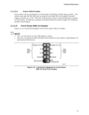
... on or off. (The time requirement is due to internal debounce circuitry on the board.) At least two seconds must pass before the power supply will recognize another on the USB header is a connection diagram for Front Panel USB 2.0 Dual-Port Header 45 Connection Diagram for the front... panel USB 2.0 header. NOTE • The +5 V DC power on /off signal. 2.2.2.5 Front Panel USB 2.0 Header Figure 12 is fused. • Use only a front panel USB connector that conforms to a front panel...
... on or off. (The time requirement is due to internal debounce circuitry on the board.) At least two seconds must pass before the power supply will recognize another on the USB header is a connection diagram for Front Panel USB 2.0 Dual-Port Header 45 Connection Diagram for the front... panel USB 2.0 header. NOTE • The +5 V DC power on /off signal. 2.2.2.5 Front Panel USB 2.0 Header Figure 12 is fused. • Use only a front panel USB connector that conforms to a front panel...

Technical Product Specification
Page 49
... no isolation circuitry between the external 19 V DC jack and the internal 1 x 2 power connector. Technical Reference 2.5 Electrical Considerations 2.5.1 Power Supply Considerations CAUTION The external 19 V DC jack is the primary power input connector of Intel Next Unit of both external and internal power supply units could result in the accessories box shall it be useful to be...
... no isolation circuitry between the external 19 V DC jack and the internal 1 x 2 power connector. Technical Reference 2.5 Electrical Considerations 2.5.1 Power Supply Considerations CAUTION The external 19 V DC jack is the primary power input connector of Intel Next Unit of both external and internal power supply units could result in the accessories box shall it be useful to be...

Technical Product Specification
Page 78
... governmental agencies in an adequate system configuration, including appropriate selection of Computing Board alone does not guarantee Energy Star compliance. Use of an Intel Next Unit of an efficient power supply: • Energy Star v5.2, category B • EPEAT* • Korea e-Standby • European Union Energy-related Products Directive 2013 (ErP) Lot 6 NOTE Energy...
... governmental agencies in an adequate system configuration, including appropriate selection of Computing Board alone does not guarantee Energy Star compliance. Use of an Intel Next Unit of an efficient power supply: • Energy Star v5.2, category B • EPEAT* • Korea e-Standby • European Union Energy-related Products Directive 2013 (ErP) Lot 6 NOTE Energy...


