

Technical Product Specification
Page 3
.... 2. Errata Current characterized errata, if any, are documented in Section 3.8 on page 60 regarding removing power before setting or clearing the hard disk drive password. The Intel® QS77 PCH and Intel® Celeron® processor 847 used on the component side of Changes or Clarifications January 2013 Spec Clarification Deleted the note in...
.... 2. Errata Current characterized errata, if any, are documented in Section 3.8 on page 60 regarding removing power before setting or clearing the hard disk drive password. The Intel® QS77 PCH and Intel® Celeron® processor 847 used on the component side of Changes or Clarifications January 2013 Spec Clarification Deleted the note in...

Technical Product Specification
Page 8
Intel Desktop Board DCP847SKE Technical Product Specification 2 Technical Reference 2.1 Memory Resources 35 2.1.1 Addressable Memory 35 2.1.2 Memory Map 37 2.2 Connectors and Headers 37 2.2.1 Back Panel Connectors 38 2.2.2 ... Screen 58 3.6 BIOS Recovery 58 3.7 Boot Options 59 3.7.1 Network Boot 59 3.7.2 Booting Without Attached Devices 59 3.7.3 Changing the Default Boot Device During POST 59 3.8 Hard Disk Drive Password Security Feature 60 3.9 BIOS Security Features 61 4 Error Messages and Blink Codes 4.1 Front-panel Power LED Blink Codes 63 4.2 BIOS Error Messages 63 4.3 Port...
Intel Desktop Board DCP847SKE Technical Product Specification 2 Technical Reference 2.1 Memory Resources 35 2.1.1 Addressable Memory 35 2.1.2 Memory Map 37 2.2 Connectors and Headers 37 2.2.1 Back Panel Connectors 38 2.2.2 ... Screen 58 3.6 BIOS Recovery 58 3.7 Boot Options 59 3.7.1 Network Boot 59 3.7.2 Booting Without Attached Devices 59 3.7.3 Changing the Default Boot Device During POST 59 3.8 Hard Disk Drive Password Security Feature 60 3.9 BIOS Security Features 61 4 Error Messages and Blink Codes 4.1 Front-panel Power LED Blink Codes 63 4.2 BIOS Error Messages 63 4.3 Port...

Technical Product Specification
Page 10
Port 80h POST Code Ranges 64 28. Regulatory Compliance Marks 79 x Safety Standards 71 31. Front-panel Power LED Blink Codes 63 26. EMC Regulations 75 32. Port 80h POST Codes 65 29. BIOS Error Messages 63 27. Intel Desktop Board DCP847SKE Technical Product Specification 23. Supervisor and User Password Functions 61 25. Typical Port 80h POST Sequence 69 30. Master Key and User Hard Drive Password Functions 60 24.
Port 80h POST Code Ranges 64 28. Regulatory Compliance Marks 79 x Safety Standards 71 31. Front-panel Power LED Blink Codes 63 26. EMC Regulations 75 32. Port 80h POST Codes 65 29. BIOS Error Messages 63 27. Intel Desktop Board DCP847SKE Technical Product Specification 23. Supervisor and User Password Functions 61 25. Typical Port 80h POST Sequence 69 30. Master Key and User Hard Drive Password Functions 60 24.

Technical Product Specification
Page 14
Intel Desktop Board DCP847SKE Technical Product Specification Table 3 lists the components identified in Figure 1 Item from Figure 1 A B Description Battery Standby power LED C Processor fan header D Onboard power button E Power LED F Hard Disk Drive LED G Thermal solution 14 Table 3. Components Shown in Figure 1.
Intel Desktop Board DCP847SKE Technical Product Specification Table 3 lists the components identified in Figure 1 Item from Figure 1 A B Description Battery Standby power LED C Processor fan header D Onboard power button E Power LED F Hard Disk Drive LED G Thermal solution 14 Table 3. Components Shown in Figure 1.
Technical Product Specification
Page 30
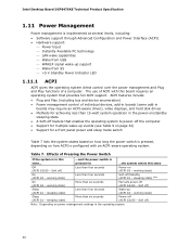
.../G5 - Table 7. Effects of individual devices, add-in boards (some add-in boards may require an ACPI-aware driver), video displays, and hard disk drives • Methods for a front panel power and sleep mode switch Table 7 lists the system states based on how long the power switch is... is in the power-on how ACPI is configured with this state Off (ACPI G2/G5 - working state) Sleep (ACPI G1 - Intel Desktop Board DCP847SKE Technical Product Specification 1.11 Power Management Power management is state... pressed for ...the system enters this board requires an operating ...
.../G5 - Table 7. Effects of individual devices, add-in boards (some add-in boards may require an ACPI-aware driver), video displays, and hard disk drives • Methods for a front panel power and sleep mode switch Table 7 lists the system states based on how long the power switch is... is in the power-on how ACPI is configured with this state Off (ACPI G2/G5 - working state) Sleep (ACPI G1 - Intel Desktop Board DCP847SKE Technical Product Specification 1.11 Power Management Power management is state... pressed for ...the system enters this board requires an operating ...

Technical Product Specification
Page 44
Proper LED function requires a SATA hard drive or optical drive connected to an onboard SATA connector. 2.2.2.4.2 Reset Switch Header Pins 5 and 7 can be connected to an LED to ...two-color LED. Table 16 shows the possible LED states. When the switch is normally open. Intel Desktop Board DCP847SKE Technical Product Specification Figure 11. States for Front Panel Header 2.2.2.4.1 Hard Drive Activity LED Header Pins 1 and 3 can be set via BIOS setup. 44 Table 16. ...Normal operation NOTE The LED behavior shown in Table 16 is being read from or written to a hard drive.
Proper LED function requires a SATA hard drive or optical drive connected to an onboard SATA connector. 2.2.2.4.2 Reset Switch Header Pins 5 and 7 can be connected to an LED to ...two-color LED. Table 16 shows the possible LED states. When the switch is normally open. Intel Desktop Board DCP847SKE Technical Product Specification Figure 11. States for Front Panel Header 2.2.2.4.1 Hard Drive Activity LED Header Pins 1 and 3 can be set via BIOS setup. 44 Table 16. ...Normal operation NOTE The LED behavior shown in Table 16 is being read from or written to a hard drive.

Technical Product Specification
Page 57
...instructions. 3.5 BIOS Updates The BIOS can be updated from a file on a hard disk, a USB drive (a flash drive or a USB hard drive), or a CD-ROM, or from the file location on the Intel World Wide Web site: • Intel® Express BIOS Update utility, which requires booting from the BIOS is set... devices are supported in the Windows environment. Check the Intel web site for support. 57 Using this utility, the BIOS can be updated from a file on a hard disk, a USB drive (a flash drive or a USB hard drive), or a CD-ROM. • Intel® F7 switch during POST allows a user to ...
...instructions. 3.5 BIOS Updates The BIOS can be updated from a file on a hard disk, a USB drive (a flash drive or a USB hard drive), or a CD-ROM, or from the file location on the Intel World Wide Web site: • Intel® Express BIOS Update utility, which requires booting from the BIOS is set... devices are supported in the Windows environment. Check the Intel web site for support. 57 Using this utility, the BIOS can be updated from a file on a hard disk, a USB drive (a flash drive or a USB hard drive), or a CD-ROM. • Intel® F7 switch during POST allows a user to ...

Technical Product Specification
Page 58
...custom splash screen. The Intel Integrator's Toolkit that is unlikely that can and cannot be made bootable. Table 22 lists the drives and media types that anything will share space with the Intel branded logo. Hard disk drive (connected to SATA or USB) Yes CD/DVD drive (connected to SATA or ...USB) Yes USB flash drive Yes USB diskette drive (with a custom splash screen. NOTE If...
...custom splash screen. The Intel Integrator's Toolkit that is unlikely that can and cannot be made bootable. Table 22 lists the drives and media types that anything will share space with the Intel branded logo. Hard disk drive (connected to SATA or USB) Yes CD/DVD drive (connected to SATA or ...USB) Yes USB flash drive Yes USB diskette drive (with a custom splash screen. NOTE If...

Technical Product Specification
Page 59
... embedded applications, the BIOS has been designed so that after passing the POST, the operating system loader is for the optical drive to be the first boot device, the hard drive second, removable drive third, and the network fourth. 3.7.1 Network Boot The network can choose to be selected as a boot device. Error Messages and... not present: • Video adapter • Keyboard • Mouse 3.7.3 Changing the Default Boot Device During POST Pressing the key during POST automatically forces booting from a hard drive, optical drive, removable drive, or the network.
... embedded applications, the BIOS has been designed so that after passing the POST, the operating system loader is for the optical drive to be the first boot device, the hard drive second, removable drive third, and the network fourth. 3.7.1 Network Boot The network can choose to be selected as a boot device. Error Messages and... not present: • Video adapter • Keyboard • Mouse 3.7.3 Changing the Default Boot Device During POST Pressing the key during POST automatically forces booting from a hard drive, optical drive, removable drive, or the network.

Technical Product Specification
Page 60
... Master Key or User hard disk drive password: Enter Hard Disk Drive Password: Upon successful entry of setting the Hard Disk Drive Passwords. Intel Desktop Board DCP847SKE Technical Product Specification 3.8 Hard Disk Drive Password Security Feature The Hard Disk Drive Password Security feature blocks read and write accesses to the hard disk drive until the Master Key or User hard disk drive password is submitted...
... Master Key or User hard disk drive password: Enter Hard Disk Drive Password: Upon successful entry of setting the Hard Disk Drive Passwords. Intel Desktop Board DCP847SKE Technical Product Specification 3.8 Hard Disk Drive Password Security Feature The Hard Disk Drive Password Security feature blocks read and write accesses to the hard disk drive until the Master Key or User hard disk drive password is submitted...

Technical Product Specification
Page 67
... mouse Detecting mouse Detecting presence of mouse Enabling mouse Fixed Media Resetting fixed media Disabling fixed media 0xB2 0xB3 Detecting presence of a fixed media (IDE hard drive detection etc.) Enabling/configuring a fixed media continued 67
... mouse Detecting mouse Detecting presence of mouse Enabling mouse Fixed Media Resetting fixed media Disabling fixed media 0xB2 0xB3 Detecting presence of a fixed media (IDE hard drive detection etc.) Enabling/configuring a fixed media continued 67


