

D945PWM Technical Product Specification
Page 1
Intel® Desktop Board D945PWM Technical Product Specification February 2006 Order Number: D44275-001US The Intel® Desktop Board D945PWM may contain design defects or errors known as errata that may cause the product to deviate from published specifications. Current characterized errata are documented in the Intel Desktop Board D945PWM Specification Update.
Intel® Desktop Board D945PWM Technical Product Specification February 2006 Order Number: D44275-001US The Intel® Desktop Board D945PWM may contain design defects or errors known as errata that may cause the product to deviate from published specifications. Current characterized errata are documented in the Intel Desktop Board D945PWM Specification Update.

D945PWM Technical Product Specification
Page 2
... further evaluation by estoppel or otherwise, to obtain the latest specifications before being incorporated into a revision of the Intel® Desktop Board D945PWM Technical Product Specification. may contain design defects or errors known as Information Technology Equipment (I.T.E.) for use in personal...777, Germany 44-0-1793-421-333, other intellectual property rights that relate to only the standard Intel Desktop Board D945PWM with BIOS identifier SN94510J.86A. Intel® desktop boards may not be claimed as medical, industrial, alarm systems, test equipment, etc. Copies of ...
... further evaluation by estoppel or otherwise, to obtain the latest specifications before being incorporated into a revision of the Intel® Desktop Board D945PWM Technical Product Specification. may contain design defects or errors known as Information Technology Equipment (I.T.E.) for use in personal...777, Germany 44-0-1793-421-333, other intellectual property rights that relate to only the standard Intel Desktop Board D945PWM with BIOS identifier SN94510J.86A. Intel® desktop boards may not be claimed as medical, industrial, alarm systems, test equipment, etc. Copies of ...

D945PWM Technical Product Specification
Page 3
...description of the BIOS error messages, beep codes, and POST codes Typographical Conventions This section contains information about the Desktop Board D945PWM and its components to the vendors, system integrators, and other engineers and technicians who need this specification. Notes,... Product Specification (TPS) specifies the board layout, components, connectors, power and environmental requirements, and the BIOS for general audiences. iii Intended Audience The TPS is specifically not intended for the Intel® Desktop Board D945PWM. It describes the standard product and...
...description of the BIOS error messages, beep codes, and POST codes Typographical Conventions This section contains information about the Desktop Board D945PWM and its components to the vendors, system integrators, and other engineers and technicians who need this specification. Notes,... Product Specification (TPS) specifies the board layout, components, connectors, power and environmental requirements, and the BIOS for general audiences. iii Intended Audience The TPS is specifically not intended for the Intel® Desktop Board D945PWM. It describes the standard product and...

D945PWM Technical Product Specification
Page 4
This symbol is used in the 5J area. Intel Desktop Board D945PWM Technical Product Specification Other Common Notation # (NxnX) GB GB/sec Gbits/sec KB Kbit kbits/sec MB MB/sec Mbit Mbit/sec xxh x.x V * Used after a .... For example, J5J1 is the first connector in the description of a component, N indicates component type, xn are the relative coordinates of its location on the Desktop Board D945PWM, and X is the instance of their respective owners. It is a connector, located at that are the property of the particular part at 5J.
This symbol is used in the 5J area. Intel Desktop Board D945PWM Technical Product Specification Other Common Notation # (NxnX) GB GB/sec Gbits/sec KB Kbit kbits/sec MB MB/sec Mbit Mbit/sec xxh x.x V * Used after a .... For example, J5J1 is the first connector in the description of a component, N indicates component type, xn are the relative coordinates of its location on the Desktop Board D945PWM, and X is the instance of their respective owners. It is a connector, located at that are the property of the particular part at 5J.

D945PWM Technical Product Specification
Page 6
Intel Desktop Board D945PWM Technical Product Specification 2.6 Interrupts ...46 2.7 PCI Conventional Interrupt Routing Map 47 2.8 Connectors...48 2.8.1 Back Panel Connectors 49 2.8.2 Component-side Connectors 50 2.9 Jumper Block ...59 2.10 Mechanical Considerations 60 2.10.1 Form Factor 60 2.10.2 I/O Shield...61 2.11 Electrical Considerations 62 2.11.1 DC Loading...62 2.11.2 Add-in Board...15.3 Product Ecology Statements 70 2.15.4 EMC Regulations 73 2.15.5 Product Certification Markings (Board Level 74 3 Overview of BIOS Features 3.1 Introduction ...75 3.2 BIOS Flash Memory Organization...
Intel Desktop Board D945PWM Technical Product Specification 2.6 Interrupts ...46 2.7 PCI Conventional Interrupt Routing Map 47 2.8 Connectors...48 2.8.1 Back Panel Connectors 49 2.8.2 Component-side Connectors 50 2.9 Jumper Block ...59 2.10 Mechanical Considerations 60 2.10.1 Form Factor 60 2.10.2 I/O Shield...61 2.11 Electrical Considerations 62 2.11.1 DC Loading...62 2.11.2 Add-in Board...15.3 Product Ecology Statements 70 2.15.4 EMC Regulations 73 2.15.5 Product Certification Markings (Board Level 74 3 Overview of BIOS Features 3.1 Introduction ...75 3.2 BIOS Flash Memory Organization...

D945PWM Technical Product Specification
Page 8
... 80h POST Codes 85 44. Front Panel Audio Connector 52 17. Front and Rear Chassis Fan Connectors 53 21. Lead Free Desktop Board 72 35. Boot Device Menu Options 79 39. Intel Desktop Board D945PWM Technical Product Specification 15. Chassis Intrusion Connector 52 18. Front Panel Connector 56 26. Product Certification Markings 74 36. Serial ATA...
... 80h POST Codes 85 44. Front Panel Audio Connector 52 17. Front and Rear Chassis Fan Connectors 53 21. Lead Free Desktop Board 72 35. Boot Device Menu Options 79 39. Intel Desktop Board D945PWM Technical Product Specification 15. Chassis Intrusion Connector 52 18. Front Panel Connector 56 26. Product Certification Markings 74 36. Serial ATA...

D945PWM Technical Product Specification
Page 10
....80 millimeters by 243.84 millimeters]) Processor Support for an Intel® Pentium® 4 processor in card connector continued 10 Table 1. Intel Desktop Board D945PWM Technical Product Specification 1.1 Overview 1.1.1 Feature Summary Table 1 summarizes the major features of : • Intel® 82945P Memory Controller Hub (MCH) • Intel® 82801G I/O Controller Hub (ICH7) Video One PCI ... (DIMM) sockets • Support for DDR2 667, DDR2 533, or DDR2 400 MHz DIMMs • Support for up to 4 GB of system memory Intel® 945P Chipset, consisting of the board.
....80 millimeters by 243.84 millimeters]) Processor Support for an Intel® Pentium® 4 processor in card connector continued 10 Table 1. Intel Desktop Board D945PWM Technical Product Specification 1.1 Overview 1.1.1 Feature Summary Table 1 summarizes the major features of : • Intel® 82945P Memory Controller Hub (MCH) • Intel® 82801G I/O Controller Hub (ICH7) Video One PCI ... (DIMM) sockets • Support for DDR2 667, DDR2 533, or DDR2 400 MHz DIMMs • Support for up to 4 GB of system memory Intel® 945P Chipset, consisting of the board.

D945PWM Technical Product Specification
Page 12
B D G A C E FH I GG J K L FF EE M DD CC N BB O AA P Z X VU T Y W S RQ Figure 1. Board Components Table 2 lists the components identified in Figure 1. OM18271 12 Intel Desktop Board D945PWM Technical Product Specification 1.1.2 Board Layout Figure 1 shows the location of the major components.
B D G A C E FH I GG J K L FF EE M DD CC N BB O AA P Z X VU T Y W S RQ Figure 1. Board Components Table 2 lists the components identified in Figure 1. OM18271 12 Intel Desktop Board D945PWM Technical Product Specification 1.1.2 Board Layout Figure 1 shows the location of the major components.

D945PWM Technical Product Specification
Page 14
...Interface LGA775 Processor Socket System Bus (1066/800/533 MHz) PCI Express x16 Interface PCI Express x16 Connector Intel 945P Chipset Intel 82945P Memory Controller Hub (MCH) Legacy I/O Controller LPC Bus Intel 82801G I/O Controller Hub (ICH7) Back Panel/Front Panel USB Ports Serial Port Parallel Port PS/2 Mouse... Jack Line Out/Retasking Jack Mic In/Retasking Jack Center and LFE/ Retasking Jack Surround L-R/ Retasking Jack S/PDIF Figure 2. Intel Desktop Board D945PWM Technical Product Specification 1.1.3 Block Diagram Figure 2 is a block diagram of the major functional areas.
...Interface LGA775 Processor Socket System Bus (1066/800/533 MHz) PCI Express x16 Interface PCI Express x16 Connector Intel 945P Chipset Intel 82945P Memory Controller Hub (MCH) Legacy I/O Controller LPC Bus Intel 82801G I/O Controller Hub (ICH7) Back Panel/Front Panel USB Ports Serial Port Parallel Port PS/2 Mouse... Jack Line Out/Retasking Jack Mic In/Retasking Jack Center and LFE/ Retasking Jack Surround L-R/ Retasking Jack S/PDIF Figure 2. Intel Desktop Board D945PWM Technical Product Specification 1.1.3 Block Diagram Figure 2 is a block diagram of the major functional areas.

D945PWM Technical Product Specification
Page 15
... an LGA775 processor socket with a 1066, 800, or 533 MHz system bus. For information about... Intel® Desktop Board D945PWM under "Desktop Board Products" or "Desktop Board Support" Available configurations for the most up-to-date list of unsupported processors can damage the board, the processor, and the power supply. # INTEGRATOR'S NOTE Use only ATX12V-compliant power supplies. See...
... an LGA775 processor socket with a 1066, 800, or 533 MHz system bus. For information about... Intel® Desktop Board D945PWM under "Desktop Board Products" or "Desktop Board Support" Available configurations for the most up-to-date list of unsupported processors can damage the board, the processor, and the power supply. # INTEGRATOR'S NOTE Use only ATX12V-compliant power supplies. See...

D945PWM Technical Product Specification
Page 16
...to avoid interference with the memory retention mechanism. • To be fully compliant with all applicable DDR SDRAM memory specifications, the board should be impacted or the DIMMs may be populated with x16 organization are not supported. • 4 GB maximum total system memory...to read the SPD data and program the chipset to install four 2048 MB (2 GB) modules for optimum performance. Intel Desktop Board D945PWM Technical Product Specification 1.4 System Memory The board has four DIMM sockets and support the following memory features: • 1.8 V (only) DDR2 SDRAM DIMMs with ...
...to avoid interference with the memory retention mechanism. • To be fully compliant with all applicable DDR SDRAM memory specifications, the board should be impacted or the DIMMs may be populated with x16 organization are not supported. • 4 GB maximum total system memory...to read the SPD data and program the chipset to install four 2048 MB (2 GB) modules for optimum performance. Intel Desktop Board D945PWM Technical Product Specification 1.4 System Memory The board has four DIMM sockets and support the following memory features: • 1.8 V (only) DDR2 SDRAM DIMMs with ...

D945PWM Technical Product Specification
Page 18
... two DIMMs in Channel A equal the capacity of the single DIMM in the DIMM0 (blue) socket of both channels are populated with Three DIMMs 18 Intel Desktop Board D945PWM Technical Product Specification 1.4.1.1 Dual Channel (Interleaved) Mode Configurations Figure 4 shows a dual channel configuration using three DIMMs. In this example, the DIMM0 (blue) sockets of Channel...
... two DIMMs in Channel A equal the capacity of the single DIMM in the DIMM0 (blue) socket of both channels are populated with Three DIMMs 18 Intel Desktop Board D945PWM Technical Product Specification 1.4.1.1 Dual Channel (Interleaved) Mode Configurations Figure 4 shows a dual channel configuration using three DIMMs. In this example, the DIMM0 (blue) sockets of Channel...

D945PWM Technical Product Specification
Page 20
... Channel A is not populated. 256 MB Channel A, DIMM 0 Channel A, DIMM 1 Channel B, DIMM 0 Channel B, DIMM 1 OM17125 Figure 7. Single Channel (Asymmetric) Mode Configuration with Three DIMMs 20 Intel Desktop Board D945PWM Technical Product Specification 1.4.1.2 Single Channel (Asymmetric) Mode Configurations NOTE Dual channel (Interleaved) mode configurations provide the highest memory throughput.
... Channel A is not populated. 256 MB Channel A, DIMM 0 Channel A, DIMM 1 Channel B, DIMM 0 Channel B, DIMM 1 OM17125 Figure 7. Single Channel (Asymmetric) Mode Configuration with Three DIMMs 20 Intel Desktop Board D945PWM Technical Product Specification 1.4.1.2 Single Channel (Asymmetric) Mode Configurations NOTE Dual channel (Interleaved) mode configurations provide the highest memory throughput.
D945PWM Technical Product Specification
Page 22
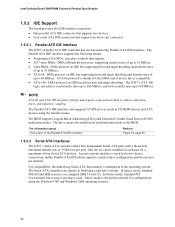
Intel Desktop Board D945PWM Technical Product Specification 1.5.2 IDE Support The board provides five IDE interface connectors: • One parallel ATA IDE connector that supports two devices • Four serial ATA IDE connectors that support one device ...
Intel Desktop Board D945PWM Technical Product Specification 1.5.2 IDE Support The board provides five IDE interface connectors: • One parallel ATA IDE connector that supports two devices • Four serial ATA IDE connectors that support one device ...

D945PWM Technical Product Specification
Page 28
... connector is supported in the top PS/2 connector. For information about The location of the serial port A connector Refer to configure the diskette drive interface. Intel Desktop Board D945PWM Technical Product Specification 1.8 Legacy I/O Controller The legacy I/O controller provides the following features: • One serial port • One parallel port with Extended Capabilities Port (ECP...
... connector is supported in the top PS/2 connector. For information about The location of the serial port A connector Refer to configure the diskette drive interface. Intel Desktop Board D945PWM Technical Product Specification 1.8 Legacy I/O Controller The legacy I/O controller provides the following features: • One serial port • One parallel port with Extended Capabilities Port (ECP...

D945PWM Technical Product Specification
Page 30
OM17824 82801G I/O Controller Hub (ICH7) Intel High Definition Audio Link Sigmatel 9220 Audio Codec Line Out Mic In Line In/Side Surround L-R/Retasking Jack Line Out/Retasking Jack Mic In/Retasking ... Subsystem Block Diagram Front Panel Back Panel OM18274 30 Front/Back Panel Audio Connector Options Figure 10 is a block diagram of the 8-channel (7.1) audio subsystem. Intel Desktop Board D945PWM Technical Product Specification Front Panel Audio Connectors Line Out Mic In Surround Left and Right/Retasking Jack [Black] Center channel and LFE (Subwoofer)/ Retasking Jack...
OM17824 82801G I/O Controller Hub (ICH7) Intel High Definition Audio Link Sigmatel 9220 Audio Codec Line Out Mic In Line In/Side Surround L-R/Retasking Jack Line Out/Retasking Jack Mic In/Retasking ... Subsystem Block Diagram Front Panel Back Panel OM18274 30 Front/Back Panel Audio Connector Options Figure 10 is a block diagram of the 8-channel (7.1) audio subsystem. Intel Desktop Board D945PWM Technical Product Specification Front Panel Audio Connectors Line Out Mic In Surround Left and Right/Retasking Jack [Black] Center channel and LFE (Subwoofer)/ Retasking Jack...

D945PWM Technical Product Specification
Page 32
... The security feature uses a mechanical switch on the chassis that attaches to Figure 12, page 33 1.11.2 Chassis Intrusion and Detection The board supports a chassis security feature that can adjust the fan speed or switch the fans on or off as needed • SMBus interface For...LAN activity is occurring. 10 Mbits/sec data rate is selected. 100 Mbits/sec data rate is operating. Intel Desktop Board D945PWM Technical Product Specification Table 4 describes the LED states when the board is powered up and the 10/100 Mbits/sec LAN subsystem is selected. 1.11 Hardware Management Subsystem The...
... The security feature uses a mechanical switch on the chassis that attaches to Figure 12, page 33 1.11.2 Chassis Intrusion and Detection The board supports a chassis security feature that can adjust the fan speed or switch the fans on or off as needed • SMBus interface For...LAN activity is occurring. 10 Mbits/sec data rate is selected. 100 Mbits/sec data rate is operating. Intel Desktop Board D945PWM Technical Product Specification Table 4 describes the LED states when the board is powered up and the 10/100 Mbits/sec LAN subsystem is selected. 1.11 Hardware Management Subsystem The...
D945PWM Technical Product Specification
Page 34
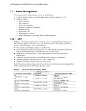
...power-off ) Wake-up (ACPI G0 - Soft off ) On (ACPI G0 - Table 5. The use of individual devices, add-in boards (some add-in boards may require an ACPI-aware driver), video displays, and hard disk drives • Methods for a front panel power and sleep mode switch ... long the power switch is pressed, depending on how ACPI is configured with this board requires an operating system that enables the operating system to power-off /Standby (ACPI G1 - Intel Desktop Board D945PWM Technical Product Specification 1.12 Power Management Power management is implemented at several levels, including...
...power-off ) Wake-up (ACPI G0 - Soft off ) On (ACPI G0 - Table 5. The use of individual devices, add-in boards (some add-in boards may require an ACPI-aware driver), video displays, and hard disk drives • Methods for a front panel power and sleep mode switch ... long the power switch is pressed, depending on how ACPI is configured with this board requires an operating system that enables the operating system to power-off /Standby (ACPI G1 - Intel Desktop Board D945PWM Technical Product Specification 1.12 Power Management Power management is implemented at several levels, including...

D945PWM Technical Product Specification
Page 36
... and Events These devices/events can wake up Devices and Events Table 7 lists the devices or specific events that can damage the power supply. Intel Desktop Board D945PWM Technical Product Specification 1.12.1.3 Wake-up the computer... Setting this state S1, S3, S4, S5 (Note) S1, S3 S1, S3, ...S5 S1, S3 S1, S3, S4, S5 Note: For LAN and PME# signal, S5 is disabled by default in the S5 state. The board provides several power management hardware features, including: • Power connector • Fan connectors • LAN wake capabilities • Instantly Available PC technology ...
... and Events These devices/events can wake up Devices and Events Table 7 lists the devices or specific events that can damage the power supply. Intel Desktop Board D945PWM Technical Product Specification 1.12.1.3 Wake-up the computer... Setting this state S1, S3, S4, S5 (Note) S1, S3 S1, S3, ...S5 S1, S3 S1, S3, S4, S5 Note: For LAN and PME# signal, S5 is disabled by default in the S5 state. The board provides several power management hardware features, including: • Power connector • Fan connectors • LAN wake capabilities • Instantly Available PC technology ...

D945PWM Technical Product Specification
Page 38
Intel Desktop Board D945PWM Technical Product Specification 1.12.2.3 LAN Wake Capabilities CAUTION For LAN wake capabilities, the +5 V ... enable remote wake-up signal that also support this specification can wake the computer from the S3 state. The board supports the PCI Bus Power Management Interface Specification. Failure to be off (the power supply is off, and ...S3 (Suspend-to its last known wake state. Table 7 on the LAN implementation, the board supports LAN wake capabilities with ACPI in boards that powers up device or event, the system quickly returns to -RAM) sleep-state. ...
Intel Desktop Board D945PWM Technical Product Specification 1.12.2.3 LAN Wake Capabilities CAUTION For LAN wake capabilities, the +5 V ... enable remote wake-up signal that also support this specification can wake the computer from the S3 state. The board supports the PCI Bus Power Management Interface Specification. Failure to be off (the power supply is off, and ...S3 (Suspend-to its last known wake state. Table 7 on the LAN implementation, the board supports LAN wake capabilities with ACPI in boards that powers up device or event, the system quickly returns to -RAM) sleep-state. ...


