
NVIDIA* GeForce* 6200 LE Graphics Card Product Specification
Page 1
LR Code: LR2A1N Product Features: GeForce 6200LE(NV44V) PCI Express 16x 16MB 32Bit, supporting 128MB DVI-D/TVOUT/VGA Product Approval Sheet e Revision History : Revision 03 Description Revised to add the newly-approved memory. 02 Revised the memory clock to 275MHz 01 First Release for evaluation Doc No. S2A1N-Intel-03 Date:Jan 24, 2006 Release Date Jan 24, 2006 Jan , 2006 Dec 13. 2005 Approval : Prepared By: Axel Lee Reviewed By: Approved By: Date: Jan 24, 2006 Date: Date: 1
LR Code: LR2A1N Product Features: GeForce 6200LE(NV44V) PCI Express 16x 16MB 32Bit, supporting 128MB DVI-D/TVOUT/VGA Product Approval Sheet e Revision History : Revision 03 Description Revised to add the newly-approved memory. 02 Revised the memory clock to 275MHz 01 First Release for evaluation Doc No. S2A1N-Intel-03 Date:Jan 24, 2006 Release Date Jan 24, 2006 Jan , 2006 Dec 13. 2005 Approval : Prepared By: Axel Lee Reviewed By: Approved By: Date: Jan 24, 2006 Date: Date: 1

NVIDIA* GeForce* 6200 LE Graphics Card Product Specification
Page 2
... the maximum performance • Installation software requires CD-ROM drive 1.2 Graphics Technology Nvidia GeForce 6200LE GPU 1.3 Memory Configuration • 16MB/32Bit of DDR memory on board, able to support 128MB memory 1.4 Operating System Support • Windows® XP • Windows® 2000 1.5 Display Support DAC maximum resolution/refresh: 2048 × 1536 × 32...
... the maximum performance • Installation software requires CD-ROM drive 1.2 Graphics Technology Nvidia GeForce 6200LE GPU 1.3 Memory Configuration • 16MB/32Bit of DDR memory on board, able to support 128MB memory 1.4 Operating System Support • Windows® XP • Windows® 2000 1.5 Display Support DAC maximum resolution/refresh: 2048 × 1536 × 32...

NVIDIA* GeForce* 6200 LE Graphics Card Product Specification
Page 3
ATX Bracket o PCB - Low Profile • Number of Pipeline: 4 2.2 Memory Type: 16MB TSOP DDR Memory, 4Mx32 (- 28)x1pcs, memory bandwidth: 32bit • Memory Clock: 275MHz • Memory Adopted: Vendor Part Number Specification Hynix HY5DU283222BFP-28 FBGA144/4Mx32 Hynix HY5DU283222AFP-28 FBGA144/4Mx32 2.3 PCBA- • Form factor o Bracket - 2. Product Details 2.1 Graphics Core(GPU) ...
ATX Bracket o PCB - Low Profile • Number of Pipeline: 4 2.2 Memory Type: 16MB TSOP DDR Memory, 4Mx32 (- 28)x1pcs, memory bandwidth: 32bit • Memory Clock: 275MHz • Memory Adopted: Vendor Part Number Specification Hynix HY5DU283222BFP-28 FBGA144/4Mx32 Hynix HY5DU283222AFP-28 FBGA144/4Mx32 2.3 PCBA- • Form factor o Bracket - 2. Product Details 2.1 Graphics Core(GPU) ...

D945PWM Technical Product Specification
Page 5
...Overview ...10 1.1.1 Feature Summary 10 1.1.2 Board Layout 12 1.1.3 Block Diagram 14 1.2 Online Support ...15 1.3 Processor ...15 1.4 System Memory ...16 1.4.1 Memory Configurations 17 1.5 Intel® 945P Chipset...21 1.5.1 USB ...21 1.5.2 IDE Support 22 1.5.3 Real-Time Clock, CMOS SRAM, and Battery 23 1.6 PCI...1.9.2 Audio Connectors 29 1.9.3 8-Channel (7.1) Audio Subsystem 29 1.10 LAN Subsystem ...31 1.10.1 LAN Subsystem Software 31 1.10.2 Intel® 82562GX Physical Layer Interface Device 31 1.10.3 RJ-45 LAN Connector with Integrated LEDs 31 1.11 Hardware Management Subsystem 32 ...
...Overview ...10 1.1.1 Feature Summary 10 1.1.2 Board Layout 12 1.1.3 Block Diagram 14 1.2 Online Support ...15 1.3 Processor ...15 1.4 System Memory ...16 1.4.1 Memory Configurations 17 1.5 Intel® 945P Chipset...21 1.5.1 USB ...21 1.5.2 IDE Support 22 1.5.3 Real-Time Clock, CMOS SRAM, and Battery 23 1.6 PCI...1.9.2 Audio Connectors 29 1.9.3 8-Channel (7.1) Audio Subsystem 29 1.10 LAN Subsystem ...31 1.10.1 LAN Subsystem Software 31 1.10.2 Intel® 82562GX Physical Layer Interface Device 31 1.10.3 RJ-45 LAN Connector with Integrated LEDs 31 1.11 Hardware Management Subsystem 32 ...

D945PWM Technical Product Specification
Page 6
Intel Desktop Board D945PWM Technical Product Specification 2.6 Interrupts ...46 2.7 PCI Conventional Interrupt Routing Map 47 2.8 Connectors...48 2.8.1 Back Panel Connectors 49 2.8.2 Component-side Connectors 50 2.9 ....3 Product Ecology Statements 70 2.15.4 EMC Regulations 73 2.15.5 Product Certification Markings (Board Level 74 3 Overview of BIOS Features 3.1 Introduction ...75 3.2 BIOS Flash Memory Organization 76 3.3 Resource Configuration 76 3.3.1 PCI Autoconfiguration 76 3.3.2 PCI IDE Support 76 3.4 System Management BIOS (SMBIOS 77 3.5 Legacy USB Support...77 3.6 BIOS Updates ...
Intel Desktop Board D945PWM Technical Product Specification 2.6 Interrupts ...46 2.7 PCI Conventional Interrupt Routing Map 47 2.8 Connectors...48 2.8.1 Back Panel Connectors 49 2.8.2 Component-side Connectors 50 2.9 ....3 Product Ecology Statements 70 2.15.4 EMC Regulations 73 2.15.5 Product Certification Markings (Board Level 74 3 Overview of BIOS Features 3.1 Introduction ...75 3.2 BIOS Flash Memory Organization 76 3.3 Resource Configuration 76 3.3.1 PCI Autoconfiguration 76 3.3.2 PCI IDE Support 76 3.4 System Management BIOS (SMBIOS 77 3.5 Legacy USB Support...77 3.6 BIOS Updates ...

D945PWM Technical Product Specification
Page 7
...19. Board Dimensions...60 22. I /O Map ...44 11. Processor Heatsink for Front Panel Connector 56 18. DMA Channels ...43 10. System Memory Map 43 9. Contents 4 Error Messages and Beep Codes 4.1 Speaker ...83 4.2 BIOS Beep Codes...83 4.3 BIOS Error Messages 83 4.4 Port 80h...30 10. 8-channel (7.1) Audio Subsystem Block Diagram 30 11. LAN Connector LED Locations 31 12. I /O Shield Dimensions 61 23. Memory Channel and DIMM Configuration 17 4. Connection Diagram for Omni-directional Airflow 64 24. Localized High Temperature Zones 65 Tables 1. Wake-up Devices...
...19. Board Dimensions...60 22. I /O Map ...44 11. Processor Heatsink for Front Panel Connector 56 18. DMA Channels ...43 10. System Memory Map 43 9. Contents 4 Error Messages and Beep Codes 4.1 Speaker ...83 4.2 BIOS Beep Codes...83 4.3 BIOS Error Messages 83 4.4 Port 80h...30 10. 8-channel (7.1) Audio Subsystem Block Diagram 30 11. LAN Connector LED Locations 31 12. I /O Shield Dimensions 61 23. Memory Channel and DIMM Configuration 17 4. Connection Diagram for Omni-directional Airflow 64 24. Localized High Temperature Zones 65 Tables 1. Wake-up Devices...

D945PWM Technical Product Specification
Page 9
1 Product Description What This Chapter Contains 1.1 Overview ...10 1.2 Online Support ...15 1.3 Processor ...15 1.4 System Memory ...16 1.5 Intel® 945P Chipset...21 1.6 PCI Express Connectors 27 1.7 IEEE-1394a Connectors 27 1.8 Legacy I/O Controller 28 1.9 Audio Subsystem ...29 1.10 LAN Subsystem ...31 1.11 Hardware Management Subsystem 32 1.12 Power Management ...34 9
1 Product Description What This Chapter Contains 1.1 Overview ...10 1.2 Online Support ...15 1.3 Processor ...15 1.4 System Memory ...16 1.5 Intel® 945P Chipset...21 1.6 PCI Express Connectors 27 1.7 IEEE-1394a Connectors 27 1.8 Legacy I/O Controller 28 1.9 Audio Subsystem ...29 1.10 LAN Subsystem ...31 1.11 Hardware Management Subsystem 32 1.12 Power Management ...34 9

D945PWM Technical Product Specification
Page 10
... SPI Flash device) • Support for up to 4 GB of system memory Intel® 945P Chipset, consisting of the board. Intel Desktop Board D945PWM Technical Product Specification 1.1 Overview 1.1.1 Feature Summary Table 1 summarizes the major features of : • Intel® 82945P Memory Controller Hub (MCH) • Intel® 82801G I/O Controller Hub (ICH7) Video One PCI Express* x16 bus...
... SPI Flash device) • Support for up to 4 GB of system memory Intel® 945P Chipset, consisting of the board. Intel Desktop Board D945PWM Technical Product Specification 1.1 Overview 1.1.1 Feature Summary Table 1 summarizes the major features of : • Intel® 82945P Memory Controller Hub (MCH) • Intel® 82801G I/O Controller Hub (ICH7) Video One PCI Express* x16 bus...

D945PWM Technical Product Specification
Page 14
Intel Desktop Board D945PWM Technical Product Specification 1.1.3 Block Diagram Figure 2 is a block diagram of the major functional areas. PCI Express x1 Interface PCI Express x1 Slot 1 PCI Express x1 ... ATA IDE Interface LGA775 Processor Socket System Bus (1066/800/533 MHz) PCI Express x16 Interface PCI Express x16 Connector Intel 945P Chipset Intel 82945P Memory Controller Hub (MCH) Legacy I/O Controller LPC Bus Intel 82801G I/O Controller Hub (ICH7) Back Panel/Front Panel USB Ports Serial Port Parallel Port PS/2 Mouse PS/2 Keyboard Diskette Drive...
Intel Desktop Board D945PWM Technical Product Specification 1.1.3 Block Diagram Figure 2 is a block diagram of the major functional areas. PCI Express x1 Interface PCI Express x1 Slot 1 PCI Express x1 ... ATA IDE Interface LGA775 Processor Socket System Bus (1066/800/533 MHz) PCI Express x16 Interface PCI Express x16 Connector Intel 945P Chipset Intel 82945P Memory Controller Hub (MCH) Legacy I/O Controller LPC Bus Intel 82801G I/O Controller Hub (ICH7) Back Panel/Front Panel USB Ports Serial Port Parallel Port PS/2 Mouse PS/2 Keyboard Diskette Drive...

D945PWM Technical Product Specification
Page 16
... (2 GB) modules for information on page 41 for a total of 8 GB of system memory, however, only 4 GB of address space is available. Intel Desktop Board D945PWM Technical Product Specification 1.4 System Memory The board has four DIMM sockets and support the following memory features: • 1.8 V (only) DDR2 SDRAM DIMMs with gold-plated contacts • Unbuffered, single...
... (2 GB) modules for information on page 41 for a total of 8 GB of system memory, however, only 4 GB of address space is available. Intel Desktop Board D945PWM Technical Product Specification 1.4 System Memory The board has four DIMM sockets and support the following memory features: • 1.8 V (only) DDR2 SDRAM DIMMs with gold-plated contacts • Unbuffered, single...

D945PWM Technical Product Specification
Page 17
... 1.4.1 Memory Configurations The Intel 82945P MCH supports two types of both channels are used between channels, the slowest memory timing will be equal. This mode is enabled when the installed memory capacities of both DIMM channels are black. Memory Channel and...mode is used . • Single channel (Asymmetric) mode. If different speed DIMMs are blue. Figure 3 illustrates the memory channel and DIMM configuration. NOTE The DIMM0 sockets of memory organization: • Dual channel (Interleaved) mode. Channel A, DIMM 0 Channel A, DIMM 1 Channel B, DIMM 0 Channel...
... 1.4.1 Memory Configurations The Intel 82945P MCH supports two types of both channels are used between channels, the slowest memory timing will be equal. This mode is enabled when the installed memory capacities of both DIMM channels are black. Memory Channel and...mode is used . • Single channel (Asymmetric) mode. If different speed DIMMs are blue. Figure 3 illustrates the memory channel and DIMM configuration. NOTE The DIMM0 sockets of memory organization: • Dual channel (Interleaved) mode. Channel A, DIMM 0 Channel A, DIMM 1 Channel B, DIMM 0 Channel...

D945PWM Technical Product Specification
Page 20
... A is not populated. 256 MB Channel A, DIMM 0 Channel A, DIMM 1 Channel B, DIMM 0 Channel B, DIMM 1 OM17125 Figure 7. Intel Desktop Board D945PWM Technical Product Specification 1.4.1.2 Single Channel (Asymmetric) Mode Configurations NOTE Dual channel (Interleaved) mode configurations provide the highest memory throughput. Figure 7 shows a single channel configuration using three DIMMs. In this example, only the DIMM0 (blue...
... A is not populated. 256 MB Channel A, DIMM 0 Channel A, DIMM 1 Channel B, DIMM 0 Channel B, DIMM 1 OM17125 Figure 7. Intel Desktop Board D945PWM Technical Product Specification 1.4.1.2 Single Channel (Asymmetric) Mode Configurations NOTE Dual channel (Interleaved) mode configurations provide the highest memory throughput. Figure 7 shows a single channel configuration using three DIMMs. In this example, only the DIMM0 (blue...
D945PWM Technical Product Specification
Page 21
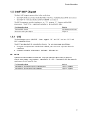
...; Four ports are implemented with DMI interconnect The MCH component provides interfaces to the CPU, memory, PCI Express, and the DMI interconnect. For information about The Intel 945P chipset Resources used by the chipset Refer to http://developer.intel.com/ Chapter 2 1.5.1 USB The board supports up to the cable. The ICH7 provides the... UHCI- and EHCI-compatible drivers. For information about The location of the USB connectors on the back panel The location of the following devices: • Intel 82945P Memory Controller Hub (MCH) with Direct Media Interface (DMI) interconnect •...
...; Four ports are implemented with DMI interconnect The MCH component provides interfaces to the CPU, memory, PCI Express, and the DMI interconnect. For information about The Intel 945P chipset Resources used by the chipset Refer to http://developer.intel.com/ Chapter 2 1.5.1 USB The board supports up to the cable. The ICH7 provides the... UHCI- and EHCI-compatible drivers. For information about The location of the USB connectors on the back panel The location of the following devices: • Intel 82945P Memory Controller Hub (MCH) with Direct Media Interface (DMI) interconnect •...

D945PWM Technical Product Specification
Page 23
... connectors Refer to Figure 16, page 50 1.5.3 Real-Time Clock, CMOS SRAM, and Battery A coin-cell battery (CR2032) powers the real-time clock and CMOS memory. Disposal of three years. Batterier bør om muligt genbruges. Bortskaffelse af brugte batterier bør foregå i overensstemmelse med gældende miljølovgivning. Brukte batterier...
... connectors Refer to Figure 16, page 50 1.5.3 Real-Time Clock, CMOS SRAM, and Battery A coin-cell battery (CR2032) powers the real-time clock and CMOS memory. Disposal of three years. Batterier bør om muligt genbruges. Bortskaffelse af brugte batterier bør foregå i overensstemmelse med gældende miljølovgivning. Brukte batterier...

D945PWM Technical Product Specification
Page 41
... found with their respective section headings. 2.2 Memory Resources 2.2.1 Addressable Memory The board utilizes 4 GB of system memory installed, it is allocated for other system critical functions. 2 Technical Reference What This Chapter Contains 2.1 Introduction ...41 2.2 Memory Resources ...41 2.3 DMA Channels ...43 2.4.../O map, Table 11 defines the PCI Conventional bus configuration space map, and Table 12 describes the interrupts. Table 8 describes the system memory map, Table 9 lists the DMA channels, Table 10 shows the I /O Map...44 2.5 PCI Configuration Space Map 45 2.6 Interrupts ...
... found with their respective section headings. 2.2 Memory Resources 2.2.1 Addressable Memory The board utilizes 4 GB of system memory installed, it is allocated for other system critical functions. 2 Technical Reference What This Chapter Contains 2.1 Introduction ...41 2.2 Memory Resources ...41 2.3 DMA Channels ...43 2.4.../O map, Table 11 defines the PCI Conventional bus configuration space map, and Table 12 describes the interrupts. Table 8 describes the system memory map, Table 9 lists the DMA channels, Table 10 shows the I /O Map...44 2.5 PCI Configuration Space Map 45 2.6 Interrupts ...

D945PWM Technical Product Specification
Page 42
... Buffer area (128 KB; 16 KB x 8) Standard PCI/ ISA Video Memory (SMM Memory) 128 KB DOS area (640 KB) 1 MB 960 KB 896 KB 768 KB 640 KB 0 KB OM17140 Figure 14. Intel Desktop Board D945PWM Technical Product Specification • MCH base address registers, internal graphics ranges, PCI... Express ports (up to 512 MB) • Memory-mapped I/O that can be used when there is dynamically allocated for PCI Conventional...
... Buffer area (128 KB; 16 KB x 8) Standard PCI/ ISA Video Memory (SMM Memory) 128 KB DOS area (640 KB) 1 MB 960 KB 896 KB 768 KB 640 KB 0 KB OM17140 Figure 14. Intel Desktop Board D945PWM Technical Product Specification • MCH base address registers, internal graphics ranges, PCI... Express ports (up to 512 MB) • Memory-mapped I/O that can be used when there is dynamically allocated for PCI Conventional...

D945PWM Technical Product Specification
Page 43
... 160 KB 1 KB 127 KB 512 KB Description Extended memory Runtime BIOS Reserved Potential available high DOS memory (open to the PCI Conventional bus). Dependent on video adapter used. Technical Reference 2.2.2 Memory Map Table 8 lists the system memory map. FFFFF E0000 - System Memory Map Address Range (decimal) 1024 K - 4194304 K ...DMA controller Open Open Open 43 DFFFF 640 K - 800 K 639 K - 640 K 512 K - 639 K 0 K - 512 K A0000 - Video memory and BIOS Extended BIOS data (movable by memory manager software) Extended conventional memory Conventional memory 2.3 DMA Channels Table 9.
... 160 KB 1 KB 127 KB 512 KB Description Extended memory Runtime BIOS Reserved Potential available high DOS memory (open to the PCI Conventional bus). Dependent on video adapter used. Technical Reference 2.2.2 Memory Map Table 8 lists the system memory map. FFFFF E0000 - System Memory Map Address Range (decimal) 1024 K - 4194304 K ...DMA controller Open Open Open 43 DFFFF 640 K - 800 K 639 K - 640 K 512 K - 639 K 0 K - 512 K A0000 - Video memory and BIOS Extended BIOS data (movable by memory manager software) Extended conventional memory Conventional memory 2.3 DMA Channels Table 9.

D945PWM Technical Product Specification
Page 45
...02 03 00 01 02 03 07 00 00 01 02 03 00 00 00 00 00 00 00 Description Memory controller of Intel 82945P component PCI Express x16 graphics port (Note 1) Intel High Definition Audio Controller PCI Express port 1 PCI Express port 2 PCI Express port 3 PCI Express port ... ATA controller SMBus controller PCI Conventional bus connector 1 PCI Conventional bus connector 2 PCI Conventional bus connector 3 PCI Conventional bus connector 4 IEEE-1394a controller Intel® 82562 10/100 Mbits/sec LAN PLC PCI Express video controller (if present) (Note 1) Notes: 1. Bus number is installed. 2. Technical ...
...02 03 00 01 02 03 07 00 00 01 02 03 00 00 00 00 00 00 00 Description Memory controller of Intel 82945P component PCI Express x16 graphics port (Note 1) Intel High Definition Audio Controller PCI Express port 1 PCI Express port 2 PCI Express port 3 PCI Express port ... ATA controller SMBus controller PCI Conventional bus connector 1 PCI Conventional bus connector 2 PCI Conventional bus connector 3 PCI Conventional bus connector 4 IEEE-1394a controller Intel® 82562 10/100 Mbits/sec LAN PLC PCI Express video controller (if present) (Note 1) Notes: 1. Bus number is installed. 2. Technical ...

D945PWM Technical Product Specification
Page 62
... tied to a heavy gaming environment with no applications running and no USB current draw. This data is similar to the processor, memory, and USB ports. Maximum values assume a load placed on the minimum and maximum current draw possible from the board's power delivery... subsystems to an environment with a 500 mA current draw per USB port. Intel Desktop Board D945PWM Technical Product Specification 2.11 Electrical Considerations 2.11.1 DC Loading Table 29 lists the DC loading characteristics of all six expansion slots...
... tied to a heavy gaming environment with no applications running and no USB current draw. This data is similar to the processor, memory, and USB ports. Maximum values assume a load placed on the minimum and maximum current draw possible from the board's power delivery... subsystems to an environment with a 500 mA current draw per USB port. Intel Desktop Board D945PWM Technical Product Specification 2.11 Electrical Considerations 2.11.1 DC Loading Table 29 lists the DC loading characteristics of all six expansion slots...

D945PWM Technical Product Specification
Page 75
...SN94510J.86A. The BIOS displays a message during POST identifying the type of BIOS Features What This Chapter Contains 3.1 Introduction ...75 3.2 BIOS Flash Memory Organization 76 3.3 Resource Configuration 76 3.4 System Management BIOS (SMBIOS 77 3.5 Legacy USB Support...77 3.6 BIOS Updates ...78 3.7 Boot Options ......79 3.8 Adjusting Boot Speed 80 3.9 BIOS Security Features 81 3.1 Introduction The boards use an Intel BIOS that is shown below. When the BIOS Setup configuration jumper is set to configure mode and the computer is accessed by pressing...
...SN94510J.86A. The BIOS displays a message during POST identifying the type of BIOS Features What This Chapter Contains 3.1 Introduction ...75 3.2 BIOS Flash Memory Organization 76 3.3 Resource Configuration 76 3.4 System Management BIOS (SMBIOS 77 3.5 Legacy USB Support...77 3.6 BIOS Updates ...78 3.7 Boot Options ......79 3.8 Adjusting Boot Speed 80 3.9 BIOS Security Features 81 3.1 Introduction The boards use an Intel BIOS that is shown below. When the BIOS Setup configuration jumper is set to configure mode and the computer is accessed by pressing...


