
Product Specification
Page 5
...Manufacturing Options 11 1.2.3 Board Layout 12 1.2.4 Block Diagram 14 1.3 Online Support ...15 1.4 Processor ...15 1.5 System Memory ...16 1.5.1 Memory Configurations 17 1.6 Intel® 945P Chipset...21 1.6.1 USB ...21 1.6.2 IDE Support 22 1.6.3 Real-Time Clock, CMOS SRAM, and Battery 23 1.7 PCI Express* Connectors 23 1.8...1.11.3 Gigabit LAN Subsystem 29 1.12 Hardware Management Subsystem 30 1.12.1 Hardware Monitoring and Fan Control ASIC 30 1.12.2 Chassis Intrusion and Detection 30 1.12.3 Fan Monitoring 30 1.12.4 Thermal Monitoring 31 1.13 Power Management ...32 1.13.1 ACPI ...32 ...
...Manufacturing Options 11 1.2.3 Board Layout 12 1.2.4 Block Diagram 14 1.3 Online Support ...15 1.4 Processor ...15 1.5 System Memory ...16 1.5.1 Memory Configurations 17 1.6 Intel® 945P Chipset...21 1.6.1 USB ...21 1.6.2 IDE Support 22 1.6.3 Real-Time Clock, CMOS SRAM, and Battery 23 1.7 PCI Express* Connectors 23 1.8...1.11.3 Gigabit LAN Subsystem 29 1.12 Hardware Management Subsystem 30 1.12.1 Hardware Monitoring and Fan Control ASIC 30 1.12.2 Chassis Intrusion and Detection 30 1.12.3 Fan Monitoring 30 1.12.4 Thermal Monitoring 31 1.13 Power Management ...32 1.13.1 ACPI ...32 ...
Product Specification
Page 6
Intel Desktop Board D945PAW Technical Product Specification 2 Technical Reference 2.1 Introduction ...39 2.2 Memory Resources ...39 2.2.1 Addressable Memory 39 2.2.2 Memory Map 41 2.3 DMA Channels ...41 2.4 Fixed I/O Map...42 2.5 PCI ... 57 2.10.1 Form Factor 57 2.10.2 I/O Shield...58 2.11 Electrical Considerations 59 2.11.1 DC Loading...59 2.11.2 Add-in Board Considerations 59 2.11.3 Fan Connector Current Capability 60 2.11.4 Power Supply Considerations 60 2.12 Thermal Considerations 61 2.13 Reliability...63 2.14 Environmental ...64 2.15 Regulatory Compliance 65 2.15.1 Safety...
Intel Desktop Board D945PAW Technical Product Specification 2 Technical Reference 2.1 Introduction ...39 2.2 Memory Resources ...39 2.2.1 Addressable Memory 39 2.2.2 Memory Map 41 2.3 DMA Channels ...41 2.4 Fixed I/O Map...42 2.5 PCI ... 57 2.10.1 Form Factor 57 2.10.2 I/O Shield...58 2.11 Electrical Considerations 59 2.11.1 DC Loading...59 2.11.2 Add-in Board Considerations 59 2.11.3 Fan Connector Current Capability 60 2.11.4 Power Supply Considerations 60 2.12 Thermal Considerations 61 2.13 Reliability...63 2.14 Environmental ...64 2.15 Regulatory Compliance 65 2.15.1 Safety...

Product Specification
Page 7
... Diagram...14 3. Dual Channel (Interleaved) Mode Configuration with One DIMM 20 8. Board Components Shown in Figure 1 13 4. LAN Connector LED States 28 6. Thermal Sensors and Fan Connectors 31 14. Localized High Temperature Zones 62 Tables 1. Supported Memory Configurations 16 5. Single Channel (Asymmetric) Mode Configuration with Four DIMMs 19 7. Single Channel (Asymmetric...
... Diagram...14 3. Dual Channel (Interleaved) Mode Configuration with One DIMM 20 8. Board Components Shown in Figure 1 13 4. LAN Connector LED States 28 6. Thermal Sensors and Fan Connectors 31 14. Localized High Temperature Zones 62 Tables 1. Supported Memory Configurations 16 5. Single Channel (Asymmetric) Mode Configuration with Four DIMMs 19 7. Single Channel (Asymmetric...

Product Specification
Page 8
... User Password Functions 75 41. Port 80h POST Codes 79 45. Intel Desktop Board D945PAW Technical Product Specification 10. Interrupts ...44 15. Chassis Intrusion Connector 50 20. Processor Fan Connector 50 22. Front and Rear Chassis Fan Connectors 50 23. States for Components 63 33. BIOS Setup Configuration ...States for a Two-Color Power LED 54 29. Back Panel Connectors Shown in Figure 17 49 18. Main Power Connector 51 24. Fan Connector Current Capability 60 32. BIOS Setup Program Function Keys 70 39. Typical Port 80h POST Sequence 82 viii Boot Device Menu Options...
... User Password Functions 75 41. Port 80h POST Codes 79 45. Intel Desktop Board D945PAW Technical Product Specification 10. Interrupts ...44 15. Chassis Intrusion Connector 50 20. Processor Fan Connector 50 22. Front and Rear Chassis Fan Connectors 50 23. States for Components 63 33. BIOS Setup Configuration ...States for a Two-Color Power LED 54 29. Back Panel Connectors Shown in Figure 17 49 18. Main Power Connector 51 24. Fan Connector Current Capability 60 32. BIOS Setup Program Function Keys 70 39. Typical Port 80h POST Sequence 82 viii Boot Device Menu Options...

Product Specification
Page 11
... all marketing channels. Product Description Table 1. Please contact your Intel representative to determine which manufacturing options are available to monitor fan activity • Fan speed control 1.2.2 Manufacturing Options Table 2 describes the manufacturing options. Feature Summary (continued) Hardware Monitor Subsystem • Hardware monitoring and fan control ASIC • Voltage sense to detect out of range...
... all marketing channels. Product Description Table 1. Please contact your Intel representative to determine which manufacturing options are available to monitor fan activity • Fan speed control 1.2.2 Manufacturing Options Table 2 describes the manufacturing options. Feature Summary (continued) Hardware Monitor Subsystem • Hardware monitoring and fan control ASIC • Voltage sense to detect out of range...

Product Specification
Page 13
... N Diskette drive connector O Front panel connector P Front chassis fan connector Q Auxiliary front panel power LED connector R Intel 82801G I/O Controller Hub (ICH7) S LGA775 processor socket T Intel 82945P MCH U Remote thermal sensor V Processor core power connector W Processor fan connector X DIMM Channel A sockets [2] Y DIMM Channel B sockets [2] Z Rear chassis fan connector AA SPI flash device BB Battery CC Ethernet...
... N Diskette drive connector O Front panel connector P Front chassis fan connector Q Auxiliary front panel power LED connector R Intel 82801G I/O Controller Hub (ICH7) S LGA775 processor socket T Intel 82945P MCH U Remote thermal sensor V Processor core power connector W Processor fan connector X DIMM Channel A sockets [2] Y DIMM Channel B sockets [2] Z Rear chassis fan connector AA SPI flash device BB Battery CC Ethernet...
Product Specification
Page 14
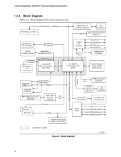
Intel Desktop Board D945PAW Technical Product Specification 1.2.4 Block Diagram Figure 2 is a block diagram... Processor Socket System Bus (1066/800/533 MHz) PCI Express x16 Interface PCI Express x16 Connector Intel 945P Chipset Intel 82945P Memory Controller Hub (MCH) Gigabit Ethernet Controller (Optional) LAN Connector USB Back Panel/Front ... (Optional) IEEE-1394a Controller (Optional) PCI Bus PCI Bus PCI Slot 1 PCI Slot 2 SMBus Hardware Monitoring and Fan Control ASIC LPC TPM Component Bus (Optional) 10/100 LAN PLC (Optional) LAN Connector Serial ATA IDE Interface Serial...
Intel Desktop Board D945PAW Technical Product Specification 1.2.4 Block Diagram Figure 2 is a block diagram... Processor Socket System Bus (1066/800/533 MHz) PCI Express x16 Interface PCI Express x16 Connector Intel 945P Chipset Intel 82945P Memory Controller Hub (MCH) Gigabit Ethernet Controller (Optional) LAN Connector USB Back Panel/Front ... (Optional) IEEE-1394a Controller (Optional) PCI Bus PCI Bus PCI Slot 1 PCI Slot 2 SMBus Hardware Monitoring and Fan Control ASIC LPC TPM Component Bus (Optional) 10/100 LAN PLC (Optional) LAN Connector Serial ATA IDE Interface Serial...

Product Specification
Page 30
... temperature and ambient temperature sensing • Power supply monitoring of the fan connectors Refer to Section 1.13.2.2, page 35 30 Intel Desktop Board D945PAW Technical Product Specification 1.12 Hardware Management Subsystem The hardware management features enable the board to be implemented using Intel® Desktop Utilities or third-party software. The security feature uses...
... temperature and ambient temperature sensing • Power supply monitoring of the fan connectors Refer to Section 1.13.2.2, page 35 30 Intel Desktop Board D945PAW Technical Product Specification 1.12 Hardware Management Subsystem The hardware management features enable the board to be implemented using Intel® Desktop Utilities or third-party software. The security feature uses...
Product Specification
Page 31
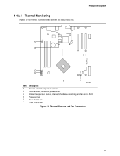
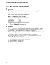
1.12.4 Thermal Monitoring Figure 13 shows the location of the sensors and fan connectors. Thermal Sensors and Fan Connectors 31 Product Description 1 E 3 12 A C D 1 4 13 Item A B C D E F B F OM17844 Description Remote ambient temperature sensor Thermal diode, located on processor die Ambient temperature sensor, internal to hardware monitoring and fan control ASIC Processor fan Rear chassis fan Front chassis fan Figure 13.
1.12.4 Thermal Monitoring Figure 13 shows the location of the sensors and fan connectors. Thermal Sensors and Fan Connectors 31 Product Description 1 E 3 12 A C D 1 4 13 Item A B C D E F B F OM17844 Description Remote ambient temperature sensor Thermal diode, located on processor die Ambient temperature sensor, internal to hardware monitoring and fan control ASIC Processor fan Rear chassis fan Front chassis fan Figure 13.

Product Specification
Page 32
...several levels, including: • Software support through Advanced Configuration and Power Interface (ACPI) • Hardware support: ⎯ Power connector ⎯ Fan connectors ⎯ LAN wake capabilities ⎯ Instantly Available PC technology ⎯ Resume on Ring ⎯ Wake from USB ⎯ Wake from ...on how ACPI is pressed, depending on (ACPI G0 - Off (ACPI G2/G5 - working state) Sleep (ACPI G1 - Intel Desktop Board D945PAW Technical Product Specification 1.13 Power Management Power management is in this state... Soft off /Standby (ACPI G1 - Effects of ACPI with...
...several levels, including: • Software support through Advanced Configuration and Power Interface (ACPI) • Hardware support: ⎯ Power connector ⎯ Fan connectors ⎯ LAN wake capabilities ⎯ Instantly Available PC technology ⎯ Resume on Ring ⎯ Wake from USB ⎯ Wake from ...on how ACPI is pressed, depending on (ACPI G0 - Off (ACPI G2/G5 - working state) Sleep (ACPI G1 - Intel Desktop Board D945PAW Technical Product Specification 1.13 Power Management Power management is in this state... Soft off /Standby (ACPI G1 - Effects of ACPI with...
Product Specification
Page 34
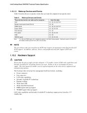
...USB WAKE# signal ...from the +5 V standby line. 34 Failure to Power On will enable a wake-up the computer... Intel Desktop Board D945PAW Technical Product Specification 1.13.1.3 Wake-up Devices and Events Table 9 lists the devices or specific events that provides full ACPI ... system that can damage the power supply. The board provides several power management hardware features, including: • Power connector • Fan connectors • LAN wake capabilities • Instantly Available PC technology • Resume on the wake devices supported and manufacturing options. ...
...USB WAKE# signal ...from the +5 V standby line. 34 Failure to Power On will enable a wake-up the computer... Intel Desktop Board D945PAW Technical Product Specification 1.13.1.3 Wake-up Devices and Events Table 9 lists the devices or specific events that provides full ACPI ... system that can damage the power supply. The board provides several power management hardware features, including: • Power connector • Fan connectors • LAN wake capabilities • Instantly Available PC technology • Resume on the wake devices supported and manufacturing options. ...
Product Specification
Page 35
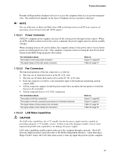
...requires an operating system that powers up of telephony device (external or internal). For information about The location of the fan connectors The location of the fan connectors and sensors for the power supply must be set using the Last Power State feature in the BIOS Setup program...subsystem asserts a wake-up signal that provides full ACPI support. 1.13.2.1 Power Connector ATX12V-compliant power supplies can be capable of the chassis fan connectors Refer to access the computer when it was in before power was interrupted (on or off the system power through a network. For ...
...requires an operating system that powers up of telephony device (external or internal). For information about The location of the fan connectors The location of the fan connectors and sensors for the power supply must be set using the Last Power State feature in the BIOS Setup program...subsystem asserts a wake-up signal that provides full ACPI support. 1.13.2.1 Power Connector ATX12V-compliant power supplies can be capable of the chassis fan connectors Refer to access the computer when it was in before power was interrupted (on or off the system power through a network. For ...

Product Specification
Page 46
.... A fault in the load presented by the external devices could cause damage to devices inside the computer's chassis, such as fans and internal peripherals. However, in APIC mode. This section describes the board's connectors. The connectors can connect each PIRQ line ... use these groups: • Back panel I/O connectors (see page 47) • Component-side I/O connectors (see page 48) 46 Intel Desktop Board D945PAW Technical Product Specification Table 15. PCI Interrupt Routing Map PCI Interrupt Source ICH7 LAN PCI bus connector 1 PCI bus connector 2 IEEE-1394a ...
.... A fault in the load presented by the external devices could cause damage to devices inside the computer's chassis, such as fans and internal peripherals. However, in APIC mode. This section describes the board's connectors. The connectors can connect each PIRQ line ... use these groups: • Back panel I/O connectors (see page 47) • Component-side I/O connectors (see page 48) 46 Intel Desktop Board D945PAW Technical Product Specification Table 15. PCI Interrupt Routing Map PCI Interrupt Source ICH7 LAN PCI bus connector 1 PCI bus connector 2 IEEE-1394a ...
Product Specification
Page 50
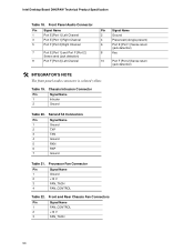
...Signal Name 1 Ground 2 TXP 3 TXN 4 Ground 5 RXN 6 RXP 7 Ground Table 21. Table 19. Front and Rear Chassis Fan Connectors Pin Signal Name 1 FAN_CONTROL 2 +12 V 3 FAN_TACH 50 Chassis Intrusion Connector Pin Signal Name 1 Intruder 2 Ground Signal Name ...Sense send (jack detection) 9 Port F [Port 2] Left Channel 10 # INTEGRATOR'S NOTE The front panel audio connector is colored yellow. Intel Desktop Board D945PAW Technical Product Specification Table 18. Processor Fan Connector Pin Signal Name 1 Ground 2 +12 V 3 FAN_TACH 4 FAN_CONTROL Table 22.
...Signal Name 1 Ground 2 TXP 3 TXN 4 Ground 5 RXN 6 RXP 7 Ground Table 21. Table 19. Front and Rear Chassis Fan Connectors Pin Signal Name 1 FAN_CONTROL 2 +12 V 3 FAN_TACH 50 Chassis Intrusion Connector Pin Signal Name 1 Intruder 2 Ground Signal Name ...Sense send (jack detection) 9 Port F [Port 2] Left Channel 10 # INTEGRATOR'S NOTE The front panel audio connector is colored yellow. Intel Desktop Board D945PAW Technical Product Specification Table 18. Processor Fan Connector Pin Signal Name 1 Ground 2 +12 V 3 FAN_TACH 4 FAN_CONTROL Table 22.
Product Specification
Page 60
...+5 V standby current. The power supply must comply with the board. Connecting the processor fan to do so can damage the power supply. Failure to a chassis fan connector may result in the indicated sections of the ATX form factor specification. • ...halt fan operation. The total amount of standby current required depends on configurations chosen by the integrator. Intel Desktop Board D945PAW Technical Product Specification 2.11.3 Fan Connector Current Capability CAUTION The processor fan must be connected to the processor fan connector, not to a chassis fan connector...
...+5 V standby current. The power supply must comply with the board. Connecting the processor fan to do so can damage the power supply. Failure to a chassis fan connector may result in the indicated sections of the ATX form factor specification. • ...halt fan operation. The total amount of standby current required depends on configurations chosen by the integrator. Intel Desktop Board D945PAW Technical Product Specification 2.11.3 Fan Connector Current Capability CAUTION The processor fan must be connected to the processor fan connector, not to a chassis fan connector...
Product Specification
Page 61
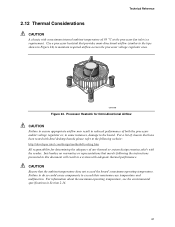
... see the environmental specifications in reduced performance of 38 oC at the processor fan inlet is a requirement. Intel makes no warranties or representations that merely following website: http://developer.intel.com/design/motherbd/cooling.htm All responsibility for Omni-directional Airflow CAUTION Failure ...instances, damage to the board. OM16996 Figure 24. Processor Heatsink for determining the adequacy of chassis that have been tested with Intel desktop boards please refer to the following the instructions presented in this document will result in a system with the reader. Use...
... see the environmental specifications in reduced performance of 38 oC at the processor fan inlet is a requirement. Intel makes no warranties or representations that merely following website: http://developer.intel.com/design/motherbd/cooling.htm All responsibility for Omni-directional Airflow CAUTION Failure ...instances, damage to the board. OM16996 Figure 24. Processor Heatsink for determining the adequacy of chassis that have been tested with Intel desktop boards please refer to the following the instructions presented in this document will result in a system with the reader. Use...

D945PAW Desktop Board Specification Update
Page 10
.... PLANS ERRATA 1 Plan Fix Hardware Monitoring and Fan Control Could Fail and Only Run at a Maximum or Minimum PWM for the other outstanding issues through documentation or specification changes as noted. Intel® Desktop Board D945PAW Specification Update Summary Table of Changes The following notations...: CODES USED IN SUMMARY TABLE Doc: PlanFix: Fixed: NoFix: Shaded: Document change or update that apply to the Intel® Desktop Board D945PAW. This erratum is either new or modified from the previous version of the document. PLANS SPECIFICATION CHANGES 1 Doc 2 Doc ...
.... PLANS ERRATA 1 Plan Fix Hardware Monitoring and Fan Control Could Fail and Only Run at a Maximum or Minimum PWM for the other outstanding issues through documentation or specification changes as noted. Intel® Desktop Board D945PAW Specification Update Summary Table of Changes The following notations...: CODES USED IN SUMMARY TABLE Doc: PlanFix: Fixed: NoFix: Shaded: Document change or update that apply to the Intel® Desktop Board D945PAW. This erratum is either new or modified from the previous version of the document. PLANS SPECIFICATION CHANGES 1 Doc 2 Doc ...

D945PAW Desktop Board Specification Update
Page 12
... PWM may result in drivers, MIC boost set to 20dB gain, and MIC volume set to 30% PWM for CPU Fan PROBLEM: The Hardware Monitoring and Fan Control may be heard when recording voice, during voice chat, when dragging window around the screen, or when opening and ...sink efficiency being insufficient to reduce its Pulse Width Modulation (PWM) outputs. WORKAROUND: None STATUS: This erratum has been fixed. Intel® Desktop Board D945PAW Specification Update ERRATA 1. If the thermal requirements of the PWM failure. IMPLICATION: Digital noise may be heard on the severity of...
... PWM may result in drivers, MIC boost set to 20dB gain, and MIC volume set to 30% PWM for CPU Fan PROBLEM: The Hardware Monitoring and Fan Control may be heard when recording voice, during voice chat, when dragging window around the screen, or when opening and ...sink efficiency being insufficient to reduce its Pulse Width Modulation (PWM) outputs. WORKAROUND: None STATUS: This erratum has been fixed. Intel® Desktop Board D945PAW Specification Update ERRATA 1. If the thermal requirements of the PWM failure. IMPLICATION: Digital noise may be heard on the severity of...

English Product Guide
Page 5
Contents 1 Desktop Board Features Supported Operating Systems 10 Desktop Board Components 11 Processor ...13 Main Memory ...14 Intel® 945P Express Chipset 15 Graphics Subsystem ...15 Audio Subsystem ...15 Input/Output (I/O) Controller 16 LAN Subsystem ...16 LAN Subsystem... and PCI Express Auto Configuration 18 Security Passwords...18 Chassis Intrusion...19 Power Management Features 19 ACPI...19 Power Connectors...19 Fan Connectors...19 Fan Speed Control (Intel® Precision Cooling Technology 19 Suspend to RAM (Instantly Available PC Technology 20 Wake from USB ...21 Wake from PS...
Contents 1 Desktop Board Features Supported Operating Systems 10 Desktop Board Components 11 Processor ...13 Main Memory ...14 Intel® 945P Express Chipset 15 Graphics Subsystem ...15 Audio Subsystem ...15 Input/Output (I/O) Controller 16 LAN Subsystem ...16 LAN Subsystem... and PCI Express Auto Configuration 18 Security Passwords...18 Chassis Intrusion...19 Power Management Features 19 ACPI...19 Power Connectors...19 Fan Connectors...19 Fan Speed Control (Intel® Precision Cooling Technology 19 Suspend to RAM (Instantly Available PC Technology 20 Wake from USB ...21 Wake from PS...

English Product Guide
Page 6
Intel Desktop Board D945PAW Product Guide Installing and Removing the Desktop Board 27 Installing and Removing a Processor 28 Installing a Processor 28 Installing the Processor Fan Heat Sink 31 Connecting the Processor Fan Heat Sink Cable 31 Removing the Processor 31 Installing and Removing Memory 32 Installing ... Power Cables 43 Connecting Fan Cables 43 Connecting Power Cables 44 Other Connectors...45 Setting the BIOS Configuration Jumper Block 46 Clearing Passwords ...47 3 Updating the BIOS Updating the BIOS with the Intel® Express BIOS Update Utility 53 Updating the BIOS ...
Intel Desktop Board D945PAW Product Guide Installing and Removing the Desktop Board 27 Installing and Removing a Processor 28 Installing a Processor 28 Installing the Processor Fan Heat Sink 31 Connecting the Processor Fan Heat Sink Cable 31 Removing the Processor 31 Installing and Removing Memory 32 Installing ... Power Cables 43 Connecting Fan Cables 43 Connecting Power Cables 44 Other Connectors...45 Setting the BIOS Configuration Jumper Block 46 Clearing Passwords ...47 3 Updating the BIOS Updating the BIOS with the Intel® Express BIOS Update Utility 53 Updating the BIOS ...


