

Product Guide
Page 5
Contents 1 Desktop Board Features 9 Manufacturing Options ...11 Supported Operating Systems 11 Desktop Board Components 12 Processor...16 Main Memory ...17 Intel® 945G Express Chipset 18 Graphics Subsystem ...18 Audio Subsystem ...18 Input/Output (I/O) Controller 19 LAN Subsystem ...19 LAN...22 Security Passwords ...22 Chassis Intrusion...23 Power Management Features 23 ACPI...23 Power Connectors...23 Fan Connectors...23 Fan Speed Control (Intel® Precision Cooling Technology 23 Suspend to RAM (Instantly Available PC Technology 24 Wake from USB...24 Wake from PS/2 Keyboard/Mouse...
Contents 1 Desktop Board Features 9 Manufacturing Options ...11 Supported Operating Systems 11 Desktop Board Components 12 Processor...16 Main Memory ...17 Intel® 945G Express Chipset 18 Graphics Subsystem ...18 Audio Subsystem ...18 Input/Output (I/O) Controller 19 LAN Subsystem ...19 LAN...22 Security Passwords ...22 Chassis Intrusion...23 Power Management Features 23 ACPI...23 Power Connectors...23 Fan Connectors...23 Fan Speed Control (Intel® Precision Cooling Technology 23 Suspend to RAM (Instantly Available PC Technology 24 Wake from USB...24 Wake from PS/2 Keyboard/Mouse...
Product Guide
Page 6
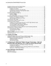
... Requires Microsoft Windows* XP or 2000 and SATA Hard Drive(s) Configuring the BIOS for RAID (Intel® Matrix Storage Technology) - Intel Desktop Board D945GNT/D945GTP Product Guide Installing and Removing the Desktop Board 31 Installing and Removing a Processor 32 Installing a... Processor 32 Installing the Processor Fan Heat Sink 35 Connecting the Processor Fan Heat Sink Cable 35 Removing the Processor 35 Installing and Removing Memory...
... Requires Microsoft Windows* XP or 2000 and SATA Hard Drive(s) Configuring the BIOS for RAID (Intel® Matrix Storage Technology) - Intel Desktop Board D945GNT/D945GTP Product Guide Installing and Removing the Desktop Board 31 Installing and Removing a Processor 32 Installing a... Processor 32 Installing the Processor Fan Heat Sink 35 Connecting the Processor Fan Heat Sink Cable 35 Removing the Processor 35 Installing and Removing Memory...
Product Guide
Page 9
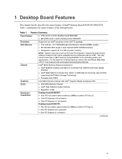
... may result in less than 4 GB of Intel® Desktop Board D945GNT/D945GTP. Table 1 summarizes the major features of system memory NOTE: System resources (such as PCI and PCI Express*) require physical memory address locations that reduce available memory addresses above 3 GB. Feature Summary Form Factors Processor Main Memory Chipset Graphics Audio Expansion Capabilities • ATX...
... may result in less than 4 GB of Intel® Desktop Board D945GNT/D945GTP. Table 1 summarizes the major features of system memory NOTE: System resources (such as PCI and PCI Express*) require physical memory address locations that reduce available memory addresses above 3 GB. Feature Summary Form Factors Processor Main Memory Chipset Graphics Audio Expansion Capabilities • ATX...
Product Guide
Page 10
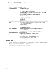
...• PS/2* keyboard and mouse ports • Intel® Platform Innovation Framework for extensible firmware interface • 4 Mbit symmetrical flash memory • Support for SMBIOS • Intel® Rapid BIOS Boot • Intel® Express BIOS Update Power Management • Support...range values Related Links: For more information about desktop board D945GNT/D945GTP, including the Technical Product Specification (TPS), BIOS updates, and device drivers, go to: http://support.intel.com/support/motherboards/desktop/ 10 Intel Desktop Board D945GNT/D945GTP Product Guide Table 1.
...• PS/2* keyboard and mouse ports • Intel® Platform Innovation Framework for extensible firmware interface • 4 Mbit symmetrical flash memory • Support for SMBIOS • Intel® Rapid BIOS Boot • Intel® Express BIOS Update Power Management • Support...range values Related Links: For more information about desktop board D945GNT/D945GTP, including the Technical Product Specification (TPS), BIOS updates, and device drivers, go to: http://support.intel.com/support/motherboards/desktop/ 10 Intel Desktop Board D945GNT/D945GTP Product Guide Table 1.
Product Guide
Page 17
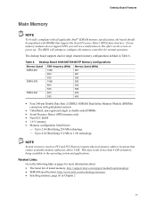
...System resources (such as PCI and PCI Express) require physical memory address locations that support the Serial Presence Detect (SPD) data structure. Desktop Board D945GNT/D945GTP Memory Configurations Memory Speed FSB frequency (MHz) Memory Speed (MHz) DDR2-667 1066 667 800 667 533 ...than 4 GB of tested memory, http://support.intel.com/support/motherboards/desktop/ • SDRAM specifications, http://www.intel.com/technology/memory/ • Installing memory, page 36 in Table 6. Related Links: Go to the operating system and applications. If your memory modules do not support ...
...System resources (such as PCI and PCI Express) require physical memory address locations that support the Serial Presence Detect (SPD) data structure. Desktop Board D945GNT/D945GTP Memory Configurations Memory Speed FSB frequency (MHz) Memory Speed (MHz) DDR2-667 1066 667 800 667 533 ...than 4 GB of tested memory, http://support.intel.com/support/motherboards/desktop/ • SDRAM specifications, http://www.intel.com/technology/memory/ • Installing memory, page 36 in Table 6. Related Links: Go to the operating system and applications. If your memory modules do not support ...

Product Guide
Page 18
...connectors that are configurable through the drivers of the following devices: • Intel 82945G Graphics and Memory Controller Hub (GMCH) with Digital Media Interface • Intel 82801GB I/O Controller Hub (ICH7) or Intel 82801GR I /O Controller Hub (ICH7R) • SigmaTel STAC9220 or STAC9223 audio...; S/N (signal-to the following link for more information about the Intel 945G Express Chipset: http://developer.intel.com/design/nav/pcserver.htm Graphics Subsystem Desktop board D945GNT/D945GTP includes the following connectors: • Front panel audio connector, including functionality...
...connectors that are configurable through the drivers of the following devices: • Intel 82945G Graphics and Memory Controller Hub (GMCH) with Digital Media Interface • Intel 82801GB I/O Controller Hub (ICH7) or Intel 82801GR I /O Controller Hub (ICH7R) • SigmaTel STAC9220 or STAC9223 audio...; S/N (signal-to the following link for more information about the Intel 945G Express Chipset: http://developer.intel.com/design/nav/pcserver.htm Graphics Subsystem Desktop board D945GNT/D945GTP includes the following connectors: • Front panel audio connector, including functionality...

Product Guide
Page 24
...wake-up device or event, the system quickly returns to support multiple wake events from an ACPI S1 or S3 state. 24 Intel Desktop Board D945GNT/D945GTP Product Guide Suspend to RAM (Instantly Available PC Technology) CAUTIONS For Instantly Available PC technology, the 5 V standby line for the...4. Power supplies used with this feature can damage the power supply and/or effect ACPI S3 sleep state functionality. This includes the memory modules and PCI bus connectors, even when the computer appears to support the standard Instantly Available (ACPI S3 sleep state) configuration. ...
...wake-up device or event, the system quickly returns to support multiple wake events from an ACPI S1 or S3 state. 24 Intel Desktop Board D945GNT/D945GTP Product Guide Suspend to RAM (Instantly Available PC Technology) CAUTIONS For Instantly Available PC technology, the 5 V standby line for the...4. Power supplies used with this feature can damage the power supply and/or effect ACPI S3 sleep state functionality. This includes the memory modules and PCI bus connectors, even when the computer appears to support the standard Instantly Available (ACPI S3 sleep state) configuration. ...

Product Guide
Page 27
... personal injury or equipment damage. NOTE Refer to : • Install the I/O shield • Install and remove the desktop board • Install and remove a processor and memory • Install and remove a PCI Express x16 card • Connect the IDE and Serial ATA cables • Connect internal headers • Set up flexible 6-channel...
... personal injury or equipment damage. NOTE Refer to : • Install the I/O shield • Install and remove the desktop board • Install and remove a processor and memory • Install and remove a PCI Express x16 card • Connect the IDE and Serial ATA cables • Connect internal headers • Set up flexible 6-channel...
Product Guide
Page 36
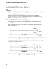
Intel Desktop Board D945GNT/D945GTP Product Guide Installing and Removing Memory NOTE To be used, install another matched pair of both channels A and B (see Figure 15). 256 MB, 533 MHz 512 MB, 533 MHz 256 MB, 533 MHz 512 MB, 533 MHz Channel A Channel B Figure 15. Guidelines for Dual Channel Memory... support the Serial Presence Detect (SPD) data structure. You can access the PC Serial Presence Detect Specification at: http://www.intel.com/technology/memory/ddr/specs/dda18c32_64_128x72ag_a.pdf The desktop board has four 240-pin DDR2 DIMM sockets arranged as DIMM 0 (blue) and DIMM ...
Intel Desktop Board D945GNT/D945GTP Product Guide Installing and Removing Memory NOTE To be used, install another matched pair of both channels A and B (see Figure 15). 256 MB, 533 MHz 512 MB, 533 MHz 256 MB, 533 MHz 512 MB, 533 MHz Channel A Channel B Figure 15. Guidelines for Dual Channel Memory... support the Serial Presence Detect (SPD) data structure. You can access the PC Serial Presence Detect Specification at: http://www.intel.com/technology/memory/ddr/specs/dda18c32_64_128x72ag_a.pdf The desktop board has four 240-pin DDR2 DIMM sockets arranged as DIMM 0 (blue) and DIMM ...

Product Guide
Page 37
Dual Configuration Example 3 DIMM 0 DIMM 1 DIMM 0 DIMM 1 NOTE All other memory configurations will result in either DIMM 0 or DIMM 1 of channel B (see Figure 16). 256 MB, 533 MHz 256 MB, 533 MHz 512 MB, 533 MHz Channel A Channel B Figure 16. Install a DIMM equal in speed and total size of channel A. Installing and Replacing Desktop Board Components Three DIMMs Install a matched pair of DIMMs equal in speed and size in DIMM 0 (blue) and DIMM 1 (black) of the DIMMs installed in channel A in single channel memory operation. 37
Dual Configuration Example 3 DIMM 0 DIMM 1 DIMM 0 DIMM 1 NOTE All other memory configurations will result in either DIMM 0 or DIMM 1 of channel B (see Figure 16). 256 MB, 533 MHz 256 MB, 533 MHz 512 MB, 533 MHz Channel A Channel B Figure 16. Install a DIMM equal in speed and total size of channel A. Installing and Replacing Desktop Board Components Three DIMMs Install a matched pair of DIMMs equal in speed and size in DIMM 0 (blue) and DIMM 1 (black) of the DIMMs installed in channel A in single channel memory operation. 37

Product Guide
Page 38
...avoid interference with the DIMM retaining clips from its anti-static package. 7. Reinstall the PCI Express card if it interferes with the memory retention mechanism. 1. Turn off the computer and disconnect the AC power cord. 3. Remove the computer's cover and locate the DIMM... Figure 17. Turn off all peripheral devices connected to installing the DIMMs. 11. Installing a DIMM OM17617 4. Intel Desktop Board D945GNT/D945GTP Product Guide Installing DIMMs NOTE Install memory in Figure 17). 8. Holding the DIMM by the edges, remove it from being easily opened and closed. ...
...avoid interference with the DIMM retaining clips from its anti-static package. 7. Reinstall the PCI Express card if it interferes with the memory retention mechanism. 1. Turn off the computer and disconnect the AC power cord. 3. Remove the computer's cover and locate the DIMM... Figure 17. Turn off all peripheral devices connected to installing the DIMMs. 11. Installing a DIMM OM17617 4. Intel Desktop Board D945GNT/D945GTP Product Guide Installing DIMMs NOTE Install memory in Figure 17). 8. Holding the DIMM by the edges, remove it from being easily opened and closed. ...

Product Guide
Page 53
... einer neuen Batterie besteht Explosionsgefahr. Installing and Replacing Desktop Board Components Replacing the Battery A coin-cell battery (CR2032) powers the real-time clock and CMOS memory. Replace the battery with an incorrect type. Figure 27 on mahdollista. VIKTIGT! Batterier ska kasseras enligt de lokala miljövårdsbestämmelserna. Kä...
... einer neuen Batterie besteht Explosionsgefahr. Installing and Replacing Desktop Board Components Replacing the Battery A coin-cell battery (CR2032) powers the real-time clock and CMOS memory. Replace the battery with an incorrect type. Figure 27 on mahdollista. VIKTIGT! Batterier ska kasseras enligt de lokala miljövårdsbestämmelserna. Kä...
Product Guide
Page 59
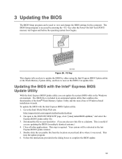
... you how to update the BIOS by pressing the key after the Power-On Self-Test (POST) memory test begins and before the operating system boot begins. Go to the D945GNT/D945GTP page, click "[view] Latest BIOS updates," and select the Express BIOS Update utility file. 3. F2... Key This chapter tells you are updating the BIOS for the computer. Follow the instructions provided in an automated update utility that combines the functionality of the Intel® Flash Memory ...
... you how to update the BIOS by pressing the key after the Power-On Self-Test (POST) memory test begins and before the operating system boot begins. Go to the D945GNT/D945GTP page, click "[view] Latest BIOS updates," and select the Express BIOS Update utility file. 3. F2... Key This chapter tells you are updating the BIOS for the computer. Follow the instructions provided in an automated update utility that combines the functionality of the Intel® Flash Memory ...
Product Guide
Page 60
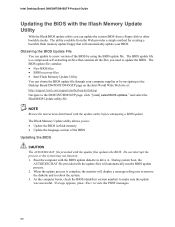
...the BIOS update diskette in flash memory • Update the language section of the BIOS by navigating to the Desktop Board D945GNT/D945GTP page on the Intel World Wide Web site at: http://support.intel.com/support/motherboards/desktop Navigate to the D945GNT/D945GTP page, click "[view] Latest BIOS... updates," and select the Iflash BIOS Update utility file. Intel Desktop Board D945GNT/D945GTP Product Guide Updating the BIOS with the Iflash Memory Update Utility With the Iflash BIOS update utility you to: • Update the BIOS in drive A. The utility available ...
...the BIOS update diskette in flash memory • Update the language section of the BIOS by navigating to the Desktop Board D945GNT/D945GTP page on the Intel World Wide Web site at: http://support.intel.com/support/motherboards/desktop Navigate to the D945GNT/D945GTP page, click "[view] Latest BIOS... updates," and select the Iflash BIOS Update utility file. Intel Desktop Board D945GNT/D945GTP Product Guide Updating the BIOS with the Iflash Memory Update Utility With the Iflash BIOS update utility you to: • Update the BIOS in drive A. The utility available ...

Product Guide
Page 63
... your volume) and press . 7. ensure RAID is selected. 4. Then save your settings by pressing the key after the Power-On-Self-Test (POST) memory tests begin. 3. Press and enter the RAID Configuration Utility. 2. Use the arrow keys to Advanced Drive Configuration Configure SATA as; Go to select RAID 0... or RAID 1 (if only two SATA drives are available), RAID 5 and RAID 10 (these options will see the following Intel Matrix Storage Manager option ROM status message on the remaining portion of your system and attach two or more than the maximum volume size, you...
... your volume) and press . 7. ensure RAID is selected. 4. Then save your settings by pressing the key after the Power-On-Self-Test (POST) memory tests begin. 3. Press and enter the RAID Configuration Utility. 2. Use the arrow keys to Advanced Drive Configuration Configure SATA as; Go to select RAID 0... or RAID 1 (if only two SATA drives are available), RAID 5 and RAID 10 (these options will see the following Intel Matrix Storage Manager option ROM status message on the remaining portion of your system and attach two or more than the maximum volume size, you...

Product Guide
Page 65
... SINGLE_BIT_ECC_ERROR CMOS_BATTERY_ERROR CMOS_CHECKSUM_ERROR CMOS_TIMER_ERROR MEMORY_SIZE_DECREASE_ERROR INTRUDER_DETECTION_ERROR SPD_TOLER_ERROR MEM_OPTIMAL_ERROR Explanation CPU was opened. The installed amount of memory in Channel B. Maximum memory performance is achieved with equal amounts of the BIOS error messages. Table 15 lists the BIOS codes...has detected that the system date/time has not been set. DDR2 533 MHz memory assumed at slowest timings. A Error Messages and Indicators Desktop board D945GNT/D945GTP reports POST errors in two ways: • By sounding a beep code ...
... SINGLE_BIT_ECC_ERROR CMOS_BATTERY_ERROR CMOS_CHECKSUM_ERROR CMOS_TIMER_ERROR MEMORY_SIZE_DECREASE_ERROR INTRUDER_DETECTION_ERROR SPD_TOLER_ERROR MEM_OPTIMAL_ERROR Explanation CPU was opened. The installed amount of memory in Channel B. Maximum memory performance is achieved with equal amounts of the BIOS error messages. Table 15 lists the BIOS codes...has detected that the system date/time has not been set. DDR2 533 MHz memory assumed at slowest timings. A Error Messages and Indicators Desktop board D945GNT/D945GTP reports POST errors in two ways: • By sounding a beep code ...

Product Specification
Page 5
... Manufacturing Options 11 1.1.3 Board Layout 12 1.1.4 Block Diagram 14 1.2 Online Support ...15 1.3 Processor ...15 1.4 System Memory ...16 1.4.1 Memory Configurations 17 1.5 Intel® 945G Chipset ...21 1.5.1 Intel 945G Graphics Subsystem 21 1.5.2 USB ...23 1.5.3 IDE Support 24 1.5.4 Real-Time Clock, CMOS SRAM, and Battery 26 ....1 LAN Subsystem Software 31 1.10.2 10/100 Mbits/sec LAN Subsystem 31 1.10.3 Gigabit LAN Subsystem 32 1.10.4 Intel® Active Management Technology (Optional 33 1.10.5 Alert Standard Format (ASF) Support (Optional 35 1.11 Hardware Management Subsystem...
... Manufacturing Options 11 1.1.3 Board Layout 12 1.1.4 Block Diagram 14 1.2 Online Support ...15 1.3 Processor ...15 1.4 System Memory ...16 1.4.1 Memory Configurations 17 1.5 Intel® 945G Chipset ...21 1.5.1 Intel 945G Graphics Subsystem 21 1.5.2 USB ...23 1.5.3 IDE Support 24 1.5.4 Real-Time Clock, CMOS SRAM, and Battery 26 ....1 LAN Subsystem Software 31 1.10.2 10/100 Mbits/sec LAN Subsystem 31 1.10.3 Gigabit LAN Subsystem 32 1.10.4 Intel® Active Management Technology (Optional 33 1.10.5 Alert Standard Format (ASF) Support (Optional 35 1.11 Hardware Management Subsystem...

Product Specification
Page 6
Intel Desktop Board D945GTP Technical Product Specification 2 Technical Reference 2.1 Introduction ...45 2.2 Memory Resources ...45 2.2.1 Addressable Memory 45 2.2.2 Memory Map 47 2.3 DMA Channels ...47 2.4 Fixed I/O Map...48 2.5 PCI Configuration Space Map 49 2.6 Interrupts...15.4 Recycling Considerations 77 2.15.5 Product Certification Markings (Board Level 78 3 Overview of BIOS Features 3.1 Introduction ...79 3.2 BIOS Flash Memory Organization 80 3.3 Resource Configuration 80 3.3.1 PCI Autoconfiguration 80 3.3.2 PCI IDE Support 80 3.4 System Management BIOS (SMBIOS 81 3.5 Legacy USB...
Intel Desktop Board D945GTP Technical Product Specification 2 Technical Reference 2.1 Introduction ...45 2.2 Memory Resources ...45 2.2.1 Addressable Memory 45 2.2.2 Memory Map 47 2.3 DMA Channels ...47 2.4 Fixed I/O Map...48 2.5 PCI Configuration Space Map 49 2.6 Interrupts...15.4 Recycling Considerations 77 2.15.5 Product Certification Markings (Board Level 78 3 Overview of BIOS Features 3.1 Introduction ...79 3.2 BIOS Flash Memory Organization 80 3.3 Resource Configuration 80 3.3.1 PCI Autoconfiguration 80 3.3.2 PCI IDE Support 80 3.4 System Management BIOS (SMBIOS 81 3.5 Legacy USB...

Product Specification
Page 7
...Codes 4.1 Speaker ...87 4.2 BIOS Beep Codes...87 4.3 BIOS Error Messages 87 4.4 Port 80h POST Codes 88 Figures 1. Detailed System Memory Address Map 46 18. Location of the Standby Power Indicator LED 44 17. Single Channel (Asymmetric) Mode Configuration with One DIMM 20 8.... 62 22. LAN Connector LED Locations 33 15. Back Panel Connectors for 6-Channel (5.1) Audio Subsystem 55 20. Board Components ...12 2. Memory Channel and DIMM Configuration 17 4. Dual Channel (Interleaved) Mode Configuration with the 8-Channel (7.1) Audio Subsystem 67 27. Back Panel Connectors for...
...Codes 4.1 Speaker ...87 4.2 BIOS Beep Codes...87 4.3 BIOS Error Messages 87 4.4 Port 80h POST Codes 88 Figures 1. Detailed System Memory Address Map 46 18. Location of the Standby Power Indicator LED 44 17. Single Channel (Asymmetric) Mode Configuration with One DIMM 20 8.... 62 22. LAN Connector LED Locations 33 15. Back Panel Connectors for 6-Channel (5.1) Audio Subsystem 55 20. Board Components ...12 2. Memory Channel and DIMM Configuration 17 4. Dual Channel (Interleaved) Mode Configuration with the 8-Channel (7.1) Audio Subsystem 67 27. Back Panel Connectors for...
Product Specification
Page 8
LAN Connector LED States 33 7. Wake-up Devices and Events 40 10. System Memory Map 47 11. Back Panel Connectors Shown in Figure 1 13 4. Front Panel Connector 62 29. States for a One-Color Power LED...DMA Channels ...47 12. Chassis Intrusion Connector 58 21. Processor Fan Connector 59 24. Thermal Considerations for Components 73 35. Intel Desktop Board D945GTP Technical Product Specification Tables 1. Supported Memory Configurations 16 5. Interrupts ...50 15. ATX12V Power Connector 60 27. Product Certification Markings 78 39. Back Panel Connectors Shown ...
LAN Connector LED States 33 7. Wake-up Devices and Events 40 10. System Memory Map 47 11. Back Panel Connectors Shown in Figure 1 13 4. Front Panel Connector 62 29. States for a One-Color Power LED...DMA Channels ...47 12. Chassis Intrusion Connector 58 21. Processor Fan Connector 59 24. Thermal Considerations for Components 73 35. Intel Desktop Board D945GTP Technical Product Specification Tables 1. Supported Memory Configurations 16 5. Interrupts ...50 15. ATX12V Power Connector 60 27. Product Certification Markings 78 39. Back Panel Connectors Shown ...


