

Product Guide
Page 5
Contents 1 Desktop Board Features 9 Manufacturing Options ...11 Supported Operating Systems 11 Desktop Board Components 12 Processor...16 Main Memory ...17 Intel® 945G Express Chipset 18 Graphics Subsystem ...18 Audio Subsystem ...18 Input/Output (I/O) Controller 19 LAN Subsystem ...19 LAN...22 Security Passwords ...22 Chassis Intrusion...23 Power Management Features 23 ACPI...23 Power Connectors...23 Fan Connectors...23 Fan Speed Control (Intel® Precision Cooling Technology 23 Suspend to RAM (Instantly Available PC Technology 24 Wake from USB...24 Wake from PS/2 Keyboard/Mouse...
Contents 1 Desktop Board Features 9 Manufacturing Options ...11 Supported Operating Systems 11 Desktop Board Components 12 Processor...16 Main Memory ...17 Intel® 945G Express Chipset 18 Graphics Subsystem ...18 Audio Subsystem ...18 Input/Output (I/O) Controller 19 LAN Subsystem ...19 LAN...22 Security Passwords ...22 Chassis Intrusion...23 Power Management Features 23 ACPI...23 Power Connectors...23 Fan Connectors...23 Fan Speed Control (Intel® Precision Cooling Technology 23 Suspend to RAM (Instantly Available PC Technology 24 Wake from USB...24 Wake from PS/2 Keyboard/Mouse...
Product Guide
Page 6
Intel Desktop Board D945GNT/D945GTP Product Guide Installing and Removing the Desktop Board 31 Installing and Removing a Processor 32 Installing a Processor 32 Installing the Processor Fan Heat Sink 35 Connecting the Processor Fan Heat Sink Cable 35 Removing the Processor 35 Installing and Removing Memory 36 Installing DIMMs... Cable 41 Connecting the Serial ATA (SATA) Cable 42 Connecting Internal Headers 43 Installing a Front Panel Audio Solution for Intel® High Definition Audio 44 Connecting Hi-Speed USB 2.0 Headers 45 Connecting IEEE 1394a Headers (Optional 45 Connecting the ...
Intel Desktop Board D945GNT/D945GTP Product Guide Installing and Removing the Desktop Board 31 Installing and Removing a Processor 32 Installing a Processor 32 Installing the Processor Fan Heat Sink 35 Connecting the Processor Fan Heat Sink Cable 35 Removing the Processor 35 Installing and Removing Memory 36 Installing DIMMs... Cable 41 Connecting the Serial ATA (SATA) Cable 42 Connecting Internal Headers 43 Installing a Front Panel Audio Solution for Intel® High Definition Audio 44 Connecting Hi-Speed USB 2.0 Headers 45 Connecting IEEE 1394a Headers (Optional 45 Connecting the ...

Product Guide
Page 7
...Location of Other Connectors on Desktop Board D945GNT/D945GTP 50 26. Desktop Board D945GNT Components 12 2. Location of the BIOS Configuration Jumper 51 27. Intel Desktop Board D945GTP Components 14 3. Remove the Processor from the Protective Processor Cover/Do Not Touch 33 11. Connecting the... Serial ATA Cable 42 21. F2 Key ...59 vii Install Processor ...34 12. Installing the I/O Shield ...
...Location of Other Connectors on Desktop Board D945GNT/D945GTP 50 26. Desktop Board D945GNT Components 12 2. Location of the BIOS Configuration Jumper 51 27. Intel Desktop Board D945GTP Components 14 3. Remove the Processor from the Protective Processor Cover/Do Not Touch 33 11. Connecting the... Serial ATA Cable 42 21. F2 Key ...59 vii Install Processor ...34 12. Installing the I/O Shield ...
Product Guide
Page 9
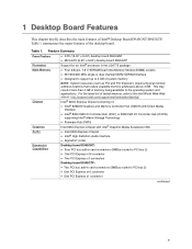
...Audio Expansion Capabilities • ATX (12.00" x 9.60") desktop board D945GNT • MicroATX (9.60" x 9.60") desktop board D945GTP Support for an Intel® processor in card connectors (SMBus routed to PCI bus 2) • One PCI Express x16 connector • One PCI Express x1 connector continued... 9 This may result in less than 4 GB of Intel® Desktop Board D945GNT/D945GTP. Table 1. 1 Desktop Board Features This...
...Audio Expansion Capabilities • ATX (12.00" x 9.60") desktop board D945GNT • MicroATX (9.60" x 9.60") desktop board D945GTP Support for an Intel® processor in card connectors (SMBus routed to PCI bus 2) • One PCI Express x16 connector • One PCI Express x1 connector continued... 9 This may result in less than 4 GB of Intel® Desktop Board D945GNT/D945GTP. Table 1. 1 Desktop Board Features This...
Product Guide
Page 13
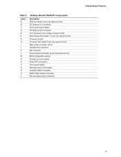
... fan header (4-pin, fan speed control) PCI Express x1 connectors Front panel audio header PCI Express x16 connector 12 V processor core voltage connector (2x2) Rear chassis fan header 1 (3-pin, fan speed control) Processor socket Processor fan header (4-pin, fan speed control) Main power connector (2x12) Diskette drive connector IDE connector Front chassis fan...
... fan header (4-pin, fan speed control) PCI Express x1 connectors Front panel audio header PCI Express x16 connector 12 V processor core voltage connector (2x2) Rear chassis fan header 1 (3-pin, fan speed control) Processor socket Processor fan header (4-pin, fan speed control) Main power connector (2x12) Diskette drive connector IDE connector Front chassis fan...

Product Guide
Page 15
... following links for more information about: • Desktop board D945GNT/D945GTP • Supported processors • Audio software and utilities • LAN software and drivers http://www.intel.com/design/motherbd http://support.intel.com/support/motherboards/desktop http://support.intel.com/support/motherboards/desktop http://www.intel.com/design/motherbd http://www.intel.com/design/motherbd 15
... following links for more information about: • Desktop board D945GNT/D945GTP • Supported processors • Audio software and utilities • LAN software and drivers http://www.intel.com/design/motherbd http://support.intel.com/support/motherboards/desktop http://support.intel.com/support/motherboards/desktop http://www.intel.com/design/motherbd http://www.intel.com/design/motherbd 15
Product Guide
Page 16
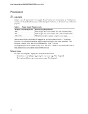
... pages for 10mS ATX12V (version 2.0 or greater) compliant power supply Desktop board D945GNT/D945GTP supports an Intel processor in the LGA775 package. Processors are not included with the desktop board and must be purchased separately. Table 5. Intel Desktop Board D945GNT/D945GTP Product Guide Processor CAUTION Failure to use the appropriate power supply (below) and/or not connecting...
... pages for 10mS ATX12V (version 2.0 or greater) compliant power supply Desktop board D945GNT/D945GTP supports an Intel processor in the LGA775 package. Processors are not included with the desktop board and must be purchased separately. Table 5. Intel Desktop Board D945GNT/D945GTP Product Guide Processor CAUTION Failure to use the appropriate power supply (below) and/or not connecting...
Product Guide
Page 21
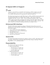
... PCI Express x1 add-in cards ⎯ Four PCI add-in cards • Desktop board D945GTP: ⎯ One PCI Express x16 add-in card ⎯ One PCI Express x1 add-in...2.0 headers. Enhanced IDE Interface The ICH7's IDE interface handles the exchange of information between the processor and peripheral devices like hard disks, CD-ROM drives, and Iomega Zip* drives inside the computer... USB 1.1 speeds. Desktop boards with USB 1.1 devices. USB 2.0 ports are backward compatible with ICH7R support Intel Matrix Storage Technology (NCQ, Hot Plug, RAID 0, 1, 10, 5, and Matrix RAID). Desktop Board Features...
... PCI Express x1 add-in cards ⎯ Four PCI add-in cards • Desktop board D945GTP: ⎯ One PCI Express x16 add-in card ⎯ One PCI Express x1 add-in...2.0 headers. Enhanced IDE Interface The ICH7's IDE interface handles the exchange of information between the processor and peripheral devices like hard disks, CD-ROM drives, and Iomega Zip* drives inside the computer... USB 1.1 speeds. Desktop boards with USB 1.1 devices. USB 2.0 ports are backward compatible with ICH7R support Intel Matrix Storage Technology (NCQ, Hot Plug, RAID 0, 1, 10, 5, and Matrix RAID). Desktop Board Features...
Product Guide
Page 23
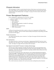
...chassis fan speed control features can be connected to the chassis intrusion header on page 49 for the location of ACPI with Intel® boxed processors. Desktop Board Features Chassis Intrusion The board supports a chassis security feature that can be disabled independently through the desktop board BIOS...desktop board has three power connectors. Desktop board D945GNT has three chassis fan headers (one 4-pin and two 3-pin). Desktop board D945GTP has two chassis fan headers (two 3-pin). The overall system noise reduction will result in chassis fans always operating at the minimum necessary ...
...chassis fan speed control features can be connected to the chassis intrusion header on page 49 for the location of ACPI with Intel® boxed processors. Desktop Board Features Chassis Intrusion The board supports a chassis security feature that can be disabled independently through the desktop board BIOS...desktop board has three power connectors. Desktop board D945GNT has three chassis fan headers (one 4-pin and two 3-pin). Desktop board D945GTP has two chassis fan headers (two 3-pin). The overall system noise reduction will result in chassis fans always operating at the minimum necessary ...

Product Guide
Page 27
... Appendix B for using and modifying electronic equipment. NOTE Refer to : • Install the I/O shield • Install and remove the desktop board • Install and remove a processor and memory • Install and remove a PCI Express x16 card • Connect the IDE and Serial ATA cables • Connect internal headers • Set up...
... Appendix B for using and modifying electronic equipment. NOTE Refer to : • Install the I/O shield • Install and remove the desktop board • Install and remove a processor and memory • Install and remove a PCI Express x16 card • Connect the IDE and Serial ATA cables • Connect internal headers • Set up...

Product Guide
Page 28
...connectors • Sharp pins on printed circuit assemblies • Rough edges and sharp corners on the chassis • Hot components (like processors, voltage regulators, and heat sinks) • Damage to wires that could be hazardous 28 If such a station is not available, you...cause a short circuit Observe all warnings and cautions in this board. Perform the procedures described in the installation instructions. Intel Desktop Board D945GNT/D945GTP Product Guide Follow these guidelines before you begin: • Always follow these instructions and the instructions provided by wearing...
...connectors • Sharp pins on printed circuit assemblies • Rough edges and sharp corners on the chassis • Hot components (like processors, voltage regulators, and heat sinks) • Damage to wires that could be hazardous 28 If such a station is not available, you...cause a short circuit Observe all warnings and cautions in this board. Perform the procedures described in the installation instructions. Intel Desktop Board D945GNT/D945GTP Product Guide Follow these guidelines before you begin: • Always follow these instructions and the instructions provided by wearing...

Product Guide
Page 32
... 24). Lift Socket Lever 3. Lift the Load Plate and Don't Touch the Socket Contacts 32 Intel Desktop Board D945GNT/D945GTP Product Guide Installing and Removing a Processor Instructions on how to install a processor to do so could damage the processor and the board. Failure to the desktop board are given below. Do not touch the socket...
... 24). Lift Socket Lever 3. Lift the Load Plate and Don't Touch the Socket Contacts 32 Intel Desktop Board D945GNT/D945GTP Product Guide Installing and Removing a Processor Instructions on how to install a processor to do so could damage the processor and the board. Failure to the desktop board are given below. Do not touch the socket...

Product Guide
Page 33
... the socket. Do not discard the protective socket cover. Always replace the processor back to touch the bottom of the processor (see Figure 9, E). Installing and Replacing Desktop Board Components 4. Remove the Processor from the socket. Do not discard the protective processor cover. Remove the plastic protective socket cover from the load plate (see Figure...
... the socket. Do not discard the protective socket cover. Always replace the processor back to touch the bottom of the processor (see Figure 9, E). Installing and Replacing Desktop Board Components 4. Remove the Processor from the socket. Do not discard the protective processor cover. Remove the plastic protective socket cover from the load plate (see Figure...

Product Guide
Page 34
... down on the load plate (Figure 12, I OM17215 Figure 12. G G H F H F Figure 11. J I ), close and engage the socket lever (Figure 12, J). Intel Desktop Board D945GNT/D945GTP Product Guide 6. Hold the processor with the socket see Figure 11, F). Align notches (see Figure 11, G) with your thumb and index fingers oriented as shown in the socket...
... down on the load plate (Figure 12, I OM17215 Figure 12. G G H F H F Figure 11. J I ), close and engage the socket lever (Figure 12, J). Intel Desktop Board D945GNT/D945GTP Product Guide 6. Hold the processor with the socket see Figure 11, F). Align notches (see Figure 11, G) with your thumb and index fingers oriented as shown in the socket...
Product Guide
Page 35
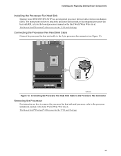
... Desktop board D945GNT/D945GTP has an integrated processor fan heat sink retention mechanism (RM). Connecting the Processor Fan Heat Sink Cable to the Processor Fan Connector Removing the Processor For instruction on how to attach the processor fan heat sink to the integrated processor fan heat sink RM, refer to the boxed processor manual or the Intel World Wide...
... Desktop board D945GNT/D945GTP has an integrated processor fan heat sink retention mechanism (RM). Connecting the Processor Fan Heat Sink Cable to the Processor Fan Connector Removing the Processor For instruction on how to attach the processor fan heat sink to the integrated processor fan heat sink RM, refer to the boxed processor manual or the Intel World Wide...

Product Guide
Page 48
Connect chassis fan cables to the 4-pin processor fan header on the board. Connect the processor's fan heat sink cable to the 3-pin fan headers. 43 2 1 A 43 2 1 B OR 3 21 A 3 21 B Figure 23. Intel Desktop Board D945GNT/D945GTP Product Guide Connecting Fan and Power Cables Connecting Fan Cables Figure 23 shows the location of Fan Headers OM17621 48 Location of the fan headers.
Connect chassis fan cables to the 4-pin processor fan header on the board. Connect the processor's fan heat sink cable to the 3-pin fan headers. 43 2 1 A 43 2 1 B OR 3 21 A 3 21 B Figure 23. Intel Desktop Board D945GNT/D945GTP Product Guide Connecting Fan and Power Cables Connecting Fan Cables Figure 23 shows the location of Fan Headers OM17621 48 Location of the fan headers.

Product Guide
Page 49
Connect the 12 V processor core voltage power supply cable to the 2x12 connector. 49 See Table 5 on page 27. 2. Connecting 2x12 Power Supply Cables OM17622 1. Connect the main power supply cable to the 2x2 connector. 3. Intel R 82945 (GMCH) R Intel 82801 (ICH7) 1 Channel A DIMM 0 2 Figure 24. Installing and Replacing Desktop Board Components Connecting Power Cables...
Connect the 12 V processor core voltage power supply cable to the 2x12 connector. 49 See Table 5 on page 27. 2. Connecting 2x12 Power Supply Cables OM17622 1. Connect the main power supply cable to the 2x2 connector. 3. Intel R 82945 (GMCH) R Intel 82801 (ICH7) 1 Channel A DIMM 0 2 Figure 24. Installing and Replacing Desktop Board Components Connecting Power Cables...

Product Specification
Page 5
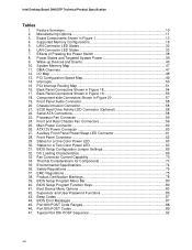
...Summary 10 1.1.2 Manufacturing Options 11 1.1.3 Board Layout 12 1.1.4 Block Diagram 14 1.2 Online Support ...15 1.3 Processor ...15 1.4 System Memory ...16 1.4.1 Memory Configurations 17 1.5 Intel® 945G Chipset ...21 1.5.1 Intel 945G Graphics Subsystem 21 1.5.2 USB ...23 1.5.3 IDE Support 24 1.5.4 Real-Time Clock, CMOS SRAM, and....1 LAN Subsystem Software 31 1.10.2 10/100 Mbits/sec LAN Subsystem 31 1.10.3 Gigabit LAN Subsystem 32 1.10.4 Intel® Active Management Technology (Optional 33 1.10.5 Alert Standard Format (ASF) Support (Optional 35 1.11 Hardware Management Subsystem...
...Summary 10 1.1.2 Manufacturing Options 11 1.1.3 Board Layout 12 1.1.4 Block Diagram 14 1.2 Online Support ...15 1.3 Processor ...15 1.4 System Memory ...16 1.4.1 Memory Configurations 17 1.5 Intel® 945G Chipset ...21 1.5.1 Intel 945G Graphics Subsystem 21 1.5.2 USB ...23 1.5.3 IDE Support 24 1.5.4 Real-Time Clock, CMOS SRAM, and....1 LAN Subsystem Software 31 1.10.2 10/100 Mbits/sec LAN Subsystem 31 1.10.3 Gigabit LAN Subsystem 32 1.10.4 Intel® Active Management Technology (Optional 33 1.10.5 Alert Standard Format (ASF) Support (Optional 35 1.11 Hardware Management Subsystem...

Product Specification
Page 7
.../Back Panel Audio Connector Options for Omni-directional Airflow 71 29. Location of the Standby Power Indicator LED 44 17. Component-side Connectors 56 21. Processor Heatsink for 6-Channel (5.1) Audio Subsystem .... 30 12. 6-Channel (5.1) Audio Subsystem Block Diagram 30 13. Block Diagram...14 3. Dual Channel (Interleaved) Mode Configuration with the 8-Channel...
.../Back Panel Audio Connector Options for Omni-directional Airflow 71 29. Location of the Standby Power Indicator LED 44 17. Component-side Connectors 56 21. Processor Heatsink for 6-Channel (5.1) Audio Subsystem .... 30 12. 6-Channel (5.1) Audio Subsystem Block Diagram 30 13. Block Diagram...14 3. Dual Channel (Interleaved) Mode Configuration with the 8-Channel...
Product Specification
Page 8
... Power Switch 38 8. Interrupts ...50 15. PCI Interrupt Routing Map 51 16. Chassis Intrusion Connector 58 21. Serial ATA Connectors 58 23. Processor Fan Connector 59 24. Intel Desktop Board D945GTP Technical Product Specification Tables 1. Manufacturing Options 11 3. Back Panel Connectors Shown in Figure 18 54 17. Auxiliary Front Panel Power/Sleep LED...
... Power Switch 38 8. Interrupts ...50 15. PCI Interrupt Routing Map 51 16. Chassis Intrusion Connector 58 21. Serial ATA Connectors 58 23. Processor Fan Connector 59 24. Intel Desktop Board D945GTP Technical Product Specification Tables 1. Manufacturing Options 11 3. Back Panel Connectors Shown in Figure 18 54 17. Auxiliary Front Panel Power/Sleep LED...


