
Product Specification
Page 5
... 1.2 Board Differences ...11 1.3 Overview ...12 1.3.1 Feature Summary 12 1.3.2 Manufacturing Options 13 1.3.3 Board Layouts 14 1.3.4 Block Diagram 18 1.4 Online Support ...19 1.5 Processor ...19 1.6 System Memory ...20 1.6.1 Memory Configurations 21 1.7 Intel® 925XE Chipset 25 1.7.1 USB ...25 1.7.2 IDE Support 25 1.7.3 Real-Time Clock, CMOS SRAM, and Battery 28 1.8 PCI Express Connectors 28 1.9 Auxiliary Power (AUX...
... 1.2 Board Differences ...11 1.3 Overview ...12 1.3.1 Feature Summary 12 1.3.2 Manufacturing Options 13 1.3.3 Board Layouts 14 1.3.4 Block Diagram 18 1.4 Online Support ...19 1.5 Processor ...19 1.6 System Memory ...20 1.6.1 Memory Configurations 21 1.7 Intel® 925XE Chipset 25 1.7.1 USB ...25 1.7.2 IDE Support 25 1.7.3 Real-Time Clock, CMOS SRAM, and Battery 28 1.8 PCI Express Connectors 28 1.9 Auxiliary Power (AUX...
Product Specification
Page 6
Intel Desktop Boards D925XECV2/D925XEBC2 Technical Product Specification 1.15 Trusted Platform Module (Optional 47 1.15.1 System Requirements 47 1.15.2 Warning of Potential Data Loss 47 1.15.3 Security... Addressable Memory 55 2.2.2 Memory Map 57 2.3 DMA Channels ...57 2.4 Fixed I/O Map...58 2.5 PCI Configuration Space Map 59 2.6 Interrupts ...60 2.7 PCI Conventional Interrupt Routing Map 61 2.8 Connectors...63 2.8.1 Back Panel Connectors 63 2.8.2 Component-side Connectors 68 2.9 Jumper Block ...80 2.10 Mechanical Considerations 81 2.10.1 D925XECV2 Form Factor 81 2.10.2 D925XEBC2 Form ...
Intel Desktop Boards D925XECV2/D925XEBC2 Technical Product Specification 1.15 Trusted Platform Module (Optional 47 1.15.1 System Requirements 47 1.15.2 Warning of Potential Data Loss 47 1.15.3 Security... Addressable Memory 55 2.2.2 Memory Map 57 2.3 DMA Channels ...57 2.4 Fixed I/O Map...58 2.5 PCI Configuration Space Map 59 2.6 Interrupts ...60 2.7 PCI Conventional Interrupt Routing Map 61 2.8 Connectors...63 2.8.1 Back Panel Connectors 63 2.8.2 Component-side Connectors 68 2.9 Jumper Block ...80 2.10 Mechanical Considerations 81 2.10.1 D925XECV2 Form Factor 81 2.10.2 D925XEBC2 Form ...

Product Specification
Page 7
... Map 56 19. Memory Channel and DIMM Configuration 21 5. Dual Channel (Interleaved) Mode Configuration with Three DIMMs 24 10. Dual Channel (Interleaved) Mode Configuration with Intel® Rapid BIOS Boot 100 3.8.1 Peripheral Selection and Configuration 100 3.8.2 Intel Rapid BIOS Boot 100 3.9 BIOS Security Features 101 4 Error Messages and Beep Codes 4.1 BIOS ... 14 2. LAN Connector LED Locations 35 15. Contents 3 Overview of the Standby Power Indicator LED on the D925XECV2 Board 46 18. Desktop Board D925XEBC2 Components 16 3. Block Diagram...18 4. Thermal Monitoring for...
... Map 56 19. Memory Channel and DIMM Configuration 21 5. Dual Channel (Interleaved) Mode Configuration with Three DIMMs 24 10. Dual Channel (Interleaved) Mode Configuration with Intel® Rapid BIOS Boot 100 3.8.1 Peripheral Selection and Configuration 100 3.8.2 Intel Rapid BIOS Boot 100 3.9 BIOS Security Features 101 4 Error Messages and Beep Codes 4.1 BIOS ... 14 2. LAN Connector LED Locations 35 15. Contents 3 Overview of the Standby Power Indicator LED on the D925XECV2 Board 46 18. Desktop Board D925XEBC2 Components 16 3. Block Diagram...18 4. Thermal Monitoring for...
Product Specification
Page 8
...ATA Connectors 73 28. Location of Board Differences 11 2. Supported Memory Configurations 20 7. PCI Configuration Space Map 59 15. Main Power Connector 75 30. Front Panel Connector 76 34. Intel Desktop Boards D925XECV2/D925XEBC2 Technical Product Specification 20. Desktop Board D925XECV2 Dimensions 81 28. ...73 29. Back Panel Connectors for a Two-Color Power LED 77 viii Desktop Board D925XEBC2 Dimensions 82 29. Back Panel Connectors Shown in Figure 2 17 6. System Memory Map 57 12. Interrupts ...60 16. Processor Fan Connector and Auxiliary Rear Fan Connector ...
...ATA Connectors 73 28. Location of Board Differences 11 2. Supported Memory Configurations 20 7. PCI Configuration Space Map 59 15. Main Power Connector 75 30. Front Panel Connector 76 34. Intel Desktop Boards D925XECV2/D925XEBC2 Technical Product Specification 20. Desktop Board D925XECV2 Dimensions 81 28. ...73 29. Back Panel Connectors for a Two-Color Power LED 77 viii Desktop Board D925XEBC2 Dimensions 82 29. Back Panel Connectors Shown in Figure 2 17 6. System Memory Map 57 12. Interrupts ...60 16. Processor Fan Connector and Auxiliary Rear Fan Connector ...
Product Specification
Page 11
... Desktop Boards used an add-in card connector referred to as PCI. Table 1. Summary of Intel Desktop Boards adds a new technology for Trusted Platform Module (TPM) D925XEBC2 • microATX Form Factor (9.60 inches by 9.60 inches [243.84 millimeters by 243....This Chapter Contains 1.1 PCI Bus Terminology Change 11 1.2 Board Differences ...11 1.3 Overview ...12 1.4 Online Support ...19 1.5 Processor ...19 1.6 System Memory ...20 1.7 Intel® 925X Chipset...25 1.8 PCI Express Connectors 28 1.9 Auxiliary Power (AUX PWR) Output Connector 28 1.10 I/O Controller...29 1.11 Audio Subsystem ...
... Desktop Boards used an add-in card connector referred to as PCI. Table 1. Summary of Intel Desktop Boards adds a new technology for Trusted Platform Module (TPM) D925XEBC2 • microATX Form Factor (9.60 inches by 9.60 inches [243.84 millimeters by 243....This Chapter Contains 1.1 PCI Bus Terminology Change 11 1.2 Board Differences ...11 1.3 Overview ...12 1.4 Online Support ...19 1.5 Processor ...19 1.6 System Memory ...20 1.7 Intel® 925X Chipset...25 1.8 PCI Express Connectors 28 1.9 Auxiliary Power (AUX PWR) Output Connector 28 1.10 I/O Controller...29 1.11 Audio Subsystem ...

Product Specification
Page 12
...84 millimeters]) • D925XEBC2: microATX (9.60 inches by 9.60 inches [243.84 millimeters by 243.84 millimeters]) Support for an Intel® Pentium® 4 processor in an LGA775 socket with a 1066, 800, or 533 MHz system bus • Four 240-pin DDR2 SDRAM Dual Inline Memory Module (DIMM) sockets... • Support for DDR2 400 MHz and DDR2 533 MHz DIMMs • Support for up to RAM support • Wake on PCI, RS-232, front panel, PS/2 devices, and USB ports continued 12 Intel Desktop Boards D925XECV2/D925XEBC2 Technical Product ...
...84 millimeters]) • D925XEBC2: microATX (9.60 inches by 9.60 inches [243.84 millimeters by 243.84 millimeters]) Support for an Intel® Pentium® 4 processor in an LGA775 socket with a 1066, 800, or 533 MHz system bus • Four 240-pin DDR2 SDRAM Dual Inline Memory Module (DIMM) sockets... • Support for DDR2 400 MHz and DDR2 533 MHz DIMMs • Support for up to RAM support • Wake on PCI, RS-232, front panel, PS/2 devices, and USB ports continued 12 Intel Desktop Boards D925XECV2/D925XEBC2 Technical Product ...
Product Specification
Page 18
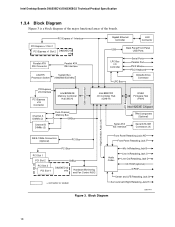
... Socket System Bus (1066/800/533 MHz) PCI Express x16 Interface PCI Express x16 Connector Intel 82925XE Memory Controller Hub (MCH) Channel A DIMMs (2) Channel B DIMMs (2) Dual-Channel Memory Bus SMBus DMI Interconnect Gigabit Ethernet Controller LAN Connector USB Back Panel/Front Panel USB Ports.../Retasking Jack D CD-ROM (optional) S/PDIF Center and LFE/Retasking Jack G Surround Left-Right/Retasking Jack H Figure 3. Intel Desktop Boards D925XECV2/D925XEBC2 Technical Product Specification 1.3.4 Block Diagram Figure 3 is a block diagram of the major functional areas of the boards.
... Socket System Bus (1066/800/533 MHz) PCI Express x16 Interface PCI Express x16 Connector Intel 82925XE Memory Controller Hub (MCH) Channel A DIMMs (2) Channel B DIMMs (2) Dual-Channel Memory Bus SMBus DMI Interconnect Gigabit Ethernet Controller LAN Connector USB Back Panel/Front Panel USB Ports.../Retasking Jack D CD-ROM (optional) S/PDIF Center and LFE/Retasking Jack G Surround Left-Right/Retasking Jack H Figure 3. Intel Desktop Boards D925XECV2/D925XEBC2 Technical Product Specification 1.3.4 Block Diagram Figure 3 is a block diagram of the major functional areas of the boards.
Product Specification
Page 20
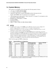
... recognize 1.9 V DIMMs (via the SPD data structure) and reconfigure the memory voltage regulator circuit for optimum performance. Intel Desktop Boards D925XECV2/D925XEBC2 Technical Product Specification 1.6 System Memory The boards have four DIMM sockets and support the following memory features: • 1.8 V and 1.9 V DDR2 SDRAM DIMMs • 3-3-3 memory timing with 1.9 V DIMMs • Unbuffered, single-sided or double-sided...
... recognize 1.9 V DIMMs (via the SPD data structure) and reconfigure the memory voltage regulator circuit for optimum performance. Intel Desktop Boards D925XECV2/D925XEBC2 Technical Product Specification 1.6 System Memory The boards have four DIMM sockets and support the following memory features: • 1.8 V and 1.9 V DDR2 SDRAM DIMMs • 3-3-3 memory timing with 1.9 V DIMMs • Unbuffered, single-sided or double-sided...

Product Specification
Page 21
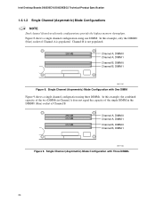
...: • Dual channel (Interleaved) mode. Dual channel mode is equivalent to the other but the installed memory capacity for additional information on available memory. 1.6.1 Memory Configurations The Intel 82925XE MCH supports two types of both channels are black. Memory Channel and DIMM Configuration 21 Technology and device width can vary from one channel to Section...
...: • Dual channel (Interleaved) mode. Dual channel mode is equivalent to the other but the installed memory capacity for additional information on available memory. 1.6.1 Memory Configurations The Intel 82925XE MCH supports two types of both channels are black. Memory Channel and DIMM Configuration 21 Technology and device width can vary from one channel to Section...
Product Specification
Page 24
...) Mode Configuration with Three DIMMs 24 Channel B is populated. Single Channel (Asymmetric) Mode Configuration with One DIMM Figure 9 shows a single channel configuration using one DIMM. Intel Desktop Boards D925XECV2/D925XEBC2 Technical Product Specification 1.6.1.2 Single Channel (Asymmetric) Mode Configurations NOTE Dual channel (Interleaved) mode configurations provide the highest...
...) Mode Configuration with Three DIMMs 24 Channel B is populated. Single Channel (Asymmetric) Mode Configuration with One DIMM Figure 9 shows a single channel configuration using one DIMM. Intel Desktop Boards D925XECV2/D925XEBC2 Technical Product Specification 1.6.1.2 Single Channel (Asymmetric) Mode Configurations NOTE Dual channel (Interleaved) mode configurations provide the highest...

Product Specification
Page 25
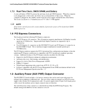
... of the front panel USB connectors on the Desktop Board D925XECV2 The location of the front panel USB connectors on the Desktop Board D925XEBC2 Refer to Figure 20, page 66 Figure 21, page 68 Figure 22, page 70 1.7.2 IDE Support The board provides five IDE...PCI Express bus, and the DMI interconnect. The Parallel ATA IDE interface supports the following devices: • Intel 82925XE Memory Controller Hub (MCH) with Direct Media Interface (DMI) interconnect • Intel 82801FR I/O Controller Hub (ICH6-R) with dual stacked back panel connectors adjacent to the audio connectors •...
... of the front panel USB connectors on the Desktop Board D925XECV2 The location of the front panel USB connectors on the Desktop Board D925XEBC2 Refer to Figure 20, page 66 Figure 21, page 68 Figure 22, page 70 1.7.2 IDE Support The board provides five IDE...PCI Express bus, and the DMI interconnect. The Parallel ATA IDE interface supports the following devices: • Intel 82925XE Memory Controller Hub (MCH) with Direct Media Interface (DMI) interconnect • Intel 82801FR I/O Controller Hub (ICH6-R) with dual stacked back panel connectors adjacent to the audio connectors •...
Product Specification
Page 28
... Express connectors: • One PCI Express x16 connector. Intel Desktop Boards D925XECV2/D925XEBC2 Technical Product Specification 1.7.3 Real-Time Clock, CMOS SRAM, and Battery A coin-cell battery (CR2032) powers the real-time clock and CMOS memory. The x1 interfaces support simultaneous transfer speeds up to 4... Gbytes/sec. • Two PCI Express x1 connectors on the D925XEBC2 board. If a power supply with 3.3 VSB applied. The default setting ...
... Express connectors: • One PCI Express x16 connector. Intel Desktop Boards D925XECV2/D925XEBC2 Technical Product Specification 1.7.3 Real-Time Clock, CMOS SRAM, and Battery A coin-cell battery (CR2032) powers the real-time clock and CMOS memory. The x1 interfaces support simultaneous transfer speeds up to 4... Gbytes/sec. • Two PCI Express x1 connectors on the D925XEBC2 board. If a power supply with 3.3 VSB applied. The default setting ...

Product Specification
Page 36
Intel Desktop Boards D925XECV2/D925XEBC2 Technical Product Specification 1.12.3 Alert...; Monitoring of system firmware progress events, including: ⎯ BIOS present ⎯ Primary processor initialization ⎯ Memory initialization ⎯ Video initialization ⎯ PCI resource configuration ⎯ Hard-disk initialization ⎯ User authentication &#... software and drivers are available from different types of system firmware error events, including: ⎯ Memory missing ⎯ Memory failure ⎯ No video device ⎯ Keyboard failure ⎯ Hard-disk failure ⎯ No...
Intel Desktop Boards D925XECV2/D925XEBC2 Technical Product Specification 1.12.3 Alert...; Monitoring of system firmware progress events, including: ⎯ BIOS present ⎯ Primary processor initialization ⎯ Memory initialization ⎯ Video initialization ⎯ PCI resource configuration ⎯ Hard-disk initialization ⎯ User authentication &#... software and drivers are available from different types of system firmware error events, including: ⎯ Memory missing ⎯ Memory failure ⎯ No video device ⎯ Keyboard failure ⎯ Hard-disk failure ⎯ No...
Product Specification
Page 55
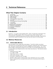
...ports (up to system address space being allocated for PCI Conventional and PCI Express add-in cards 55 Table 11 describes the system memory map, Table 12 lists the DMA channels, Table 13 shows the I /O Map...58 2.5 PCI Configuration Space Map 59 2.6...Reliability...89 2.14 Environmental ...90 2.1 Introduction Sections 2.2 - 2.6 contain several standalone tables. 2 Technical Reference What This Chapter Contains 2.1 Introduction ...55 2.2 Memory Resources ...55 2.3 DMA Channels ...57 2.4 Fixed I /O map, Table 14 defines the PCI Conventional bus configuration space map, and Table 15 describes the...
...ports (up to system address space being allocated for PCI Conventional and PCI Express add-in cards 55 Table 11 describes the system memory map, Table 12 lists the DMA channels, Table 13 shows the I /O Map...58 2.5 PCI Configuration Space Map 59 2.6...Reliability...89 2.14 Environmental ...90 2.1 Introduction Sections 2.2 - 2.6 contain several standalone tables. 2 Technical Reference What This Chapter Contains 2.1 Introduction ...55 2.2 Memory Resources ...55 2.3 DMA Channels ...57 2.4 Fixed I /O map, Table 14 defines the PCI Conventional bus configuration space map, and Table 15 describes the...
Product Specification
Page 56
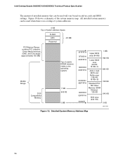
... 09FFFFH 00000H Upper BIOS area (64 KB) Lower BIOS area (64 KB; 16 KB x 4) Add-in cards and BIOS settings. Intel Desktop Boards D925XECV2/D925XEBC2 Technical Product Specification The amount of installed memory that can be used when there is no overlap of system addresses. 4 GB Top of System Address Space FLASH APIC...
... 09FFFFH 00000H Upper BIOS area (64 KB) Lower BIOS area (64 KB; 16 KB x 4) Add-in cards and BIOS settings. Intel Desktop Boards D925XECV2/D925XEBC2 Technical Product Specification The amount of installed memory that can be used when there is no overlap of system addresses. 4 GB Top of System Address Space FLASH APIC...
Product Specification
Page 57
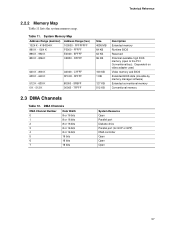
... - 800 K 639 K - 640 K 512 K - 639 K 0 K - 512 K A0000 - Dependent on video adapter used. FFFFF E0000 - Video memory and BIOS Extended BIOS data (movable by memory manager software) Extended conventional memory Conventional memory 2.3 DMA Channels Table 12. DMA Channels DMA Channel Number 0 1 2 3 4 5 6 7 Data Width 8 or 16 bits 8 or 16 bits 8...- 7FFFF Size 4095 MB 64 KB 64 KB 96 KB 160 KB 1 KB 127 KB 512 KB Description Extended memory Runtime BIOS Reserved Potential available high DOS memory (open to the PCI Conventional bus). FFFFFFFF F0000 - EFFFF C8000 - Technical Reference...
... - 800 K 639 K - 640 K 512 K - 639 K 0 K - 512 K A0000 - Dependent on video adapter used. FFFFF E0000 - Video memory and BIOS Extended BIOS data (movable by memory manager software) Extended conventional memory Conventional memory 2.3 DMA Channels Table 12. DMA Channels DMA Channel Number 0 1 2 3 4 5 6 7 Data Width 8 or 16 bits 8 or 16 bits 8...- 7FFFF Size 4095 MB 64 KB 64 KB 96 KB 160 KB 1 KB 127 KB 512 KB Description Extended memory Runtime BIOS Reserved Potential available high DOS memory (open to the PCI Conventional bus). FFFFFFFF F0000 - EFFFF C8000 - Technical Reference...
Product Specification
Page 59
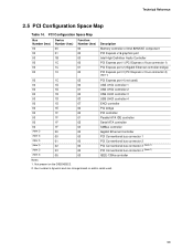
Bus number is dynamic and can change based on the D925XEBC2. 2. Technical Reference 2.5 PCI Configuration Space Map Table 14. Not present on add-in cards used ) 00 1D 00 USB UHCI controller 1 00 1D 01 USB ... 00 00 Device Number (hex) 00 01 1B 1C 1C 1C Function Number (hex) 00 00 00 00 01 02 Description Memory controller of Intel 82925XE component PCI Express x16 graphics port Intel High Definition Audio Controller PCI Express port 1 (PCI Express x1 bus connector 1) PCI Express port 2 (Gigabit Ethernet controller bridge) PCI...
Bus number is dynamic and can change based on the D925XEBC2. 2. Technical Reference 2.5 PCI Configuration Space Map Table 14. Not present on add-in cards used ) 00 1D 00 USB UHCI controller 1 00 1D 01 USB ... 00 00 Device Number (hex) 00 01 1B 1C 1C 1C Function Number (hex) 00 00 00 00 01 02 Description Memory controller of Intel 82925XE component PCI Express x16 graphics port Intel High Definition Audio Controller PCI Express port 1 (PCI Express x1 bus connector 1) PCI Express port 2 (Gigabit Ethernet controller bridge) PCI...
Product Specification
Page 85
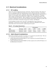
...loading characteristics of all three expansion slots and the PCI Express x16 slot filled) must not exceed 14 A. • A fully loaded Desktop Board D925XEBC2 (all active components within the board that impact its power delivery subsystems. The analysis does not include PCI add-in cards. Table 37. Maximum... board that is similar to determine the overall system power requirements. These calculations are not based on specific processor values or memory configurations but are designed to a particular processor speed. This data is based on the board that is similar to the processor...
...loading characteristics of all three expansion slots and the PCI Express x16 slot filled) must not exceed 14 A. • A fully loaded Desktop Board D925XEBC2 (all active components within the board that impact its power delivery subsystems. The analysis does not include PCI add-in cards. Table 37. Maximum... board that is similar to determine the overall system power requirements. These calculations are not based on specific processor values or memory configurations but are designed to a particular processor speed. This data is based on the board that is similar to the processor...
Product Specification
Page 95
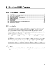
... USB Support...97 3.6 BIOS Updates ...98 3.7 Boot Options ...99 3.8 Fast Booting Systems with Intel® Rapid BIOS Boot 100 3.9 BIOS Security Features 101 3.1 Introduction The Desktop Boards D925XECV2 and D925XEBC2 use an Intel/AMI BIOS that is stored in the BIOS and reports if the two match. The BIOS Setup... The maintenance menu is displayed only when the Desktop Board is accessed by pressing the key after the Power-On Self-Test (POST) memory test begins and before the operating system boot begins. The FWH contains the BIOS Setup program, POST, the PCI auto-configuration utility, ...
... USB Support...97 3.6 BIOS Updates ...98 3.7 Boot Options ...99 3.8 Fast Booting Systems with Intel® Rapid BIOS Boot 100 3.9 BIOS Security Features 101 3.1 Introduction The Desktop Boards D925XECV2 and D925XEBC2 use an Intel/AMI BIOS that is stored in the BIOS and reports if the two match. The BIOS Setup... The maintenance menu is displayed only when the Desktop Board is accessed by pressing the key after the Power-On Self-Test (POST) memory test begins and before the operating system boot begins. The FWH contains the BIOS Setup program, POST, the PCI auto-configuration utility, ...
Product Specification
Page 96
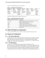
... Save the current values and exits the BIOS Setup program Exits the menu 3.2 BIOS Flash Memory Organization The Firmware Hub (FWH) includes a 8 Mbit (1024 KB) symmetrical flash memory device. 3.3 Resource Configuration 3.3.1 PCI Autoconfiguration The BIOS can automatically configure PCI devices. Any...program, the BIOS automatically sets up the PCI IDE connector with independent I /O space, and other system resources. Intel Desktop Boards D925XECV2/D925XEBC2 Technical Product Specification Table 44 lists the BIOS Setup program menu features. BIOS Setup Program Menu Bar Maintenance Main ...
... Save the current values and exits the BIOS Setup program Exits the menu 3.2 BIOS Flash Memory Organization The Firmware Hub (FWH) includes a 8 Mbit (1024 KB) symmetrical flash memory device. 3.3 Resource Configuration 3.3.1 PCI Autoconfiguration The BIOS can automatically configure PCI devices. Any...program, the BIOS automatically sets up the PCI IDE connector with independent I /O space, and other system resources. Intel Desktop Boards D925XECV2/D925XEBC2 Technical Product Specification Table 44 lists the BIOS Setup program menu features. BIOS Setup Program Menu Bar Maintenance Main ...


