
Product Specification
Page 9
...106 52. Contents 36. Fan Connector Current Capability 86 39. BIOS Setup Program Function Keys 96 46. Boot Block Recovery Code Checkpoints 105 51. Lower Nibble High Byte Functions 110 55. BIOS Error Messages 103 49. EMC Regulations ...91 43. Uncompressed INIT ...High Byte Functions 109 54. Boot Device Menu Options 99 47. Desktop Board D925XECV2/D925XEBC2 Environmental Specifications 90 41. Supervisor and User Password Functions 101 48. BIOS Setup Configuration Jumper Settings 80 37. DC Loading Characteristics 85 38. Beep Codes ...110 ix Bus Initialization...
...106 52. Contents 36. Fan Connector Current Capability 86 39. BIOS Setup Program Function Keys 96 46. Boot Block Recovery Code Checkpoints 105 51. Lower Nibble High Byte Functions 110 55. BIOS Error Messages 103 49. EMC Regulations ...91 43. Uncompressed INIT ...High Byte Functions 109 54. Boot Device Menu Options 99 47. Desktop Board D925XECV2/D925XEBC2 Environmental Specifications 90 41. Supervisor and User Password Functions 101 48. BIOS Setup Configuration Jumper Settings 80 37. DC Loading Characteristics 85 38. Beep Codes ...110 ix Bus Initialization...
Product Specification
Page 20
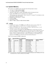
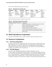
This allows the BIOS to read the SPD data and program the chipset to single-sided memory modules (containing one row of SDRAM). 20 Table 6 lists the supported DIMM configurations. Intel Desktop Boards D925XECV2/D925XEBC2 Technical Product Specification 1.6 System Memory The boards have four DIMM sockets and support ... 2.2.1 on page 55 for information on the total amount of SDRAM) and "SS" refers to accurately configure memory settings for 1.9 V, 3-3-3 memory timing operation. • Remove the PCI Express x16 video card before installing or upgrading memory to correctly configure...
This allows the BIOS to read the SPD data and program the chipset to single-sided memory modules (containing one row of SDRAM). 20 Table 6 lists the supported DIMM configurations. Intel Desktop Boards D925XECV2/D925XEBC2 Technical Product Specification 1.6 System Memory The boards have four DIMM sockets and support ... 2.2.1 on page 55 for information on the total amount of SDRAM) and "SS" refers to accurately configure memory settings for 1.9 V, 3-3-3 memory timing operation. • Remove the PCI Express x16 video card before installing or upgrading memory to correctly configure...
Product Specification
Page 26
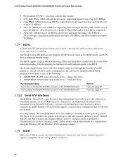
...can operate in both legacy and native modes. The Parallel ATA IDE interface also supports ATAPI devices (such as a boot device by setting the BIOS Setup program's Boot menu to 66 MB/sec. floppy disk drive) • ARMD-HDD (ATAPI removable media device - For ... channel. Native mode is used for configurations using the transfer modes. Intel Desktop Boards D925XECV2/D925XEBC2 Technical Product Specification • Programmed I /O and IRQ resources are faster timings and require a specialized cable to the BIOS. ATA-66 protocol is similar to Ultra DMA and is used ....
...can operate in both legacy and native modes. The Parallel ATA IDE interface also supports ATAPI devices (such as a boot device by setting the BIOS Setup program's Boot menu to 66 MB/sec. floppy disk drive) • ARMD-HDD (ATAPI removable media device - For ... channel. Native mode is used for configurations using the transfer modes. Intel Desktop Boards D925XECV2/D925XEBC2 Technical Product Specification • Programmed I /O and IRQ resources are faster timings and require a specialized cable to the BIOS. ATA-66 protocol is similar to Ultra DMA and is used ....

Product Specification
Page 27
... existing Serial ATA ports, correctly configuring the BIOS, and installing drivers. NOTE The SCSI Hard Drive Activity LED connector is not available on the D925XEBC2 board. For information about Serial ATA RAID configuration Refer to http://developer.intel.com/design/motherbd/cv2/index.htm 1.7.2.5 SCSI... Array of Independent Drives) level 0 and RAID level 1 on separate disk drives. Two physical drives, of identical size, maintain duplicate sets of the add-in hard drive controller to use the same LED as follows: • RAID 0 supports data striping. Two physical drives...
... existing Serial ATA ports, correctly configuring the BIOS, and installing drivers. NOTE The SCSI Hard Drive Activity LED connector is not available on the D925XEBC2 board. For information about Serial ATA RAID configuration Refer to http://developer.intel.com/design/motherbd/cv2/index.htm 1.7.2.5 SCSI... Array of Independent Drives) level 0 and RAID level 1 on separate disk drives. Two physical drives, of identical size, maintain duplicate sets of the add-in hard drive controller to use the same LED as follows: • RAID 0 supports data striping. Two physical drives...
Product Specification
Page 28
...duplex) transfer speeds up to 4 Gbytes/sec. • Two PCI Express x1 connectors on the D925XEBC2 board. The default setting in the BIOS is compatible with PCI Conventional compliant operating systems. Additional features of the PCI Express interface includes the following... PCI Express connectors: • One PCI Express x16 connector. one PCI Express x1 connector on the D925XECV2 board; Intel Desktop Boards D925XECV2/D925XEBC2...
...duplex) transfer speeds up to 4 Gbytes/sec. • Two PCI Express x1 connectors on the D925XEBC2 board. The default setting in the BIOS is compatible with PCI Conventional compliant operating systems. Additional features of the PCI Express interface includes the following... PCI Express connectors: • One PCI Express x16 connector. one PCI Express x1 connector on the D925XECV2 board; Intel Desktop Boards D925XECV2/D925XEBC2...
Product Specification
Page 29
... Table 28, page 73 NOTE The auxiliary power output connector is not present on the D925XEBC2 board. 1.10 I/O Controller The I /O controller. 1.10.1 Serial Port The boards ... a programmable wake-up event interface • PCI Conventional bus power management support The BIOS Setup program provides configuration options for storage devices. • Do not connect any devices...to this connector. For information about The location of the serial port A connector Refer to set the parallel port mode. The connector circuitry includes overcurrent protection components that draw more than ...
... Table 28, page 73 NOTE The auxiliary power output connector is not present on the D925XEBC2 board. 1.10 I/O Controller The I /O controller. 1.10.1 Serial Port The boards ... a programmable wake-up event interface • PCI Conventional bus power management support The BIOS Setup program provides configuration options for storage devices. • Do not connect any devices...to this connector. For information about The location of the serial port A connector Refer to set the parallel port mode. The connector circuitry includes overcurrent protection components that draw more than ...

Product Specification
Page 43
Setting this state S1, S3, S4, S5 (Note) S1, S3 S1, S3, S4, S5 (Note) S1,...Serial Port A) PME# signal Power switch PS/2 devices RTC alarm USB WAKE# ...from specific states. The Desktop Boards D925XECV2 and D925XEBC2 provide several power management hardware features, including: • Power connector • Fan connectors • LAN wake capabilities • ... PS/2 keyboard • PME# signal wake-up support • WAKE# signal wake-up events from LAN in the BIOS Setup program. Failure to Power On will enable a wake-up event from an ACPI state requires an operating system that...
Setting this state S1, S3, S4, S5 (Note) S1, S3 S1, S3, S4, S5 (Note) S1,...Serial Port A) PME# signal Power switch PS/2 devices RTC alarm USB WAKE# ...from specific states. The Desktop Boards D925XECV2 and D925XEBC2 provide several power management hardware features, including: • Power connector • Fan connectors • LAN wake capabilities • ... PS/2 keyboard • PME# signal wake-up support • WAKE# signal wake-up events from LAN in the BIOS Setup program. Failure to Power On will enable a wake-up event from an ACPI state requires an operating system that...
Product Specification
Page 44
...Connector ATX12V-compliant power supplies can be capable of the computer through system control. Intel Desktop Boards D925XECV2/D925XEBC2 Technical Product Specification Resume on Ring enables telephony devices to access the computer when ...wake-up the computer. 44 The computer's response can turn off or in the BIOS Setup program's Boot menu. For information about The location of the fan connectors The... Capabilities CAUTION For LAN wake capabilities, the +5 V standby line for the power supply must be set using the Last Power State feature in the S3, S4, or S5 state. • Each ...
...Connector ATX12V-compliant power supplies can be capable of the computer through system control. Intel Desktop Boards D925XECV2/D925XEBC2 Technical Product Specification Resume on Ring enables telephony devices to access the computer when ...wake-up the computer. 44 The computer's response can turn off or in the BIOS Setup program's Boot menu. For information about The location of the fan connectors The... Capabilities CAUTION For LAN wake capabilities, the +5 V standby line for the power supply must be set using the Last Power State feature in the S3, S4, or S5 state. • Each ...
Product Specification
Page 52
...1. Some circuitry on the board to transfer ownership of all steps, you should automatically enter BIOS setup. 5. System should be cleared to pins 2-3. 3. Power off . Start User Initialization...Keys. 10. Failure to do this can continue to restore the security platform settings. 6. The TPM may allow the migratable keys to be recovered and might ...If you connect or disconnect cables, or install or remove any board components. Intel Desktop Boards D925XECV2/D925XEBC2 Technical Product Specification 4. To restore access to select Clear Trusted Platform Module, press ...
...1. Some circuitry on the board to transfer ownership of all steps, you should automatically enter BIOS setup. 5. System should be cleared to pins 2-3. 3. Power off . Start User Initialization...Keys. 10. Failure to do this can continue to restore the security platform settings. 6. The TPM may allow the migratable keys to be recovered and might ...If you connect or disconnect cables, or install or remove any board components. Intel Desktop Boards D925XECV2/D925XEBC2 Technical Product Specification 4. To restore access to select Clear Trusted Platform Module, press ...
Product Specification
Page 56
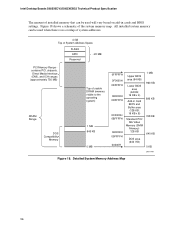
... visible to the operating system) 1 MB 640 KB 0 MB 0FFFFFH 0F0000H 0EFFFFH 0E0000H 0DFFFFH 0C0000H 0BFFFFH 0A0000H 09FFFFH 00000H Upper BIOS area (64 KB) Lower BIOS area (64 KB; 16 KB x 4) Add-in cards and BIOS settings. All installed system memory can be used will vary based on add-in Card... BIOS and Buffer area (128 KB; 16 KB x 8) Standard PCI/ ISA Video Memory (SMM Memory) 128 KB DOS area (640 KB) 1 MB 960 KB 896 KB 768 KB 640 KB 0 KB OM17140 Figure 18. Intel Desktop Boards D925XECV2/D925XEBC2...
... visible to the operating system) 1 MB 640 KB 0 MB 0FFFFFH 0F0000H 0EFFFFH 0E0000H 0DFFFFH 0C0000H 0BFFFFH 0A0000H 09FFFFH 00000H Upper BIOS area (64 KB) Lower BIOS area (64 KB; 16 KB x 4) Add-in cards and BIOS settings. All installed system memory can be used will vary based on add-in Card... BIOS and Buffer area (128 KB; 16 KB x 8) Standard PCI/ ISA Video Memory (SMM Memory) 128 KB DOS area (640 KB) 1 MB 960 KB 896 KB 768 KB 640 KB 0 KB OM17140 Figure 18. Intel Desktop Boards D925XECV2/D925XEBC2...

Product Specification
Page 80
... 3 recovery diskette is displayed. When the jumper is set to recover the BIOS configuration. Recovery None 1 The BIOS attempts to configure mode and the computer is poweredup, the BIOS compares the processor version and the microcode version in the BIOS and reports if the two match. 1 3 J6J3 .... Always turn off the power and unplug the power cord from the computer before changing a jumper setting. Otherwise, the board could be damaged. Intel Desktop Boards D925XECV2/D925XEBC2 Technical Product Specification 2.9 Jumper Block CAUTION Do not move the jumper with the power on.
... 3 recovery diskette is displayed. When the jumper is set to recover the BIOS configuration. Recovery None 1 The BIOS attempts to configure mode and the computer is poweredup, the BIOS compares the processor version and the microcode version in the BIOS and reports if the two match. 1 3 J6J3 .... Always turn off the power and unplug the power cord from the computer before changing a jumper setting. Otherwise, the board could be damaged. Intel Desktop Boards D925XECV2/D925XEBC2 Technical Product Specification 2.9 Jumper Block CAUTION Do not move the jumper with the power on.
Product Specification
Page 95
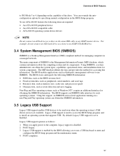
... with Intel® Rapid BIOS Boot 100 3.9 BIOS Security Features 101 3.1 Introduction The Desktop Boards D925XECV2 and D925XEBC2 use an Intel/AMI BIOS that is stored in the Firmware Hub (FWH) and can be updated using a disk-based program. The BIOS Setup program can be used to view and change the BIOS settings for the computer. When the BIOS Setup...
... with Intel® Rapid BIOS Boot 100 3.9 BIOS Security Features 101 3.1 Introduction The Desktop Boards D925XECV2 and D925XEBC2 use an Intel/AMI BIOS that is stored in the Firmware Hub (FWH) and can be updated using a disk-based program. The BIOS Setup program can be used to view and change the BIOS settings for the computer. When the BIOS Setup...
Product Specification
Page 96
... devices, including CD-ROM drives, tape drives, and Ultra DMA drives. Intel Desktop Boards D925XECV2/D925XEBC2 Technical Product Specification Table 44 lists the BIOS Setup program menu features. Table 44. BIOS Setup Program Menu Bar Maintenance Main Advanced Security Clears passwords and displays processor ... changes to configure the system. The IDE interface supports hard drives up to be onboard or add-in the BIOS Setup program, the BIOS automatically sets up or down) Selects a field (Not implemented) Executes command or selects the submenu Load the default configuration ...
... devices, including CD-ROM drives, tape drives, and Ultra DMA drives. Intel Desktop Boards D925XECV2/D925XEBC2 Technical Product Specification Table 44 lists the BIOS Setup program menu features. Table 44. BIOS Setup Program Menu Bar Maintenance Main Advanced Security Clears passwords and displays processor ... changes to configure the system. The IDE interface supports hard drives up to be onboard or add-in the BIOS Setup program, the BIOS automatically sets up or down) Selects a field (Not implemented) Executes command or selects the submenu Load the default configuration ...
Product Specification
Page 97
... and Play operating system can obtain the system types, capabilities, operational status, and installation dates for such operating systems. Using this information. The BIOS supports an SMBIOS table interface for system components. Using SMBIOS, a system administrator can obtain the SMBIOS information. 3.5 Legacy USB Support Legacy USB... NOTE Do not connect an ATA device as a slave on the capability of the drive. Legacy USB support is set to Enabled. POST completes. 97 Overview of BIOS Features to PIO Mode 3 or 4, depending on the same IDE cable as an ATAPI master device.
... and Play operating system can obtain the system types, capabilities, operational status, and installation dates for such operating systems. Using this information. The BIOS supports an SMBIOS table interface for system components. Using SMBIOS, a system administrator can obtain the SMBIOS information. 3.5 Legacy USB Support Legacy USB... NOTE Do not connect an ATA device as a slave on the capability of the drive. Legacy USB support is set to Enabled. POST completes. 97 Overview of BIOS Features to PIO Mode 3 or 4, depending on the same IDE cable as an ATAPI master device.

Product Specification
Page 98
...set to Enabled and follow the operating system's installation instructions. 3.6 BIOS Updates The BIOS can be updated from a file on a hard disk, a 1.44 MB diskette, or a CD-ROM, or from Intel can be used to configure the operating system. (Keyboards and mice are available in US English. Intel Desktop Boards D925XECV2/D925XEBC2... Technical Product Specification 5. While the operating system is no longer used to Section 1.4, page 19 3.6.1 Language Support The BIOS Setup program and help messages...
...set to Enabled and follow the operating system's installation instructions. 3.6 BIOS Updates The BIOS can be updated from a file on a hard disk, a 1.44 MB diskette, or a CD-ROM, or from Intel can be used to configure the operating system. (Keyboards and mice are available in US English. Intel Desktop Boards D925XECV2/D925XEBC2... Technical Product Specification 5. While the operating system is no longer used to Section 1.4, page 19 3.6.1 Language Support The BIOS Setup program and help messages...

Product Specification
Page 99
... • Keyboard • Mouse 3.7.4 Changing the Default Boot Device During POST Pressing the key during POST causes a boot device menu to be set in the CD-ROM drive, the system will attempt to the El Torito bootable CD-ROM format specification. Overview of available boot devices (as a... boot device. The fourth device is disabled. 3.7.1 CD-ROM Boot Booting from CD-ROM is not a bootable CD in the BIOS setup program's Boot Device Priority Submenu). Boot Device Menu Options Boot Device Menu Function Keys or Description Selects a default boot device Exits the menu...
... • Keyboard • Mouse 3.7.4 Changing the Default Boot Device During POST Pressing the key during POST causes a boot device menu to be set in the CD-ROM drive, the system will attempt to the El Torito bootable CD-ROM format specification. Overview of available boot devices (as a... boot device. The fourth device is disabled. 3.7.1 CD-ROM Boot Booting from CD-ROM is not a bootable CD in the BIOS setup program's Boot Device Priority Submenu). Boot Device Menu Options Boot Device Menu Function Keys or Description Selects a default boot device Exits the menu...
Product Specification
Page 100
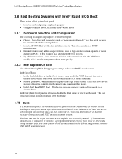
... the first boot device. Intel Desktop Boards D925XECV2/D925XEBC2 Technical Product Specification 3.8 Fast Booting Systems with Intel® Rapid BIOS Boot These factors affect system boot speed: • Selecting and configuring peripherals properly • Using an optimized BIOS, such as the Intel® Rapid BIOS 3.8.1 Peripheral Selection and Configuration The following BIOS Setup program settings reduces the POST execution...
... the first boot device. Intel Desktop Boards D925XECV2/D925XEBC2 Technical Product Specification 3.8 Fast Booting Systems with Intel® Rapid BIOS Boot These factors affect system boot speed: • Selecting and configuring peripherals properly • Using an optimized BIOS, such as the Intel® Rapid BIOS 3.8.1 Peripheral Selection and Configuration The following BIOS Setup program settings reduces the POST execution...
Product Specification
Page 101
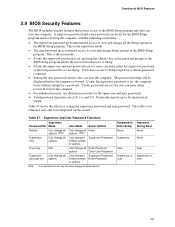
... password and a user password can change Setup options in length. This is the user mode. • If only the supervisor password is set for the BIOS Setup program and for the supervisor and user passwords. • Valid password characters are A-Z, a-z, and 0-9. If only the supervisor password is...Enter Password options Clear User Password Can change a Supervisor Password limited number Enter Password of the BIOS Setup program allows the user restricted access to Setup. • If both passwords are set , the user can enter either the supervisor password or the user password to the...
... password and a user password can change Setup options in length. This is the user mode. • If only the supervisor password is set for the BIOS Setup program and for the supervisor and user passwords. • Valid password characters are A-Z, a-z, and 0-9. If only the supervisor password is...Enter Password options Clear User Password Can change a Supervisor Password limited number Enter Password of the BIOS Setup program allows the user restricted access to Setup. • If both passwords are set , the user can enter either the supervisor password or the user password to the...

Product Specification
Page 103
...battery may be bad. Error occurred trying to set correct values. 4 Error Messages and Beep Codes What This Chapter Contains 4.1 BIOS Error Messages 103 4.2 Port 80h POST Codes 105 4.3 Bus Initialization Checkpoints 109 4.4 Speaker ...110 4.5 BIOS Beep Codes...110 4.1 BIOS Error Messages Table 48 lists the error messages and...Explanation An error occurred with Gate A20 when switching to see if it is incorrect. Could not read /write test of each. BIOS Error Messages Error Message GA20 Error Pri Master HDD Error Pri Slave HDD Error Pri Master Drive - An error occurred when testing...
...battery may be bad. Error occurred trying to set correct values. 4 Error Messages and Beep Codes What This Chapter Contains 4.1 BIOS Error Messages 103 4.2 Port 80h POST Codes 105 4.3 Bus Initialization Checkpoints 109 4.4 Speaker ...110 4.5 BIOS Beep Codes...110 4.1 BIOS Error Messages Table 48 lists the error messages and...Explanation An error occurred with Gate A20 when switching to see if it is incorrect. Could not read /write test of each. BIOS Error Messages Error Message GA20 Error Pri Master HDD Error Pri Slave HDD Error Pri Master Drive - An error occurred when testing...
English Manual Product Guide
Page 21
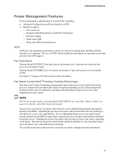
...ACPI with the desktop board requires an operating system that processor fan speed control remain enabled (default BIOS setting) when using the processor fan heat-sink included with Intel boxed processors. The chassis fan speed control feature should be disabled if a self-controlled chassis ... ⎯ Fan connectors ⎯ Suspend to RAM (Instantly Available PC technology) ⎯ Resume on Desktop Board D925XECV2 are controlled. Desktop Board D925XEBC2 has two chassis fan headers (3-pin) and one processor fan header (4-pin). NOTE Not all chassis fan headers on Ring ⎯ Wake from...
...ACPI with the desktop board requires an operating system that processor fan speed control remain enabled (default BIOS setting) when using the processor fan heat-sink included with Intel boxed processors. The chassis fan speed control feature should be disabled if a self-controlled chassis ... ⎯ Fan connectors ⎯ Suspend to RAM (Instantly Available PC technology) ⎯ Resume on Desktop Board D925XECV2 are controlled. Desktop Board D925XEBC2 has two chassis fan headers (3-pin) and one processor fan header (4-pin). NOTE Not all chassis fan headers on Ring ⎯ Wake from...


