

Product Specification
Page 2
... referenced in this specification will be obtained from future changes to only standard Intel® Desktop Boards D925XECV2 and D925XEBC2 with BIOS identifier CV92510A.86A. Current characterized errata are registered trademarks of Intel Corporation or its subsidiaries in the Intel Desktop Boards D925XECV2/D925XEBC2 Specification Update before placing your distributor to specifications and product descriptions at...
... referenced in this specification will be obtained from future changes to only standard Intel® Desktop Boards D925XECV2 and D925XEBC2 with BIOS identifier CV92510A.86A. Current characterized errata are registered trademarks of Intel Corporation or its subsidiaries in the Intel Desktop Boards D925XECV2/D925XEBC2 Specification Update before placing your distributor to specifications and product descriptions at...
Product Specification
Page 3
...available manufacturing options. It is intended to provide detailed, technical information about the conventions used in all of these Intel® Desktop Boards: D925XECV2 and D925XEBC2. Not all specifications of this level of information. Notes, Cautions, and Warnings NOTE Notes call attention to ...integrators. CAUTION Cautions are used on the Desktop Boards D925XECV2 and D925XEBC2 A map of the resources of the Desktop Boards The features supported by the BIOS Setup program A description of the BIOS error messages, beep codes, and POST codes Typographical Conventions This section...
...available manufacturing options. It is intended to provide detailed, technical information about the conventions used in all of these Intel® Desktop Boards: D925XECV2 and D925XEBC2. Not all specifications of this level of information. Notes, Cautions, and Warnings NOTE Notes call attention to ...integrators. CAUTION Cautions are used on the Desktop Boards D925XECV2 and D925XEBC2 A map of the resources of the Desktop Boards The features supported by the BIOS Setup program A description of the BIOS error messages, beep codes, and POST codes Typographical Conventions This section...

Product Specification
Page 7
... Indicator LED on the D925XECV2 Board 46 18. Desktop Board D925XEBC2 Components 16 3. Block Diagram...18 4. Dual Channel (Interleaved) Mode Configuration with Intel® Rapid BIOS Boot 100 3.8.1 Peripheral Selection and Configuration 100 3.8.2 Intel Rapid BIOS Boot 100 3.9 BIOS Security Features 101 4 Error Messages and Beep Codes 4.1 BIOS Error Messages 103 4.2 Port 80h POST Codes 105 4.3 Bus...
... Indicator LED on the D925XECV2 Board 46 18. Desktop Board D925XEBC2 Components 16 3. Block Diagram...18 4. Dual Channel (Interleaved) Mode Configuration with Intel® Rapid BIOS Boot 100 3.8.1 Peripheral Selection and Configuration 100 3.8.2 Intel Rapid BIOS Boot 100 3.9 BIOS Security Features 101 4 Error Messages and Beep Codes 4.1 BIOS Error Messages 103 4.2 Port 80h POST Codes 105 4.3 Bus...
Product Specification
Page 9
... 89 40. Uncompressed INIT Code Checkpoints 105 50. Upper Nibble High Byte Functions 109 54. EMC Regulations ...91 43. BIOS Setup Program Function Keys 96 46. Lower Nibble High Byte Functions 110 55. Product Certification Markings 94 44. Boot Block ...BIOS Setup Program Menu Bar 96 45. Runtime Code Uncompressed in F000 Shadow RAM 106 52. BIOS Error Messages 103 49. Fan Connector Current Capability 86 39. Safety Regulations ...91 42. Bus Initialization Checkpoints 109 53. Supervisor and User Password Functions 101 48. Desktop Board D925XECV2/D925XEBC2...
... 89 40. Uncompressed INIT Code Checkpoints 105 50. Upper Nibble High Byte Functions 109 54. EMC Regulations ...91 43. BIOS Setup Program Function Keys 96 46. Lower Nibble High Byte Functions 110 55. Product Certification Markings 94 44. Boot Block ...BIOS Setup Program Menu Bar 96 45. Runtime Code Uncompressed in F000 Shadow RAM 106 52. BIOS Error Messages 103 49. Fan Connector Current Capability 86 39. Safety Regulations ...91 42. Bus Initialization Checkpoints 109 53. Supervisor and User Password Functions 101 48. Desktop Board D925XECV2/D925XEBC2...

Product Specification
Page 12
...BIOS Instantly Available PC Technology Support for USB 2.0 devices • Eight USB ports • One serial port • One parallel port • Four Serial ATA interfaces • One Parallel ATA IDE interface with 3-3-3 memory timing Chipset Video Audio Intel® 925XE Chipset, consisting of the Desktop Boards D925XECV2 and D925XEBC2...with UDMA 33, ATA-66/100 support • One diskette drive interface • PS/2* keyboard and mouse ports • Intel/AMI BIOS (resident in the 8 Mbit FWH) • Support for Advanced Configuration and Power Interface (ACPI), Plug and Play, and ...
...BIOS Instantly Available PC Technology Support for USB 2.0 devices • Eight USB ports • One serial port • One parallel port • Four Serial ATA interfaces • One Parallel ATA IDE interface with 3-3-3 memory timing Chipset Video Audio Intel® 925XE Chipset, consisting of the Desktop Boards D925XECV2 and D925XEBC2...with UDMA 33, ATA-66/100 support • One diskette drive interface • PS/2* keyboard and mouse ports • Intel/AMI BIOS (resident in the 8 Mbit FWH) • Support for Advanced Configuration and Power Interface (ACPI), Plug and Play, and ...

Product Specification
Page 15
... sockets DIMM Channel B sockets I/O controller Power connector Diskette drive connector Parallel ATE IDE connector Battery Chassis intrusion connector BIOS Setup configuration jumper block 8 Mbit Firmware Hub (FWH) Front chassis fan connector Serial ATA connectors Auxiliary front panel power... LED (optional) Auxiliary power output connector (optional) Front panel USB connector TPM component (optional) Front panel USB connector Intel 82801FR I/O Controller Hub (ICH6-R) Front panel IEEE-1394a connectors (optional) IEEE-1394a controller (optional) Speaker PCI Conventional bus add-in...
... sockets DIMM Channel B sockets I/O controller Power connector Diskette drive connector Parallel ATE IDE connector Battery Chassis intrusion connector BIOS Setup configuration jumper block 8 Mbit Firmware Hub (FWH) Front chassis fan connector Serial ATA connectors Auxiliary front panel power... LED (optional) Auxiliary power output connector (optional) Front panel USB connector TPM component (optional) Front panel USB connector Intel 82801FR I/O Controller Hub (ICH6-R) Front panel IEEE-1394a connectors (optional) IEEE-1394a controller (optional) Speaker PCI Conventional bus add-in...

Product Specification
Page 17
D925XEBC2 Components Shown in Figure 2 Item/callout from Figure 2 A B C D E F G H I J K L M N O P Q R S T U V W X ... sockets I/O controller Power connector Diskette drive connector Parallel ATE IDE connector Battery Chassis intrusion connector BIOS Setup configuration jumper block 8 Mbit Firmware Hub (FWH) Front chassis fan connector Serial ATA ...connectors Auxiliary front panel power LED connector Front panel connector Front panel USB connector Front panel USB connector Intel 82801FR I/O Controller Hub (ICH6-R) Front panel IEEE-1394a connectors (optional) IEEE-1394a controller (optional) ...
D925XEBC2 Components Shown in Figure 2 Item/callout from Figure 2 A B C D E F G H I J K L M N O P Q R S T U V W X ... sockets I/O controller Power connector Diskette drive connector Parallel ATE IDE connector Battery Chassis intrusion connector BIOS Setup configuration jumper block 8 Mbit Firmware Hub (FWH) Front chassis fan connector Serial ATA ...connectors Auxiliary front panel power LED connector Front panel connector Front panel USB connector Front panel USB connector Intel 82801FR I/O Controller Hub (ICH6-R) Front panel IEEE-1394a connectors (optional) IEEE-1394a controller (optional) ...
Product Specification
Page 20
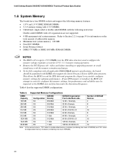
Table 6. Intel Desktop Boards D925XECV2/D925XEBC2 Technical Product Specification 1.6 System Memory The boards have four DIMM sockets and support the following memory features: • 1.8 V and 1.9 V DDR2 SDRAM DIMMs • 3-3-3 memory ... DIMMS with DIMMs that support the Serial Presence Detect (SPD) data structure. Table 6 lists the supported DIMM configurations. If non-SPD memory is installed, the BIOS will recognize 1.9 V DIMMs (via the SPD data structure) and reconfigure the memory voltage regulator circuit for 1.9 V, 3-3-3 memory timing operation. • Remove the PCI ...
Table 6. Intel Desktop Boards D925XECV2/D925XEBC2 Technical Product Specification 1.6 System Memory The boards have four DIMM sockets and support the following memory features: • 1.8 V and 1.9 V DDR2 SDRAM DIMMs • 3-3-3 memory ... DIMMS with DIMMs that support the Serial Presence Detect (SPD) data structure. Table 6 lists the supported DIMM configurations. If non-SPD memory is installed, the BIOS will recognize 1.9 V DIMMs (via the SPD data structure) and reconfigure the memory voltage regulator circuit for 1.9 V, 3-3-3 memory timing operation. • Remove the PCI ...

Product Specification
Page 25
... supports UHCI and EHCI, and uses UHCI- The Parallel ATA IDE interface supports the following devices: • Intel 82925XE Memory Controller Hub (MCH) with DMI interconnect • Firmware Hub (FWH) The MCH is attached to... D925XECV2 The location of the front panel USB connectors on the Desktop Board D925XEBC2 Refer to the cable. The ICH6-R provides the USB controller for full-speed devices. The... FWH provides the nonvolatile storage of the BIOS. Use shielded cable that have an unshielded cable attached to a USB port may not meet...
... supports UHCI and EHCI, and uses UHCI- The Parallel ATA IDE interface supports the following devices: • Intel 82925XE Memory Controller Hub (MCH) with DMI interconnect • Firmware Hub (FWH) The MCH is attached to... D925XECV2 The location of the front panel USB connectors on the Desktop Board D925XEBC2 Refer to the cable. The ICH6-R provides the USB controller for full-speed devices. The... FWH provides the nonvolatile storage of the BIOS. Use shielded cable that have an unshielded cable attached to a USB port may not meet...
Product Specification
Page 26
...the Parallel ATA IDE connector on IDE bus supporting host and target throttling and transfer rates of four Serial ATA devices. Intel Desktop Boards D925XECV2/D925XEBC2 Technical Product Specification • Programmed I /O and IRQ resources are faster timings and require a specialized cable to reduce ...low-voltage power connectors. 26 The ICH6-R's ATA-100 logic can be installed on IDE bus allows host and target throttling. The BIOS supports Logical Block Addressing (LBA) and Extended Cylinder Head Sector (ECHS) translation modes. A point-to device connections, unlike Parallel...
...the Parallel ATA IDE connector on IDE bus supporting host and target throttling and transfer rates of four Serial ATA devices. Intel Desktop Boards D925XECV2/D925XEBC2 Technical Product Specification • Programmed I /O and IRQ resources are faster timings and require a specialized cable to reduce ...low-voltage power connectors. 26 The ICH6-R's ATA-100 logic can be installed on IDE bus allows host and target throttling. The BIOS supports Logical Block Addressing (LBA) and Extended Cylinder Head Sector (ECHS) translation modes. A point-to device connections, unlike Parallel...

Product Specification
Page 27
... array. 5. Install the IAA Companion Utility (this connector should be created by using the Intel Application Accelerator (IAA) utility. 3. Level 1 provides the highest data reliability because two complete...8226; RAID 1 supports data mirroring. For proper operation, this step is not available on the D925XEBC2 board. Enable RAID Support in hard drive controller or the onboard IDE controller (Parallel ATA or Serial...board The signal names of all information are required to , either the add-in BIOS. 2. Two physical drives, of identical size, maintain duplicate sets of the SCSI...
... array. 5. Install the IAA Companion Utility (this connector should be created by using the Intel Application Accelerator (IAA) utility. 3. Level 1 provides the highest data reliability because two complete...8226; RAID 1 supports data mirroring. For proper operation, this step is not available on the D925XEBC2 board. Enable RAID Support in hard drive controller or the onboard IDE controller (Parallel ATA or Serial...board The signal names of all information are required to , either the add-in BIOS. 2. Two physical drives, of identical size, maintain duplicate sets of the SCSI...
Product Specification
Page 28
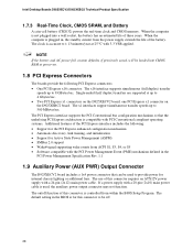
The clock is controlled from within the BIOS Setup Program. The x16 interface supports simultaneous (full duplex) transfer speeds up to 8 GBytes/sec. The on . 1.8 PCI Express Connectors The boards provide the following : &#... Power (AUX PWR) Output Connector The D925XECV2 board includes a 1x4 power connector that can be used , the auxiliary power output connector may not function. Intel Desktop Boards D925XECV2/D925XEBC2 Technical Product Specification 1.7.3 Real-Time Clock, CMOS SRAM, and Battery A coin-cell battery (CR2032) powers the real-time clock and CMOS memory. When...
The clock is controlled from within the BIOS Setup Program. The x16 interface supports simultaneous (full duplex) transfer speeds up to 8 GBytes/sec. The on . 1.8 PCI Express Connectors The boards provide the following : &#... Power (AUX PWR) Output Connector The D925XECV2 board includes a 1x4 power connector that can be used , the auxiliary power output connector may not function. Intel Desktop Boards D925XECV2/D925XEBC2 Technical Product Specification 1.7.3 Real-Time Clock, CMOS SRAM, and Battery A coin-cell battery (CR2032) powers the real-time clock and CMOS memory. When...
Product Specification
Page 29
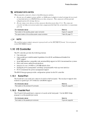
...back panel. The serial port supports data transfers at speeds up event interface • PCI Conventional bus power management support The BIOS Setup program provides configuration options for storage devices. • Do not connect any devices to this connector. For information about ... support for PCI Conventional bus systems • PS/2-style mouse and keyboard interfaces • Interface for one serial port connector located on the D925XEBC2 board. 1.10 I/O Controller The I/O controller provides the following precautions: • Do not use a Y-adapter, power splitter, or SATA ...
...back panel. The serial port supports data transfers at speeds up event interface • PCI Conventional bus power management support The BIOS Setup program provides configuration options for storage devices. • Do not connect any devices to this connector. For information about ... support for PCI Conventional bus systems • PS/2-style mouse and keyboard interfaces • Interface for one serial port connector located on the D925XEBC2 board. 1.10 I/O Controller The I/O controller provides the following precautions: • Do not use a Y-adapter, power splitter, or SATA ...
Product Specification
Page 30
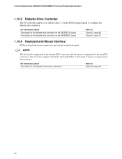
Intel Desktop Boards D925XECV2/D925XEBC2 Technical Product Specification 1.10.3 Diskette Drive Controller The I/O controller supports one diskette drive. NOTE The keyboard is supported in the bottom PS/2 connector and the mouse is connected or disconnected. Use the BIOS Setup program to Figure 21, page 68 Figure 22, page 70 1.10.4 Keyboard and Mouse Interface... supported in the top PS/2 connector. Power to Figure 20, page 66 30 For information about The location of the diskette drive connector on the D925XEBC2 board Refer to configure the diskette drive interface.
Intel Desktop Boards D925XECV2/D925XEBC2 Technical Product Specification 1.10.3 Diskette Drive Controller The I/O controller supports one diskette drive. NOTE The keyboard is supported in the bottom PS/2 connector and the mouse is connected or disconnected. Use the BIOS Setup program to Figure 21, page 68 Figure 22, page 70 1.10.4 Keyboard and Mouse Interface... supported in the top PS/2 connector. Power to Figure 20, page 66 30 For information about The location of the diskette drive connector on the D925XEBC2 board Refer to configure the diskette drive interface.

Product Specification
Page 36
...failure ⎯ Hard-disk failure ⎯ No boot media • Boot options to Section 1.4, page 19 36 Intel Desktop Boards D925XECV2/D925XEBC2 Technical Product Specification 1.12.3 Alert Standard Format (ASF) Support The boards provide the following ASF support for the onboard...bus add-in LAN cards installed in PCI Conventional bus slot 2: • Monitoring of system firmware progress events, including: ⎯ BIOS present ⎯ Primary processor initialization ⎯ Memory initialization ⎯ Video initialization ⎯ PCI resource configuration ⎯ Hard-disk initialization...
...failure ⎯ Hard-disk failure ⎯ No boot media • Boot options to Section 1.4, page 19 36 Intel Desktop Boards D925XECV2/D925XEBC2 Technical Product Specification 1.12.3 Alert Standard Format (ASF) Support The boards provide the following ASF support for the onboard...bus add-in LAN cards installed in PCI Conventional bus slot 2: • Monitoring of system firmware progress events, including: ⎯ BIOS present ⎯ Primary processor initialization ⎯ Memory initialization ⎯ Video initialization ⎯ PCI resource configuration ⎯ Hard-disk initialization...

Product Specification
Page 43
...signal Power switch PS/2 devices RTC alarm USB WAKE# ...from this option to do so can wake up event from LAN in the BIOS Setup program. NOTE The use of standby current required depends on Ring • Wake from USB • Wake from PS/2 keyboard &#... and peripherals must fully support ACPI wake events. 1.14.2 Hardware Support CAUTION Ensure that provides full ACPI support. The Desktop Boards D925XECV2 and D925XEBC2 provide several power management hardware features, including: • Power connector • Fan connectors • LAN wake capabilities • Instantly Available PC...
...signal Power switch PS/2 devices RTC alarm USB WAKE# ...from this option to do so can wake up event from LAN in the BIOS Setup program. NOTE The use of standby current required depends on Ring • Wake from USB • Wake from PS/2 keyboard &#... and peripherals must fully support ACPI wake events. 1.14.2 Hardware Support CAUTION Ensure that provides full ACPI support. The Desktop Boards D925XECV2 and D925XEBC2 provide several power management hardware features, including: • Power connector • Fan connectors • LAN wake capabilities • Instantly Available PC...
Product Specification
Page 44
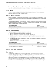
Intel Desktop Boards D925XECV2/D925XEBC2 Technical Product Specification Resume on or off). NOTE The use of the computer through system control. Failure to Figure 21, page 68 Figure 15, page ... Wake Capabilities CAUTION For LAN wake capabilities, the +5 V standby line for the power supply must be set using the Last Power State feature in the BIOS Setup program's Boot menu. The computer's response can adjust the fan speed or switch the fan on the type of providing adequate +5 V standby current. LAN...
Intel Desktop Boards D925XECV2/D925XEBC2 Technical Product Specification Resume on or off). NOTE The use of the computer through system control. Failure to Figure 21, page 68 Figure 15, page ... Wake Capabilities CAUTION For LAN wake capabilities, the +5 V standby line for the power supply must be set using the Last Power State feature in the BIOS Setup program's Boot menu. The computer's response can adjust the fan speed or switch the fan on the type of providing adequate +5 V standby current. LAN...

Product Specification
Page 45
...the S3 sleep-state, the computer will appear to wake the computer. Product Description Depending on the LAN implementation, the Desktop Boards D925XECV2 and D925XEBC2 support LAN wake capabilities with Wake on the PCI Conventional bus is amber if dual colored, or off if single colored.) When signaled by a... wake-up Support When the PME# signal on PME enabled in BIOS). 45 While in the following ways: • The PCI Express WAKE# signal • The PCI Conventional bus PME# signal for PCI 2.2 compliant LAN...
...the S3 sleep-state, the computer will appear to wake the computer. Product Description Depending on the LAN implementation, the Desktop Boards D925XECV2 and D925XEBC2 support LAN wake capabilities with Wake on the PCI Conventional bus is amber if dual colored, or off if single colored.) When signaled by a... wake-up Support When the PME# signal on PME enabled in BIOS). 45 While in the following ways: • The PCI Express WAKE# signal • The PCI Conventional bus PME# signal for PCI 2.2 compliant LAN...

Product Specification
Page 47
... a protected space for the transfer of the motherboard, recovery procedures may allow migratable keys to be cleared (via a BIOS switch) to allow the migratable keys to encrypted data. If TPM ownership is specifically designed to shield unencrypted keys and platform...to encrypted data. System integrators, owners, and end users must be restored from software-based attacks. 1.15.1 System Requirements • Intel Desktop Board D925XECV2 or D925XEBC2 • Microsoft Windows* 2000 Professional (SP4) or Microsoft Windows XP Professional (SP1) • NTFS file system required •...
... a protected space for the transfer of the motherboard, recovery procedures may allow migratable keys to be cleared (via a BIOS switch) to allow the migratable keys to encrypted data. If TPM ownership is specifically designed to shield unencrypted keys and platform...to encrypted data. System integrators, owners, and end users must be restored from software-based attacks. 1.15.1 System Requirements • Intel Desktop Board D925XECV2 or D925XEBC2 • Microsoft Windows* 2000 Professional (SP4) or Microsoft Windows XP Professional (SP1) • NTFS file system required •...

Product Specification
Page 50
... Token (note the file location and name). 7. To backup the keys for this document). 4. Launch the Infineon Security Platform User Initialization Wizard. 10. Intel Desktop Boards D925XECV2/D925XEBC2 Technical Product Specification 1.15.5 Enabling the Trusted Platform Module The Trusted Platform Module is displaying the splash screen (or POST screen), press the key...
... Token (note the file location and name). 7. To backup the keys for this document). 4. Launch the Infineon Security Platform User Initialization Wizard. 10. Intel Desktop Boards D925XECV2/D925XEBC2 Technical Product Specification 1.15.5 Enabling the Trusted Platform Module The Trusted Platform Module is displaying the splash screen (or POST screen), press the key...


