
Product Specification
Page 2
... Revision History First release of any such patents, trademarks, copyrights, or other intellectual property rights that relate to only the standard Intel® Desktop Board D865GSA with BIOS identifier SA86510A.86A. Intel Corporation may be published in this document. Designers must not rely on request. Current characterized errata are registered trademarks of others. NO...
... Revision History First release of any such patents, trademarks, copyrights, or other intellectual property rights that relate to only the standard Intel® Desktop Board D865GSA with BIOS identifier SA86510A.86A. Intel Corporation may be published in this document. Designers must not rely on request. Current characterized errata are registered trademarks of others. NO...

Product Specification
Page 3
... A description of the hardware used in all specifications of this level of the BIOS error messages, beep codes, and POST codes Typographical Conventions This section contains information about the Desktop Board D865GSA and its components to the vendors, system integrators, and other engineers and technicians ...who need this type. It describes the standard product and available manufacturing options. Intended Audience The TPS is specifically not intended for the Intel® ...
... A description of the hardware used in all specifications of this level of the BIOS error messages, beep codes, and POST codes Typographical Conventions This section contains information about the Desktop Board D865GSA and its components to the vendors, system integrators, and other engineers and technicians ...who need this type. It describes the standard product and available manufacturing options. Intended Audience The TPS is specifically not intended for the Intel® ...
Product Specification
Page 6
Intel Desktop Board D865GSA Technical Product Specification 2.9 Mechanical Considerations 62 2.9.1 Form Factor 62 2.9.2 I/O Shield 63 2.10 Electrical Considerations 64 2.10.1 DC Loading 64 2.10.2 Fan Connector ... Devices 82 3.7.4 Changing the Default Boot Device During POST 82 3.8 Fast Booting Systems with Intel® Rapid BIOS Boot 82 3.8.1 Peripheral Selection and Configuration 82 3.8.2 Intel Rapid BIOS Boot 83 3.9 BIOS Security Features 84 4 Error Messages and Beep Codes 4.1 BIOS Error Messages 85 4.2 Port 80h POST Codes 86 4.3 Bus Initialization Checkpoints 91 4.4 Speaker...
Intel Desktop Board D865GSA Technical Product Specification 2.9 Mechanical Considerations 62 2.9.1 Form Factor 62 2.9.2 I/O Shield 63 2.10 Electrical Considerations 64 2.10.1 DC Loading 64 2.10.2 Fan Connector ... Devices 82 3.7.4 Changing the Default Boot Device During POST 82 3.8 Fast Booting Systems with Intel® Rapid BIOS Boot 82 3.8.1 Peripheral Selection and Configuration 82 3.8.2 Intel Rapid BIOS Boot 83 3.9 BIOS Security Features 84 4 Error Messages and Beep Codes 4.1 BIOS Error Messages 85 4.2 Port 80h POST Codes 86 4.3 Bus Initialization Checkpoints 91 4.4 Speaker...

Product Specification
Page 7
... Summary 10 2. Power States and Targeted System Power 42 14. PCI Configuration Space Map 49 18. Board Components Shown in Figure 11 55 22. Video BIOS Video Modes Supported for DDR266 Single Channel Configuration 26 11. Interrupts 50 19. Supported Memory Configurations 17 5. LAN Connector LED States 38 12. Front Panel...
... Summary 10 2. Power States and Targeted System Power 42 14. PCI Configuration Space Map 49 18. Board Components Shown in Figure 11 55 22. Video BIOS Video Modes Supported for DDR266 Single Channel Configuration 26 11. Interrupts 50 19. Supported Memory Configurations 17 5. LAN Connector LED States 38 12. Front Panel...

Product Specification
Page 8
... Certification Markings 76 42. Boot Device Menu Options 82 45. Upper Nibble High Byte Functions 91 52. Intel Desktop Board D865GSA Technical Product Specification 28. Bus Initialization Checkpoints 91 51. Main Power Connector 57 30. BIOS Setup Program Function Keys 78 44. Uncompressed INIT Code Checkpoints 87 48. DC Loading Characteristics 64 35...
... Certification Markings 76 42. Boot Device Menu Options 82 45. Upper Nibble High Byte Functions 91 52. Intel Desktop Board D865GSA Technical Product Specification 28. Bus Initialization Checkpoints 91 51. Main Power Connector 57 30. BIOS Setup Program Function Keys 78 44. Uncompressed INIT Code Checkpoints 87 48. DC Loading Characteristics 64 35...
Product Specification
Page 11
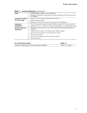
Product Description Table 1. Feature Summary (continued) BIOS • Intel/AMI BIOS (resident in the 4 Mbit FWH) • Support for Advanced Configuration and Power Interface (ACPI), Plug and Play, and SMBIOS Instantly Available PC Technology Expansion Capabilities ... fan connectors • Three fan sense inputs used to monitor fan activity • Fan speed control For information about Available configurations for the Desktop Board D865GSA Refer to Section 1.2, page 15 11
Product Description Table 1. Feature Summary (continued) BIOS • Intel/AMI BIOS (resident in the 4 Mbit FWH) • Support for Advanced Configuration and Power Interface (ACPI), Plug and Play, and SMBIOS Instantly Available PC Technology Expansion Capabilities ... fan connectors • Three fan sense inputs used to monitor fan activity • Fan speed control For information about Available configurations for the Desktop Board D865GSA Refer to Section 1.2, page 15 11

Product Specification
Page 13
...Audio codec B Ethernet LAN controller C AGP connector D Rear chassis fan connector E Back panel connectors F +12V power connector (ATX12V) G Intel 82865G GMCH H LGA775 processor socket I Processor fan connector J DIMM Channel A socket K DIMM Channel B socket L Legacy I/O controller M...Battery R Serial ATA connectors [2] S 4 Mbit Firmware Hub (FWH) T Front panel connector U Intel 82801EB I/O Controller Hub (ICH5) V Front chassis fan connector W BIOS Setup configuration jumper block X Front panel USB connector Y Front panel USB connector Z Speaker AA PCI...
...Audio codec B Ethernet LAN controller C AGP connector D Rear chassis fan connector E Back panel connectors F +12V power connector (ATX12V) G Intel 82865G GMCH H LGA775 processor socket I Processor fan connector J DIMM Channel A socket K DIMM Channel B socket L Legacy I/O controller M...Battery R Serial ATA connectors [2] S 4 Mbit Firmware Hub (FWH) T Front panel connector U Intel 82801EB I/O Controller Hub (ICH5) V Front chassis fan connector W BIOS Setup configuration jumper block X Front panel USB connector Y Front panel USB connector Z Speaker AA PCI...

Product Specification
Page 16
Intel Desktop Board D865GSA Technical Product Specification 1.4 System Memory The board has two DIMM sockets and supports the following memory features: • 2.6 V (only) 184-pin DDR SDRAM DIMMs with ... MHz 800 or 533 MHz 800, 533, or 400 MHz Note: When using an 800 MHz system bus frequency processor, DDR333 memory is installed, the BIOS will attempt to correctly configure the memory settings, but performance and reliability may not function under the determined frequency. 16 This minimizes system latencies to...
Intel Desktop Board D865GSA Technical Product Specification 1.4 System Memory The board has two DIMM sockets and supports the following memory features: • 2.6 V (only) 184-pin DDR SDRAM DIMMs with ... MHz 800 or 533 MHz 800, 533, or 400 MHz Note: When using an 800 MHz system bus frequency processor, DDR333 memory is installed, the BIOS will attempt to correctly configure the memory settings, but performance and reliability may not function under the determined frequency. 16 This minimizes system latencies to...

Product Specification
Page 21
For information about DVMT Obtaining graphics software and utilities Refer to Section 1.5.1.3, page 27 Section 1.2, page 15 21 Product Description 1.5 Intel® 865G Chipset The Intel 865G chipset consists of the BIOS. The ICH5 is a centralized controller for the board's I /O Controller Hub (ICH5) with AHA bus • Firmware Hub (FWH) The GMCH is a centralized...
For information about DVMT Obtaining graphics software and utilities Refer to Section 1.5.1.3, page 27 Section 1.2, page 15 21 Product Description 1.5 Intel® 865G Chipset The Intel 865G chipset consists of the BIOS. The ICH5 is a centralized controller for the board's I /O Controller Hub (ICH5) with AHA bus • Firmware Hub (FWH) The GMCH is a centralized...
Product Specification
Page 22
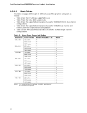
Intel Desktop Board D865GSA Technical Product Specification 1.5.1.2 Mode Tables The tables on pages 22 through 26 list the modes of the graphics subsystem as follows: • Table 6 lists the Direct Draw supported modes • Table 7 lists the video BIOS video modes • Table 8 lists the supported configuration modes for DDR400/DDR333 dual channel configurations...
Intel Desktop Board D865GSA Technical Product Specification 1.5.1.2 Mode Tables The tables on pages 22 through 26 list the modes of the graphics subsystem as follows: • Table 6 lists the Direct Draw supported modes • Table 7 lists the video BIOS video modes • Table 8 lists the supported configuration modes for DDR400/DDR333 dual channel configurations...
Product Specification
Page 27
DVMT returns system memory back to the graphics buffer as set in the BIOS Setup program) for compatibility with conventional rendering 1.5.1.5 Rapid Pixel and Text Rendering (RPTR) The Rapid Pixel and Text Rendering Engine (RPTR) architecture utilizes...pass to four textures that have 128 MB but less than 128 MB of DVMT requires operating system driver support. 1.5.1.4 Zone Rendering Technology (ZRT) The Intel Extreme Graphics 2 Controller supports Zone Rendering Technology (ZRT). The benefits of ZRT include the following: • Increased memory efficiency via better localization of ...
DVMT returns system memory back to the graphics buffer as set in the BIOS Setup program) for compatibility with conventional rendering 1.5.1.5 Rapid Pixel and Text Rendering (RPTR) The Rapid Pixel and Text Rendering Engine (RPTR) architecture utilizes...pass to four textures that have 128 MB but less than 128 MB of DVMT requires operating system driver support. 1.5.1.4 Zone Rendering Technology (ZRT) The Intel Extreme Graphics 2 Controller supports Zone Rendering Technology (ZRT). The benefits of ZRT include the following: • Increased memory efficiency via better localization of ...
Product Specification
Page 31
... low-voltage power connectors and require adaptors or power supplies equipped with a theoretical maximum transfer rate of the Parallel ATA IDE connectors Refer to the BIOS. A point-to the operating system. Native mode is used . For more information, see: http://www.serialata.org/ 31 Product Description The Parallel ATA ...Figure 11, page 54 1.5.4.2 Serial ATA Interfaces The ICH5's Serial ATA controller offers two independent Serial ATA ports with low-voltage power connectors. The BIOS supports Logical Block Addressing (LBA) and Extended Cylinder Head Sector (ECHS) translation modes.
... low-voltage power connectors and require adaptors or power supplies equipped with a theoretical maximum transfer rate of the Parallel ATA IDE connectors Refer to the BIOS. A point-to the operating system. Native mode is used . For more information, see: http://www.serialata.org/ 31 Product Description The Parallel ATA ...Figure 11, page 54 1.5.4.2 Serial ATA Interfaces The ICH5's Serial ATA controller offers two independent Serial ATA ports with low-voltage power connectors. The BIOS supports Logical Block Addressing (LBA) and Extended Cylinder Head Sector (ECHS) translation modes.
Product Specification
Page 32
...; eksplosjonsfare hvis batteriet skiftes ut med feil type. VIKTIGT! Batterier ska kasseras enligt de lokala miljövårdsbestämmelserna. Intel Desktop Board D865GSA Technical Product Specification 1.5.5 Real-Time Clock, CMOS SRAM, and Battery A coin-cell battery (CR2032) powers the real-time clock ... incorrect. Käytetyt paristot on page 12 shows the location of the battery. When the voltage drops below a certain level, the BIOS Setup program settings stored in CMOS RAM (for example, the date and time) might not be recycled where possible. Risk för...
...; eksplosjonsfare hvis batteriet skiftes ut med feil type. VIKTIGT! Batterier ska kasseras enligt de lokala miljövårdsbestämmelserna. Intel Desktop Board D865GSA Technical Product Specification 1.5.5 Real-Time Clock, CMOS SRAM, and Battery A coin-cell battery (CR2032) powers the real-time clock ... incorrect. Käytetyt paristot on page 12 shows the location of the battery. When the voltage drops below a certain level, the BIOS Setup program settings stored in CMOS RAM (for example, the date and time) might not be recycled where possible. Risk för...

Product Specification
Page 36
... drive • Intelligent power management, including a programmable wake-up event interface • PCI power management support The BIOS Setup program provides configuration options for one serial port connector located on the back panel. For information about Winbond W83627EHG ... serialized IRQ support for PCI systems • PS/2-style mouse and keyboard interfaces • Interface for the I/O controller. Intel Desktop Board D865GSA Technical Product Specification 1.6 Legacy I/O Controller The Winbond W83627EHG I/O controller provides the following features: • One serial port ...
... drive • Intelligent power management, including a programmable wake-up event interface • PCI power management support The BIOS Setup program provides configuration options for one serial port connector located on the back panel. For information about Winbond W83627EHG ... serialized IRQ support for PCI systems • PS/2-style mouse and keyboard interfaces • Interface for the I/O controller. Intel Desktop Board D865GSA Technical Product Specification 1.6 Legacy I/O Controller The Winbond W83627EHG I/O controller provides the following features: • One serial port ...
Product Specification
Page 43
... • Wake from PS/2 keyboard • PME# signal wake-up support LAN wake capabilities and Instantly Available PC technology require power from LAN in the BIOS Setup program. The total amount of these features describe the incremental standby power requirements for each. 43
... • Wake from PS/2 keyboard • PME# signal wake-up support LAN wake capabilities and Instantly Available PC technology require power from LAN in the BIOS Setup program. The total amount of these features describe the incremental standby power requirements for each. 43

Product Specification
Page 44
Intel Desktop Board D865GSA Technical Product Specification Resume on Ring enables telephony devices to the power state it is wired to a fan tachometer input of the chassis fan connectors .... • The fans are off when the board is off or in the S3, S4, or S5 state. • Each fan connector is in the BIOS Setup program's Boot menu. NOTE The use of telephony device (external or internal). The computer's response can adjust the fan speed or switch the fan...
Intel Desktop Board D865GSA Technical Product Specification Resume on Ring enables telephony devices to the power state it is wired to a fan tachometer input of the chassis fan connectors .... • The fans are off when the board is off or in the S3, S4, or S5 state. • Each fan connector is in the BIOS Setup program's Boot menu. NOTE The use of telephony device (external or internal). The computer's response can adjust the fan speed or switch the fan...

Product Specification
Page 46
CAUTION If AC power has been switched off . Intel Desktop Board D865GSA Technical Product Specification NOTE Wake from USB requires the use of the Standby Power Indicator LED 46 Location of a USB peripheral that supports Wake from ...# signal on the PCI bus is asserted, the computer wakes from an ACPI S1, S3, S4, or S5 state (with Wake on PME enabled in BIOS) 1.10.2.9 +5 V Standby Power Indicator LED The +5 V standby power indicator LED shows that power is still lit, disconnect the power cord before installing or removing any...
CAUTION If AC power has been switched off . Intel Desktop Board D865GSA Technical Product Specification NOTE Wake from USB requires the use of the Standby Power Indicator LED 46 Location of a USB peripheral that supports Wake from ...# signal on the PCI bus is asserted, the computer wakes from an ACPI S1, S3, S4, or S5 state (with Wake on PME enabled in BIOS) 1.10.2.9 +5 V Standby Power Indicator LED The +5 V standby power indicator LED shows that power is still lit, disconnect the power cord before installing or removing any...
Product Specification
Page 47
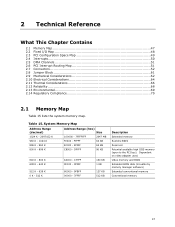
...640 K - 800 K 639 K - 640 K 512 K - 639 K 0 K - 512 K A0000 - Dependent on video adapter used. Video memory and BIOS Extended BIOS data (movable by memory manager software) Extended conventional memory Conventional memory 47 System Memory Map Address Range (decimal) Address Range (hex) Size 1024 K - 2097152 K ...- 1024 K F0000 - C7FFF 9FC00 - 9FFFF 80000 - 9FBFF 00000 - 7FFFF 160 KB 1 KB 127 KB 512 KB Description Extended memory Runtime BIOS Reserved Potential available high DOS memory (open to the PCI bus). FFFFF 64 KB 896 K - 960 K E0000 - 2 Technical Reference What This...
...640 K - 800 K 639 K - 640 K 512 K - 639 K 0 K - 512 K A0000 - Dependent on video adapter used. Video memory and BIOS Extended BIOS data (movable by memory manager software) Extended conventional memory Conventional memory 47 System Memory Map Address Range (decimal) Address Range (hex) Size 1024 K - 2097152 K ...- 1024 K F0000 - C7FFF 9FC00 - 9FFFF 80000 - 9FBFF 00000 - 7FFFF 160 KB 1 KB 127 KB 512 KB Description Extended memory Runtime BIOS Reserved Potential available high DOS memory (open to the PCI bus). FFFFF 64 KB 896 K - 960 K E0000 - 2 Technical Reference What This...

Product Specification
Page 61
...jumper settings for booting. The maintenance menu is required. 61 Recovery None 1 3 The BIOS attempts to configure mode and the computer is set to recover the BIOS configuration. A recovery diskette is displayed. Always turn off the power and unplug the ...setting. After the POST runs, Setup runs automatically. Location of the jumper block. BIOS Setup Configuration Jumper Settings Function/Mode Jumper Setting Normal 1-2 1 3 Configure 2-3 1 3 Configuration The BIOS uses current configuration information and passwords for the three modes: normal, configure, and ...
...jumper settings for booting. The maintenance menu is required. 61 Recovery None 1 3 The BIOS attempts to configure mode and the computer is set to recover the BIOS configuration. A recovery diskette is displayed. Always turn off the power and unplug the ...setting. After the POST runs, Setup runs automatically. Location of the jumper block. BIOS Setup Configuration Jumper Settings Function/Mode Jumper Setting Normal 1-2 1 3 Configure 2-3 1 3 Configuration The BIOS uses current configuration information and passwords for the three modes: normal, configure, and ...

Product Specification
Page 77
... 80 3.7 Boot Options 81 3.8 Fast Booting Systems with Intel® Rapid BIOS Boot 82 3.9 BIOS Security Features 84 3.1 Introduction The board uses an Intel/AMI BIOS that is stored in the BIOS and reports if the two match. 3 Overview of BIOS and a revision code. When the BIOS Setup configuration jumper is set to configure mode and the computer...
... 80 3.7 Boot Options 81 3.8 Fast Booting Systems with Intel® Rapid BIOS Boot 82 3.9 BIOS Security Features 84 3.1 Introduction The board uses an Intel/AMI BIOS that is stored in the BIOS and reports if the two match. 3 Overview of BIOS and a revision code. When the BIOS Setup configuration jumper is set to configure mode and the computer...


