
Product Specification
Page 3
... the BIOS Setup program's menus and submenus A description of the BIOS error messages, beep codes, and POST codes Typographical Conventions This section contains information about the D845BG and D845PT boards and their components to the vendors, system integrators, and other engineers and technicians.... What This Document Contains Chapter 1 2 3 4 5 Description A description of the hardware used in all of these Intel® Desktop Boards: D845BG and D845PT. Notes, Cautions, and Warnings ✏ NOTE Notes call attention to help you avoid damaging hardware or losing data. CAUTION...
... the BIOS Setup program's menus and submenus A description of the BIOS error messages, beep codes, and POST codes Typographical Conventions This section contains information about the D845BG and D845PT boards and their components to the vendors, system integrators, and other engineers and technicians.... What This Document Contains Chapter 1 2 3 4 5 Description A description of the hardware used in all of these Intel® Desktop Boards: D845BG and D845PT. Notes, Cautions, and Warnings ✏ NOTE Notes call attention to help you avoid damaging hardware or losing data. CAUTION...
Product Specification
Page 7
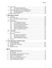
... 4. USB 1.1 Port Configuration 27 7. Intel 845 Chipset Block Diagram 25 6. Block Diagram with Intel® Rapid BIOS Boot 96 3.9.1 Peripheral Selection and Configuration 96 3.9.2 Intel Rapid BIOS Boot 97 3.10 BIOS Security...Beep Codes ...128 Figures 1. ICH2 and CNR Signal Interface 36 vii Audio Subsystem Block Diagram 33 9. USB 2.0 Port Configuration (Optional 28 8. D845BG Board Components 14 2. Contents 3.8 Boot Options...96 3.8.1 CD-ROM and Network Boot 96 3.8.2 Booting Without Attached Devices 96 3.9 Fast Booting Systems with Optional USB 2.0 Support 17 5. D845PT...
... 4. USB 1.1 Port Configuration 27 7. Intel 845 Chipset Block Diagram 25 6. Block Diagram with Intel® Rapid BIOS Boot 96 3.9.1 Peripheral Selection and Configuration 96 3.9.2 Intel Rapid BIOS Boot 97 3.10 BIOS Security...Beep Codes ...128 Figures 1. ICH2 and CNR Signal Interface 36 vii Audio Subsystem Block Diagram 33 9. USB 2.0 Port Configuration (Optional 28 8. D845BG Board Components 14 2. Contents 3.8 Boot Options...96 3.8.1 CD-ROM and Network Boot 96 3.8.2 Booting Without Attached Devices 96 3.9 Fast Booting Systems with Optional USB 2.0 Support 17 5. D845PT...
Product Specification
Page 10
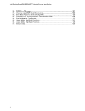
Beep Codes...129 x Uncompressed INIT Code Checkpoints 123 82. Runtime Code Uncompressed in F000 Shadow RAM 124 84. Bus Initialization Checkpoints 127 85. Upper Nibble High Byte Functions 127 86. Intel Desktop Board D845BG/D845PT Technical Product Specification 80. Lower Nibble High Byte Functions 128 87. Boot Block Recovery Code Checkpoints 123 83. BIOS Error Messages 121 81.
Beep Codes...129 x Uncompressed INIT Code Checkpoints 123 82. Runtime Code Uncompressed in F000 Shadow RAM 124 84. Bus Initialization Checkpoints 127 85. Upper Nibble High Byte Functions 127 86. Intel Desktop Board D845BG/D845PT Technical Product Specification 80. Lower Nibble High Byte Functions 128 87. Boot Block Recovery Code Checkpoints 123 83. BIOS Error Messages 121 81.

Product Specification
Page 95
...Information about The BIOS recovery mode jumper settings The Boot menu in the BIOS Setup program Contacting Intel customer support Refer to Section 1.3, page 18 3.7 Recovering BIOS Data Some types of continuous beeps indicates a failed BIOS recovery. When recovering the BIOS, be aware of the following: &#... can be replaced with creating a custom splash screen. BIOS upgrades and the Intel Flash Memory Update Utility are supported in five languages: US English, German, Italian, French, and Spanish. Overview of code available in the non-erasable boot block area, there is no video support....
...Information about The BIOS recovery mode jumper settings The Boot menu in the BIOS Setup program Contacting Intel customer support Refer to Section 1.3, page 18 3.7 Recovering BIOS Data Some types of continuous beeps indicates a failed BIOS recovery. When recovering the BIOS, be aware of the following: &#... can be replaced with creating a custom splash screen. BIOS upgrades and the Intel Flash Memory Update Utility are supported in five languages: US English, German, Italian, French, and Spanish. Overview of code available in the non-erasable boot block area, there is no video support....

Product Specification
Page 121
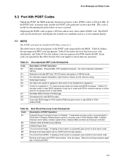
... the same as the last boot. Error occurred trying to set correct values. 5 Error Messages and Beep Codes What This Chapter Contains 5.1 BIOS Error Messages 121 5.2 Port 80h POST Codes 123 5.3 Bus Initialization Checkpoints 127 5.4 Speaker ...128 5.5 BIOS Beep Codes ...128 5.1 BIOS Error Messages Table 80 lists the error messages and provides a brief description of...
... the same as the last boot. Error occurred trying to set correct values. 5 Error Messages and Beep Codes What This Chapter Contains 5.1 BIOS Error Messages 121 5.2 Port 80h POST Codes 123 5.3 Bus Initialization Checkpoints 127 5.4 Speaker ...128 5.5 BIOS Beep Codes ...128 5.1 BIOS Error Messages Table 80 lists the error messages and provides a brief description of...
Product Specification
Page 123
... controller. Booting from floppy. Give two beeps. Error Messages and Beep Codes 5.2 Port 80h POST Codes During the POST, the BIOS generates diagnostic progress codes (POST-codes) to 4 GB flat mode. Onboard KBC, RTC enabled (if present). Uncompress the main BIOS module. Table 82. Initialize extra (Intel Recovery) Module. Displaying the POST-codes requires a PCI bus add-in...
... controller. Booting from floppy. Give two beeps. Error Messages and Beep Codes 5.2 Port 80h POST Codes During the POST, the BIOS generates diagnostic progress codes (POST-codes) to 4 GB flat mode. Onboard KBC, RTC enabled (if present). Uncompress the main BIOS module. Table 82. Initialize extra (Intel Recovery) Module. Displaying the POST-codes requires a PCI bus add-in...

Product Specification
Page 125
...of POST Operation To prepare the descriptor tables. Going to write patterns in F000 Shadow RAM (continued) Code 40 42 43 44 45 46 47 48 49 4B 4C 4D 4E 4F 50 51 52 53 54... interface test command. To write command byte and init circular buffer. Error Messages and Beep Codes Table 83. Memory size display started . Memory size adjusted for lock-key. To program DMA unit 1 and 2. ...continued 125 Runtime Code Uncompressed in base 640k memory. Keyboard test started . Command byte written, global data init done. To...
...of POST Operation To prepare the descriptor tables. Going to write patterns in F000 Shadow RAM (continued) Code 40 42 43 44 45 46 47 48 49 4B 4C 4D 4E 4F 50 51 52 53 54... interface test command. To write command byte and init circular buffer. Error Messages and Beep Codes Table 83. Memory size display started . Memory size adjusted for lock-key. To program DMA unit 1 and 2. ...continued 125 Runtime Code Uncompressed in base 640k memory. Keyboard test started . Command byte written, global data init done. To...

Product Specification
Page 127
...different bus routines, additional checkpoints are output to port 80h as WORD to identify the routines under execution. Going to copy any code to do various tasks. Table 84. Bus Initialization Checkpoints Checkpoint Description 2A Different buses init (system, static, and output devices... buses initialization error messages. 95 Init of POST Operation Uncompress SMBIOS module and init SMBIOS code and form the runtime SMBIOS image in the different buses. Error Messages and Beep Codes Table 83. Table 85. Upper Nibble High Byte Functions Value Description 0 func#0, disable ...
...different bus routines, additional checkpoints are output to port 80h as WORD to identify the routines under execution. Going to copy any code to do various tasks. Table 84. Bus Initialization Checkpoints Checkpoint Description 2A Different buses init (system, static, and output devices... buses initialization error messages. 95 Init of POST Operation Uncompress SMBIOS module and init SMBIOS code and form the runtime SMBIOS image in the different buses. Error Messages and Beep Codes Table 83. Table 85. Upper Nibble High Byte Functions Value Description 0 func#0, disable ...

Product Specification
Page 128
... the screen (using both monochrome and color adapters). 128 Intel Desktop Board D845BG/D845PT Technical Product Specification Table 86 describes the lower nibble of the high byte and indicates the bus on the D845BG and the D845PT board. Table 86. The speaker provides audible error code (beep code) information during POST, the BIOS displays an error...
... the screen (using both monochrome and color adapters). 128 Intel Desktop Board D845BG/D845PT Technical Product Specification Table 86 describes the lower nibble of the high byte and indicates the bus on the D845BG and the D845PT board. Table 86. The speaker provides audible error code (beep code) information during POST, the BIOS displays an error...

Product Specification
Page 129
POST module not found, etc.) 129 Error Messages and Beep Codes If POST completes normally, the BIOS issues one short beep before passing control to the operating system. Beep Codes Beep Description 1 Refresh failure 2 Parity cannot be reset 3 First 64 KB memory failure 4 Timer not operational 5 Not used 6 8042 GateA20 cannot be toggled 7 Exception interrupt error 8 Display memory R/W error 9 Not used 10 CMOS Shutdown register test error 11 Invalid BIOS (e.g. Table 87.
POST module not found, etc.) 129 Error Messages and Beep Codes If POST completes normally, the BIOS issues one short beep before passing control to the operating system. Beep Codes Beep Description 1 Refresh failure 2 Parity cannot be reset 3 First 64 KB memory failure 4 Timer not operational 5 Not used 6 8042 GateA20 cannot be toggled 7 Exception interrupt error 8 Display memory R/W error 9 Not used 10 CMOS Shutdown register test error 11 Invalid BIOS (e.g. Table 87.

Intel Desktop Board D845PT/D845BG Product Guide
Page 5
...Map ...74 DMA Channels ...74 I /O Shield 24 5. Installing the I /O Map ...75 Interrupts ...77 A Error Messages and Indicators BIOS Beep Codes ...79 BIOS Error Messages ...80 B Regulatory Compliance Safety Regulations ...83 EMC Regulations ...83 Product Certification Markings 84 Installation Precautions ...85 Installation Instructions...Only for Intended Applications 87 Figures 1. Installing the Processor Fan Heatsink RM Base to the Board 28 9. D845PT Board Components 11 2. Pressing Down the Pushpin 28 10. D845BG Board Mounting Holes 26 7. Processor Fan Heatsink RM Mounting Holes...
...Map ...74 DMA Channels ...74 I /O Shield 24 5. Installing the I /O Map ...75 Interrupts ...77 A Error Messages and Indicators BIOS Beep Codes ...79 BIOS Error Messages ...80 B Regulatory Compliance Safety Regulations ...83 EMC Regulations ...83 Product Certification Markings 84 Installation Precautions ...85 Installation Instructions...Only for Intended Applications 87 Figures 1. Installing the Processor Fan Heatsink RM Base to the Board 28 9. D845PT Board Components 11 2. Pressing Down the Pushpin 28 10. D845BG Board Mounting Holes 26 7. Processor Fan Heatsink RM Mounting Holes...
Intel Desktop Board D845PT/D845BG Product Guide
Page 19
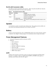
...On (steady state) On (brighter and pulsing) Indicates 10 Mbit/sec data rate is selected. 100 Mbit/sec data rate is communicating with the D845PT or D845BG board requires an operating system that provides full ACPI support. 19 Table 3. The computer is selected. Speaker A 47 Ω inductive ...over the power management and Plug & Play functions of ACPI with another computer on how to replace the battery. The speaker provides audible error code (beep code) information during the Power-On Self-Test (POST). Table 3 describes the LED states when the board is powered up and the LAN ...
...On (steady state) On (brighter and pulsing) Indicates 10 Mbit/sec data rate is selected. 100 Mbit/sec data rate is communicating with the D845PT or D845BG board requires an operating system that provides full ACPI support. 19 Table 3. The computer is selected. Speaker A 47 Ω inductive ...over the power management and Plug & Play functions of ACPI with another computer on how to replace the battery. The speaker provides audible error code (beep code) information during the Power-On Self-Test (POST). Table 3 describes the LED states when the board is powered up and the LAN ...

Intel Desktop Board D845PT/D845BG Product Guide
Page 45
... will not see anything will cease (temporarily) indicating the successful recovery of code available in drive A, replace the computer cover, and connect the computer's power cord. 12. In about a minute, two beeps will be damaged. If recovery is unlikely that anything on the screen during...On the jumper block (J6F2), reinstall the jumper back on pins 1-2 as shown below to set recovery mode for more beeps indicating the successful recovery of continuous beeps indicates a failed BIOS recovery. 7. however, if an interruption occurs, the BIOS could be heard and drive A activity...
... will not see anything will cease (temporarily) indicating the successful recovery of code available in drive A, replace the computer cover, and connect the computer's power cord. 12. In about a minute, two beeps will be damaged. If recovery is unlikely that anything on the screen during...On the jumper block (J6F2), reinstall the jumper back on pins 1-2 as shown below to set recovery mode for more beeps indicating the successful recovery of continuous beeps indicates a failed BIOS recovery. 7. however, if an interruption occurs, the BIOS could be heard and drive A activity...

Intel Desktop Board D845PT/D845BG Product Guide
Page 79
...Reserved; not used ) 10 CMOS Shutdown register test error 11 Invalid BIOS (such as, POST module not found) 79 The BIOS also issues a beep code (one long tone followed by two short tones) during POST if the video configuration fails (a faulty video card or no card installed) or if ...an external ROM module does not properly checksum to zero. A Error Messages and Indicators The D845PT and D845BG boards report POST errors in two ways: • By sounding a beep code • By displaying an error message on the monitor BIOS Beep Codes The BIOS beep codes are listed in Table 36.
...Reserved; not used ) 10 CMOS Shutdown register test error 11 Invalid BIOS (such as, POST module not found) 79 The BIOS also issues a beep code (one long tone followed by two short tones) during POST if the video configuration fails (a faulty video card or no card installed) or if ...an external ROM module does not properly checksum to zero. A Error Messages and Indicators The D845PT and D845BG boards report POST errors in two ways: • By sounding a beep code • By displaying an error message on the monitor BIOS Beep Codes The BIOS beep codes are listed in Table 36.


