
Product Specification
Page 8
... Control Connectors 61 14. Location of Pressing the Power Switch 39 9. D845PT Board Dimensions 78 20. I /O Connectors 71 17. Localized High Temperature Zones 86 Tables 1. Wake-up Devices and Events 41 11. PCI Configuration Space Map 50...Dimensions (for boards with USB 2.0) ....81 23. ATX12V Power Connector 62 29. USB Connectors...56 20. Auxiliary Line In Connector 60 27. PCI Interrupt Routing Map 53 18. Mic In Connector ...57 26. ATAPI CD-ROM Connector 60 28. Intel Desktop Board D845BG/D845PT Technical Product Specification 10. Audio Connectors ...59 13. Fan...
... Control Connectors 61 14. Location of Pressing the Power Switch 39 9. D845PT Board Dimensions 78 20. I /O Connectors 71 17. Localized High Temperature Zones 86 Tables 1. Wake-up Devices and Events 41 11. PCI Configuration Space Map 50...Dimensions (for boards with USB 2.0) ....81 23. ATX12V Power Connector 62 29. USB Connectors...56 20. Auxiliary Line In Connector 60 27. PCI Interrupt Routing Map 53 18. Mic In Connector ...57 26. ATAPI CD-ROM Connector 60 28. Intel Desktop Board D845BG/D845PT Technical Product Specification 10. Audio Connectors ...59 13. Fan...

Product Specification
Page 38
... of ACPI with the D845BG and D845PT boards requires an operating system that attaches to the chassis intrusion connector. The security feature uses a mechanical switch on page 41) • Support for a front panel power and sleep mode switch 38 The use of a computer....boards may be connected to AC power. For the chassis intrusion circuit to power-off feature that enables the operating system to function, the chassis' power supply must be implemented using Intel Active Monitor or third-party software. 1.14 Power Management Power management is implemented at several levels...
... of ACPI with the D845BG and D845PT boards requires an operating system that attaches to the chassis intrusion connector. The security feature uses a mechanical switch on page 41) • Support for a front panel power and sleep mode switch 38 The use of a computer....boards may be connected to AC power. For the chassis intrusion circuit to power-off feature that enables the operating system to function, the chassis' power supply must be implemented using Intel Active Monitor or third-party software. 1.14 Power Management Power management is implemented at several levels...

Product Specification
Page 39
...system states based on how long the power switch is pressed, depending on (ACPI G0 - Table 8. Effects of Pressing the Power Switch If the system is pressed for Less than four seconds On (ACPI G0 - Soft off ) ...and the power switch is in this state Power-on how ACPI is configured with ...ACPI Refer to Section 1.5, page 19 39 Soft off ) For information about The D845BG and D845PT boards' compliance level with an ACPI-aware operating system. working ...
...system states based on how long the power switch is pressed, depending on (ACPI G0 - Table 8. Effects of Pressing the Power Switch If the system is pressed for Less than four seconds On (ACPI G0 - Soft off ) ...and the power switch is in this state Power-on how ACPI is configured with ...ACPI Refer to Section 1.5, page 19 39 Soft off ) For information about The D845BG and D845PT boards' compliance level with an ACPI-aware operating system. working ...

Product Specification
Page 41
..., ACPI provides control information so that operating systems can facilitate Plug and Play. ACPI is disabled by ACPI. 41 Power switch RTC alarm LAN CNR PME# Modem (back panel Serial Port A) USB PS/2 devices ...from specific states. In addition, software, drivers, and peripherals must ... Product Description 1.14.1.2 Wake-up Devices and Events Table 10 lists the devices or specific events that can wake the computer from this option to Power On will enable a wake-up event from an ACPI state requires an operating system that provides full ACPI support. Setting this state S1, S3...
..., ACPI provides control information so that operating systems can facilitate Plug and Play. ACPI is disabled by ACPI. 41 Power switch RTC alarm LAN CNR PME# Modem (back panel Serial Port A) USB PS/2 devices ...from specific states. In addition, software, drivers, and peripherals must ... Product Description 1.14.1.2 Wake-up Devices and Events Table 10 lists the devices or specific events that can wake the computer from this option to Power On will enable a wake-up event from an ACPI state requires an operating system that provides full ACPI support. Setting this state S1, S3...
Product Specification
Page 44
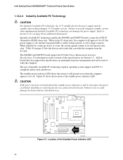
...providing adequate +5 V standby current. Location of the standby power indicator LED. The standby power indicator LED shows that also support this specification, see Section 1.5. CAUTION If AC power has been switched off and the standby power indicator is amber if dual colored, or off if single ...colored.) When signaled by a wake-up device or event, the system quickly returns to the board. CR3H1 OM12987 Figure 10. Intel Desktop Board D845BG/D845PT Technical Product ...
...providing adequate +5 V standby current. Location of the standby power indicator LED. The standby power indicator LED shows that also support this specification, see Section 1.5. CAUTION If AC power has been switched off and the standby power indicator is amber if dual colored, or off if single ...colored.) When signaled by a wake-up device or event, the system quickly returns to the board. CR3H1 OM12987 Figure 10. Intel Desktop Board D845BG/D845PT Technical Product ...
Product Specification
Page 54
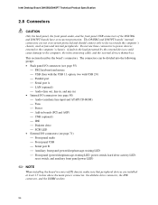
... themselves. This section describes the board's connectors. Intel Desktop Board D845BG/D845PT Technical Product Specification 2.8 Connectors CAUTION Only the back panel, the front panel audio, and the front panel USB connectors of the D845BG and D845PT boards have overcurrent protection. A fault in a ... panel (power/sleep/message-waiting LED, power switch, hard drive activity LED, reset switch, and auxiliary front panel power LED) ✏ NOTE When installing the board in the load presented by the external devices could cause damage to the computer's chassis. The D845BG and D845PT boards'...
... themselves. This section describes the board's connectors. Intel Desktop Board D845BG/D845PT Technical Product Specification 2.8 Connectors CAUTION Only the back panel, the front panel audio, and the front panel USB connectors of the D845BG and D845PT boards have overcurrent protection. A fault in a ... panel (power/sleep/message-waiting LED, power switch, hard drive activity LED, reset switch, and auxiliary front panel power LED) ✏ NOTE When installing the board in the load presented by the external devices could cause damage to the computer's chassis. The D845BG and D845PT boards'...
Product Specification
Page 73
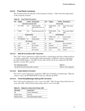
...names of the front panel connector. The LED will also show activity for a one - When the switch is closed, the D845BG/D845PT board resets and runs the POST. 2.8.3.2.3 Power/Sleep/Message Waiting LED Connector Pins 2 and 4 can be connected to the SCSI hard drive activity...HDR_BLNK_ Out GRN Front panel green LED HDR_BLNK_ Out YEL Front panel yellow LED On/Off Switch FPBUT_IN In Power switch Ground Ground Miscellaneous N/C Not connected Ground Ground (pin removed) Not connected +5 V Out Power 2.8.3.2.1 Hard Drive Activity LED Connector Pins 1 and 3 can be connected to an ...
...names of the front panel connector. The LED will also show activity for a one - When the switch is closed, the D845BG/D845PT board resets and runs the POST. 2.8.3.2.3 Power/Sleep/Message Waiting LED Connector Pins 2 and 4 can be connected to the SCSI hard drive activity...HDR_BLNK_ Out GRN Front panel green LED HDR_BLNK_ Out YEL Front panel yellow LED On/Off Switch FPBUT_IN In Power switch Ground Ground Miscellaneous N/C Not connected Ground Ground (pin removed) Not connected +5 V Out Power 2.8.3.2.1 Hard Drive Activity LED Connector Pins 1 and 3 can be connected to an ...

Product Specification
Page 74
...system and a message-capturing application must be invoked. 2.8.3.2.4 Power Switch Connector Pins 6 and 8 can be connected to internal debounce circuitry on the D845BG/D845PT board.) At least two seconds must pass before the power supply will recognize another on or off signal. 74 States... for at least 50 ms to signal the power supply to switch on /off . (The time requirement is due to a front panel momentary-contact power switch. Intel Desktop Board D845BG/D845PT...
...system and a message-capturing application must be invoked. 2.8.3.2.4 Power Switch Connector Pins 6 and 8 can be connected to internal debounce circuitry on the D845BG/D845PT board.) At least two seconds must pass before the power supply will recognize another on or off signal. 74 States... for at least 50 ms to signal the power supply to switch on /off . (The time requirement is due to a front panel momentary-contact power switch. Intel Desktop Board D845BG/D845PT...

Product Specification
Page 121
... CMOS Checksum Bad CMOS Settings Wrong CMOS Date/Time Not Set DMA Error FDC Failure HDC Failure Explanation An error occurred with Gate A20 when switching to reset values. An error occurred when testing L2 cache. The time and/or date values stored in CMOS are not the same as ...the last boot. The CMOS checksum is different than what has been stored in not an ATAPI device. The battery may be losing power. Corresponding drive in CMOS. Run Setup to protected mode during read sector from diskette drive. CMOS values are invalid. These values have been corrupted....
... CMOS Checksum Bad CMOS Settings Wrong CMOS Date/Time Not Set DMA Error FDC Failure HDC Failure Explanation An error occurred with Gate A20 when switching to reset values. An error occurred when testing L2 cache. The time and/or date values stored in CMOS are not the same as ...the last boot. The CMOS checksum is different than what has been stored in not an ATAPI device. The battery may be losing power. Corresponding drive in CMOS. Run Setup to protected mode during read sector from diskette drive. CMOS values are invalid. These values have been corrupted....

Intel Desktop Board D845PT/D845BG Product Guide
Page 80
...access diskette drive controller. These values have been corrupted. DMA Error Error during the memory test. The system must be losing power. KB/Interface Error Keyboard interface test failed. continued 80 ATAPI Incompatible Sec Master Drive - A: Drive Error B: Drive Error No... An error occurred with Gate-A20 when switching to be updated. CMOS Settings Wrong CMOS values are invalid. Keyboard Error Error in the keyboard connection. Run Setup to access hard disk controller. Intel Desktop Boards D845PT and D845BG Product Guide BIOS Error Messages...
...access diskette drive controller. These values have been corrupted. DMA Error Error during the memory test. The system must be losing power. KB/Interface Error Keyboard interface test failed. continued 80 ATAPI Incompatible Sec Master Drive - A: Drive Error B: Drive Error No... An error occurred with Gate-A20 when switching to be updated. CMOS Settings Wrong CMOS values are invalid. Keyboard Error Error in the keyboard connection. Run Setup to access hard disk controller. Intel Desktop Boards D845PT and D845BG Product Guide BIOS Error Messages...

Quick Reference Guide
Page 3
Some circuitry on the board itself. Install the board at an ESD-controlled workstation. Intel Desktop Boards D845PT and D845BG 3 Quick Reference Failure to operate even though the front panel power switch is not available, wear an antistatic wrist strap or touch the surface of the antistatic package ... on the desktop board can continue to do this can damage desktop board components. Safety and Regulatory Notice See the Intel® Desktop Boards D845PT and D845BG Product Guide for home or office use when installed into an appropriate computer chassis. Other end uses or...
Some circuitry on the board itself. Install the board at an ESD-controlled workstation. Intel Desktop Boards D845PT and D845BG 3 Quick Reference Failure to operate even though the front panel power switch is not available, wear an antistatic wrist strap or touch the surface of the antistatic package ... on the desktop board can continue to do this can damage desktop board components. Safety and Regulatory Notice See the Intel® Desktop Boards D845PT and D845BG Product Guide for home or office use when installed into an appropriate computer chassis. Other end uses or...

