
Product Specification
Page 5
...Overview ...12 1.2.1 Feature Summary 12 1.2.2 Manufacturing Options 13 1.2.3 Board Layouts 14 1.2.4 Block Diagram 16 1.3 Online Support ...18 1.4 Operating System Support 18 1.5 Design Specifications 19 1.6 Processor ...22 1.7 System Memory ...23 1.8 Intel® 845 Chipset...25 1.8.1 AGP ...26 1.8.2 USB...27 1.8.3 IDE Support 29 1.8.4...Audio Subsystem...33 1.10.1 Audio Connectors 34 1.10.2 Audio Subsystem Software 34 1.11 LAN Subsystem (Optional 35 1.11.1 Intel® 82562ET Platform LAN Connect Device 35 1.11.2 RJ-45 LAN Connector with Integrated LEDs 35 1.11.3 LAN Subsystem ...
...Overview ...12 1.2.1 Feature Summary 12 1.2.2 Manufacturing Options 13 1.2.3 Board Layouts 14 1.2.4 Block Diagram 16 1.3 Online Support ...18 1.4 Operating System Support 18 1.5 Design Specifications 19 1.6 Processor ...22 1.7 System Memory ...23 1.8 Intel® 845 Chipset...25 1.8.1 AGP ...26 1.8.2 USB...27 1.8.3 IDE Support 29 1.8.4...Audio Subsystem...33 1.10.1 Audio Connectors 34 1.10.2 Audio Subsystem Software 34 1.11 LAN Subsystem (Optional 35 1.11.1 Intel® 82562ET Platform LAN Connect Device 35 1.11.2 RJ-45 LAN Connector with Integrated LEDs 35 1.11.3 LAN Subsystem ...
Product Specification
Page 7
D845BG Board Components 14 2. ICH2 and CNR Signal Interface 36 vii Block Diagram ...16 4. Block Diagram with Intel® Rapid BIOS Boot 96 3.9.1 Peripheral Selection and Configuration 96 3.9.2 Intel Rapid BIOS Boot 97 3.10 BIOS Security Features 98 4 BIOS Setup Program 4.1 Introduction...99 4.2 ... 80h POST Codes 123 5.3 Bus Initialization Checkpoints 127 5.4 Speaker ...128 5.5 BIOS Beep Codes ...128 Figures 1. Audio Subsystem Block Diagram 33 9. Contents 3.8 Boot Options...96 3.8.1 CD-ROM and Network Boot 96 3.8.2 Booting Without Attached Devices 96 3.9 Fast Booting Systems ...
D845BG Board Components 14 2. ICH2 and CNR Signal Interface 36 vii Block Diagram ...16 4. Block Diagram with Intel® Rapid BIOS Boot 96 3.9.1 Peripheral Selection and Configuration 96 3.9.2 Intel Rapid BIOS Boot 97 3.10 BIOS Security Features 98 4 BIOS Setup Program 4.1 Introduction...99 4.2 ... 80h POST Codes 123 5.3 Bus Initialization Checkpoints 127 5.4 Speaker ...128 5.5 BIOS Beep Codes ...128 Figures 1. Audio Subsystem Block Diagram 33 9. Contents 3.8 Boot Options...96 3.8.1 CD-ROM and Network Boot 96 3.8.2 Booting Without Attached Devices 96 3.9 Fast Booting Systems ...
Product Specification
Page 16
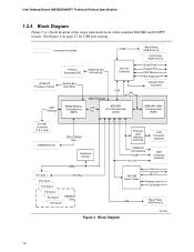
Block Diagram OM13008 16 See Figure 6 on page 27 for USB port routing. = connector or socket USB Primary/ Secondary IDE UDMA 33 and ATA-66/100 LPC I/O ... AC Link CNR Connector (optional) AD1885 Audio Codec Line In Line Out Mic In Auxiliary Line In CD-ROM USB Back Panel USB Ports (2) Figure 3. Intel Desktop Board D845BG/D845PT Technical Product Specification 1.2.4 Block Diagram Figure 3 is a block diagram of the major functional areas of the standard D845BG and...
Block Diagram OM13008 16 See Figure 6 on page 27 for USB port routing. = connector or socket USB Primary/ Secondary IDE UDMA 33 and ATA-66/100 LPC I/O ... AC Link CNR Connector (optional) AD1885 Audio Codec Line In Line Out Mic In Auxiliary Line In CD-ROM USB Back Panel USB Ports (2) Figure 3. Intel Desktop Board D845BG/D845PT Technical Product Specification 1.2.4 Block Diagram Figure 3 is a block diagram of the major functional areas of the standard D845BG and...

Product Specification
Page 17
... Mic In Auxiliary Line In CD-ROM NEC µPD720100 USB 2.0 Host Controller USB USB Back Panel USB Ports (2) Front Panel USB Ports (2) Figure 4. Block Diagram with the USB 2.0 manufacturing option. Product Description Figure 4 is a block diagram of the major functional areas of the D845BG board with Optional USB 2.0 Support OM13009 17
... Mic In Auxiliary Line In CD-ROM NEC µPD720100 USB 2.0 Host Controller USB USB Back Panel USB Ports (2) Front Panel USB Ports (2) Figure 4. Block Diagram with the USB 2.0 manufacturing option. Product Description Figure 4 is a block diagram of the major functional areas of the D845BG board with Optional USB 2.0 Support OM13009 17
Product Specification
Page 25
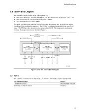
...) AGP DDR SDRAM Interface Bus LPC Bus SMBus PCI Bus AC Link Figure 5. The component combination provides the chipset interfaces as shown in Figure 5. Intel 845 Chipset Block Diagram OM13069 ✏ NOTE The USB bus is routed from the NEC USB 2.0 controller if the USB 2.0 option is a centralized controller for the board...
...) AGP DDR SDRAM Interface Bus LPC Bus SMBus PCI Bus AC Link Figure 5. The component combination provides the chipset interfaces as shown in Figure 5. Intel 845 Chipset Block Diagram OM13069 ✏ NOTE The USB bus is routed from the NEC USB 2.0 controller if the USB 2.0 option is a centralized controller for the board...
Product Specification
Page 33
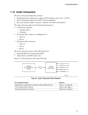
Audio Subsystem Block Diagram OM13010 For information about Upgrading the onboard audio subsystem using a CNR audio card The front panel audio connector The back panel audio connectors Refer to -...; Mic in pre-amp that supports dynamic, condenser, and electret microphones The audio subsystem supports the following devices: • Intel 82801BA I/O Controller Hub (ICH2) • Analog Devices AD1885 audio codec Figure 8 is a block diagram of the audio subsystem. 82801BA I/O Controller Hub (ICH2) AC '97 Link AD1885 Audio Codec Line In Line Out...
Audio Subsystem Block Diagram OM13010 For information about Upgrading the onboard audio subsystem using a CNR audio card The front panel audio connector The back panel audio connectors Refer to -...; Mic in pre-amp that supports dynamic, condenser, and electret microphones The audio subsystem supports the following devices: • Intel 82801BA I/O Controller Hub (ICH2) • Analog Devices AD1885 audio codec Figure 8 is a block diagram of the audio subsystem. 82801BA I/O Controller Hub (ICH2) AC '97 Link AD1885 Audio Codec Line In Line Out...


