
Product Specification
Page 2
... brands may be claimed as errata that relate to only standard D845BG and D845PT boards with BIOS identifier PT84510A.86A. The Intel® Desktop Boards D845BG and D845PT may contain design defects or errors known as the property of this document. Intel products are not intended for use in medical, life saving, or life sustaining...
... brands may be claimed as errata that relate to only standard D845BG and D845PT boards with BIOS identifier PT84510A.86A. The Intel® Desktop Boards D845BG and D845PT may contain design defects or errors known as the property of this document. Intel products are not intended for use in medical, life saving, or life sustaining...
Product Specification
Page 3
Not all of these Intel® Desktop Boards: D845BG and D845PT. What This Document Contains Chapter 1 2 3 4 5 Description A description of the hardware used in all specifications of this specification. Notes, Cautions, and Warnings ✏ NOTE ...detailed, technical information about the conventions used on the D845BG and D845PT boards A map of the resources of the boards The features supported by the BIOS Setup program The contents of the BIOS Setup program's menus and submenus A description of the BIOS error messages, beep codes, and POST codes Typographical Conventions This ...
Not all of these Intel® Desktop Boards: D845BG and D845PT. What This Document Contains Chapter 1 2 3 4 5 Description A description of the hardware used in all specifications of this specification. Notes, Cautions, and Warnings ✏ NOTE ...detailed, technical information about the conventions used on the D845BG and D845PT boards A map of the resources of the boards The features supported by the BIOS Setup program The contents of the BIOS Setup program's menus and submenus A description of the BIOS error messages, beep codes, and POST codes Typographical Conventions This ...
Product Specification
Page 6
Intel Desktop Board D845BG/D845PT Technical Product Specification 2 Technical Reference 2.1 Introduction...47 2.2 Memory Map ...47 2.3 I/O Map ...48 2.4 DMA Channels ...50 2.5 PCI Configuration Space Map 50 2.6 Interrupts ...51... I/O Connectors 58 2.8.3 External I/O Connectors 71 2.9 Jumper Blocks...75 2.9.1 Front Panel Audio Connector/Jumper Block 75 2.9.2 BIOS Setup Configuration Jumper Block 76 2.10 Mechanical Considerations 77 2.10.1 D845BG Form Factor 77 2.10.2 D845PT Form Factor 78 2.10.3 I/O Shield ...79 2.11 Electrical Considerations 82 2.11.1 Power Consumption 82 2.11.2 Add-...
Intel Desktop Board D845BG/D845PT Technical Product Specification 2 Technical Reference 2.1 Introduction...47 2.2 Memory Map ...47 2.3 I/O Map ...48 2.4 DMA Channels ...50 2.5 PCI Configuration Space Map 50 2.6 Interrupts ...51... I/O Connectors 58 2.8.3 External I/O Connectors 71 2.9 Jumper Blocks...75 2.9.1 Front Panel Audio Connector/Jumper Block 75 2.9.2 BIOS Setup Configuration Jumper Block 76 2.10 Mechanical Considerations 77 2.10.1 D845BG Form Factor 77 2.10.2 D845PT Form Factor 78 2.10.3 I/O Shield ...79 2.11 Electrical Considerations 82 2.11.1 Power Consumption 82 2.11.2 Add-...
Product Specification
Page 7
USB 1.1 Port Configuration 27 7. Block Diagram with Intel® Rapid BIOS Boot 96 3.9.1 Peripheral Selection and Configuration 96 3.9.2 Intel Rapid BIOS Boot 97 3.10 BIOS Security Features 98 4 BIOS Setup Program 4.1 Introduction...99 4.2 Maintenance Menu 100 4.2.1 Extended Configuration Submenu ......120 5 Error Messages and Beep Codes 5.1 BIOS Error Messages 121 5.2 Port 80h POST Codes 123 5.3 Bus Initialization Checkpoints 127 5.4 Speaker ...128 5.5 BIOS Beep Codes ...128 Figures 1. Intel 845 Chipset Block Diagram 25 6. D845PT Board Components 15 3. Block Diagram ...16 4. ...
USB 1.1 Port Configuration 27 7. Block Diagram with Intel® Rapid BIOS Boot 96 3.9.1 Peripheral Selection and Configuration 96 3.9.2 Intel Rapid BIOS Boot 97 3.10 BIOS Security Features 98 4 BIOS Setup Program 4.1 Introduction...99 4.2 Maintenance Menu 100 4.2.1 Extended Configuration Submenu ......120 5 Error Messages and Beep Codes 5.1 BIOS Error Messages 121 5.2 Port 80h POST Codes 123 5.3 Bus Initialization Checkpoints 127 5.4 Speaker ...128 5.5 BIOS Beep Codes ...128 Figures 1. Intel 845 Chipset Block Diagram 25 6. D845PT Board Components 15 3. Block Diagram ...16 4. ...
Product Specification
Page 9
...78. Exit Menu ...120 ix Chassis Intrusion Connector 63 34. AGP Connector ...68 37. Front Panel Connector 73 45. BIOS Setup Program Menu Bar 99 58. BIOS Setup Program Function Keys 100 59. Peripheral Configuration Submenu 106 66. Power Menu ...115 73. Auxiliary Front Panel Power/...Event Log Configuration Submenu 112 70. Boot Device Priority Submenu 118 76. Maintenance Menu 100 60. PCI IDE Connectors 70 39. D845BG/D845PT Board Environmental Specifications 87 54. Diskette Drive Connector 69 38. SCSI LED Connector 70 40. ATAPI CD-ROM Drives Submenu 120 79. Contents...
...78. Exit Menu ...120 ix Chassis Intrusion Connector 63 34. AGP Connector ...68 37. Front Panel Connector 73 45. BIOS Setup Program Menu Bar 99 58. BIOS Setup Program Function Keys 100 59. Peripheral Configuration Submenu 106 66. Power Menu ...115 73. Auxiliary Front Panel Power/...Event Log Configuration Submenu 112 70. Boot Device Priority Submenu 118 76. Maintenance Menu 100 60. PCI IDE Connectors 70 39. D845BG/D845PT Board Environmental Specifications 87 54. Diskette Drive Connector 69 38. SCSI LED Connector 70 40. ATAPI CD-ROM Drives Submenu 120 79. Contents...

Product Specification
Page 10
BIOS Error Messages 121 81. Uncompressed INIT Code Checkpoints 123 82. Bus Initialization Checkpoints 127 85. Runtime Code Uncompressed in F000 Shadow RAM 124 84. Beep Codes...129 x Upper Nibble High Byte Functions 127 86. Lower Nibble High Byte Functions 128 87. Intel Desktop Board D845BG/D845PT Technical Product Specification 80. Boot Block Recovery Code Checkpoints 123 83.
BIOS Error Messages 121 81. Uncompressed INIT Code Checkpoints 123 82. Bus Initialization Checkpoints 127 85. Runtime Code Uncompressed in F000 Shadow RAM 124 84. Beep Codes...129 x Upper Nibble High Byte Functions 127 86. Lower Nibble High Byte Functions 128 87. Intel Desktop Board D845BG/D845PT Technical Product Specification 80. Boot Block Recovery Code Checkpoints 123 83.
Product Specification
Page 13
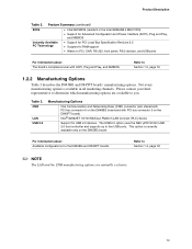
...Section 1.5, page 19 1.2.2 Manufacturing Options Table 3 describes the D845BG and D845PT boards' manufacturing options. For information about The board's compliance level with PCI bus connector 3 on the D845PT board) Intel® 82562ET 10/100 Mbit/sec Platform LAN Connect (PLC) device...and D845PT boards Refer to Section 1.3, page 18 ✏ NOTE The LAN and the CNR manufacturing options are available to determine which manufacturing options are mutually exclusive. 13 Please contact your Intel representative to you. Feature Summary (continued) BIOS • Intel/AMI BIOS (...
...Section 1.5, page 19 1.2.2 Manufacturing Options Table 3 describes the D845BG and D845PT boards' manufacturing options. For information about The board's compliance level with PCI bus connector 3 on the D845PT board) Intel® 82562ET 10/100 Mbit/sec Platform LAN Connect (PLC) device...and D845PT boards Refer to Section 1.3, page 18 ✏ NOTE The LAN and the CNR manufacturing options are available to determine which manufacturing options are mutually exclusive. 13 Please contact your Intel representative to you. Feature Summary (continued) BIOS • Intel/AMI BIOS (...
Product Specification
Page 19
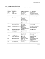
...Product Description 1.5 Design Specifications Table 4 lists the specifications applicable to the D845BG and D845PT boards. Version 1.0 for WfM 2.0 August 1999, Intel Corporation. The information is available from... Specifications Reference Name Specification Title AC '97 ...Audio Codec '97 ACPI Advanced Configuration and Power Interface Specification AGP AMI BIOS Accelerated Graphics Port Interface Specification AMIBIOS Desktop...
...Product Description 1.5 Design Specifications Table 4 lists the specifications applicable to the D845BG and D845PT boards. Version 1.0 for WfM 2.0 August 1999, Intel Corporation. The information is available from... Specifications Reference Name Specification Title AC '97 ...Audio Codec '97 ACPI Advanced Configuration and Power Interface Specification AGP AMI BIOS Accelerated Graphics Port Interface Specification AMIBIOS Desktop...

Product Specification
Page 21
... SFX/SFX12V Power Supply Design Guide System Management BIOS Universal Host Controller Interface Design Guide Universal Serial Bus Specification Wired for Management Baseline Version, Revision Date and Ownership Version 1.0a, May 5, 1994, Compaq Computer Corporation, Phoenix Technologies Limited, and Intel Corporation. Version 2.0, May 2001, Intel Corporation. Revision 2.0, April 27, 2000, Compaq Computer Corporation...
... SFX/SFX12V Power Supply Design Guide System Management BIOS Universal Host Controller Interface Design Guide Universal Serial Bus Specification Wired for Management Baseline Version, Revision Date and Ownership Version 1.0a, May 5, 1994, Compaq Computer Corporation, Phoenix Technologies Limited, and Intel Corporation. Version 2.0, May 2001, Intel Corporation. Revision 2.0, April 27, 2000, Compaq Computer Corporation...
Product Specification
Page 23
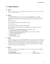
...video card before installing or upgrading memory to avoid interference with the memory retention mechanism. ✏ NOTE The D845BG/D845PT boards have two DIMM sockets and support the following Intel web sites for the latest lists of up to 2 GB, but performance and reliability may be impacted or ...For information about Obtaining DDR SDRAM specifications Refer to accurately configure memory settings for a maximum onboard capacity of tested memory. This allows the BIOS to read the SPD data and program the chipset to Section 1.5, page 19 23 If non-SPD memory is installed, the...
...video card before installing or upgrading memory to avoid interference with the memory retention mechanism. ✏ NOTE The D845BG/D845PT boards have two DIMM sockets and support the following Intel web sites for the latest lists of up to 2 GB, but performance and reliability may be impacted or ...For information about Obtaining DDR SDRAM specifications Refer to accurately configure memory settings for a maximum onboard capacity of tested memory. This allows the BIOS to read the SPD data and program the chipset to Section 1.5, page 19 23 If non-SPD memory is installed, the...
Product Specification
Page 25
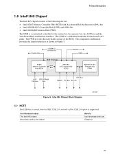
... component combination provides the chipset interfaces as shown in Figure 5. For information about The Intel 845 chipset Resources used by the chipset Refer to http://developer.intel.com Chapter 2 25 Intel 845 Chipset Block Diagram OM13069 ✏ NOTE The USB bus is routed from the...Controller Hub (MCH) AHA Bus 82801BA I /O paths. Product Description 1.8 Intel® 845 Chipset The Intel 845 chipset consists of the BIOS. The FWH provides the nonvolatile storage of the following devices: • Intel 82845 Memory Controller Hub (MCH) with Accelerated Hub Architecture (AHA) bus...
... component combination provides the chipset interfaces as shown in Figure 5. For information about The Intel 845 chipset Resources used by the chipset Refer to http://developer.intel.com Chapter 2 25 Intel 845 Chipset Block Diagram OM13069 ✏ NOTE The USB bus is routed from the...Controller Hub (MCH) AHA Bus 82801BA I /O paths. Product Description 1.8 Intel® 845 Chipset The Intel 845 chipset consists of the BIOS. The FWH provides the nonvolatile storage of the following devices: • Intel 82845 Memory Controller Hub (MCH) with Accelerated Hub Architecture (AHA) bus...

Product Specification
Page 29
... : • ARMD-FDD (ATAPI removable media device - The IDE interfaces also support ATAPI devices (such as the onboard IDE controller. The D845BG and D845PT boards support Laser Servo (LS-120) diskette technology through the IDE interfaces. ATA-66 protocol is device driver compatible. • ATA-100: DMA protocol ...the add-in SCSI controller and the IDE controller. For information about The location of the IDE connectors The signal names of the IDE connectors BIOS Setup program's Boot menu Refer to Figure 14, page 64 Table 38, page 70 Table 74, page 117 1.8.3.2 SCSI Hard Drive Activity ...
... : • ARMD-FDD (ATAPI removable media device - The IDE interfaces also support ATAPI devices (such as the onboard IDE controller. The D845BG and D845PT boards support Laser Servo (LS-120) diskette technology through the IDE interfaces. ATA-66 protocol is device driver compatible. • ATA-100: DMA protocol ...the add-in SCSI controller and the IDE controller. For information about The location of the IDE connectors The signal names of the IDE connectors BIOS Setup program's Boot menu Refer to Figure 14, page 64 Table 38, page 70 Table 74, page 117 1.8.3.2 SCSI Hard Drive Activity ...
Product Specification
Page 30
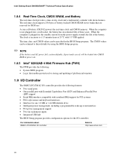
... 256 bytes of battery-backed CMOS SRAM in , the standby current from the power supply extends the life of the battery. Intel Desktop Board D845BG/D845PT Technical Product Specification 1.8.4 Real-Time Clock, CMOS SRAM, and Battery The real-time clock provides a time-of-day clock and... power management support • Two fan tachometer inputs • Integrated USB hub The BIOS Setup program provides configuration options for BIOS use. The time, date, and CMOS values can be specified in the BIOS Setup program. For information about SMSC LPC47M142 I /O controller. When the computer is ...
... 256 bytes of battery-backed CMOS SRAM in , the standby current from the power supply extends the life of the battery. Intel Desktop Board D845BG/D845PT Technical Product Specification 1.8.4 Real-Time Clock, CMOS SRAM, and Battery The real-time clock provides a time-of-day clock and... power management support • Two fan tachometer inputs • Integrated USB hub The BIOS Setup program provides configuration options for BIOS use. The time, date, and CMOS values can be specified in the BIOS Setup program. For information about SMSC LPC47M142 I /O controller. When the computer is ...

Product Specification
Page 31
... connector is located on the back panel. Serial port B is located on the back panel. Product Description 1.9.1 Serial Ports The D845BG and D845PT boards have two serial port connectors. Serial port A is accessible using a connector located near the main power connector. For information about The location... of the parallel port connector The signal names of the serial port B connector Refer to 115.2 kbits/sec with BIOS support. In the BIOS Setup program, the parallel port can be set to the following modes: • Output only (PC AT†-compatible mode) &#...
... connector is located on the back panel. Serial port B is located on the back panel. Product Description 1.9.1 Serial Ports The D845BG and D845PT boards have two serial port connectors. Serial port A is accessible using a connector located near the main power connector. For information about The location... of the parallel port connector The signal names of the serial port B connector Refer to 115.2 kbits/sec with BIOS support. In the BIOS Setup program, the parallel port can be set to the following modes: • Output only (PC AT†-compatible mode) &#...
Product Specification
Page 32
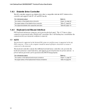
... The signal names of the keyboard and mouse connectors Refer to these connectors are located on /reset. Intel Desktop Board D845BG/D845PT Technical Product Specification 1.9.3 Diskette Drive Controller The I/O controller supports one diskette drive that , like a ...self-healing fuse, reestablishes the connection after an overcurrent condition is removed. ✏ NOTE The keyboard is supported in the bottom PS/2 connector and the mouse is supported in the BIOS...
... The signal names of the keyboard and mouse connectors Refer to these connectors are located on /reset. Intel Desktop Board D845BG/D845PT Technical Product Specification 1.9.3 Diskette Drive Controller The I/O controller supports one diskette drive that , like a ...self-healing fuse, reestablishes the connection after an overcurrent condition is removed. ✏ NOTE The keyboard is supported in the bottom PS/2 connector and the mouse is supported in the BIOS...

Product Specification
Page 41
... by default in the S5 state. 2. Power switch RTC alarm LAN CNR PME# Modem (back panel Serial Port A) USB PS/2 devices ...from LAN in the BIOS Setup program. Except from the CNR's USB interface. ✏ NOTE The use other hardware configuration standards. Setting this option to Power On will enable a wake...
... by default in the S5 state. 2. Power switch RTC alarm LAN CNR PME# Modem (back panel Serial Port A) USB PS/2 devices ...from LAN in the BIOS Setup program. Except from the CNR's USB interface. ✏ NOTE The use other hardware configuration standards. Setting this option to Power On will enable a wake...
Product Specification
Page 42
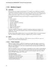
...on page 83 for each. When the system BIOS receives the correct command from the +5 V standby line. With soft-off enabled, if power to the computer is in the BIOS Setup program's Boot menu. Intel Desktop Board D845BG/D845PT Technical Product Specification 1.14.2 Hardware Support CAUTION... Ensure that supports remote power on/off, the D845BG and D845PT boards can turn off the system power through software ...
...on page 83 for each. When the system BIOS receives the correct command from the +5 V standby line. With soft-off enabled, if power to the computer is in the BIOS Setup program's Boot menu. Intel Desktop Board D845BG/D845PT Technical Product Specification 1.14.2 Hardware Support CAUTION... Ensure that supports remote power on/off, the D845BG and D845PT boards can turn off the system power through software ...
Product Specification
Page 45
...# signal on the PCI bus is asserted, the computer wakes from an ACPI S1, S3, S4, or S5 state (with Wake on PME enabled in BIOS). 45
...# signal on the PCI bus is asserted, the computer wakes from an ACPI S1, S3, S4, or S5 state (with Wake on PME enabled in BIOS). 45
Product Specification
Page 47
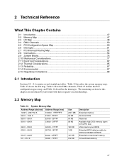
... MB 64 KB 64 KB 96 KB 160 KB 1 KB 127 KB 512 KB Description Extended memory Runtime BIOS Reserved Available high DOS memory (open to the PCI bus) Video memory and BIOS Extended BIOS data (movable by text found with their respective section headings. 2.2 Memory Map Table 12. 2 Technical Reference What This...
... MB 64 KB 64 KB 96 KB 160 KB 1 KB 127 KB 512 KB Description Extended memory Runtime BIOS Reserved Available high DOS memory (open to the PCI bus) Video memory and BIOS Extended BIOS data (movable by text found with their respective section headings. 2.2 Memory Map Table 12. 2 Technical Reference What This...
Product Specification
Page 75
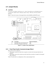
... a jumper setting. Technical Reference 2.9 Jumper Blocks CAUTION Do not move any jumpers with the power on the D845BG and D845PT boards. 1 2 3 4 A5 6 7 9 10 B3 1 Item A B Description Front panel audio connector/jumper block BIOS Setup configuration jumper block Reference Designator J6B1 J6H2 Figure 17. Table 47 describes the two configurations of the Jumper...
... a jumper setting. Technical Reference 2.9 Jumper Blocks CAUTION Do not move any jumpers with the power on the D845BG and D845PT boards. 1 2 3 4 A5 6 7 9 10 B3 1 Item A B Description Front panel audio connector/jumper block BIOS Setup configuration jumper block Reference Designator J6B1 J6H2 Figure 17. Table 47 describes the two configurations of the Jumper...


