

Product Specification
Page 29
...program's Boot menu to reduce reflections, noise, and inductive coupling. The D845BG and D845PT boards support Laser Servo (LS-120) diskette technology through the IDE interfaces. The LED indicates when data is a 1 x 2-pin connector that can achieve read from, or written to the BIOS. For information about... • Programmed I/O (PIO): processor controls data transfer. • 8237-style DMA: DMA offloads the processor, supporting transfer rates of up to 16 MB/sec. • Ultra DMA: DMA protocol on IDE bus supporting host and target throttling and transfer rates of up to 33 MB/sec....
...program's Boot menu to reduce reflections, noise, and inductive coupling. The D845BG and D845PT boards support Laser Servo (LS-120) diskette technology through the IDE interfaces. The LED indicates when data is a 1 x 2-pin connector that can achieve read from, or written to the BIOS. For information about... • Programmed I/O (PIO): processor controls data transfer. • 8237-style DMA: DMA offloads the processor, supporting transfer rates of up to 16 MB/sec. • Ultra DMA: DMA protocol on IDE bus supporting host and target throttling and transfer rates of up to 33 MB/sec....

Product Specification
Page 31
... connector The signal names of the serial port B connector Refer to Figure 11, page 55 Table 21, page 57 Figure 16, page 71 Table 41, page 72 1.9.2 Parallel Port The 25-pin D-Sub parallel port connector is accessible using a connector located near the main power connector. In the BIOS Setup program, the... BIOS support. The serial ports can be assigned as COM1 (3F8h), COM2 (2F8h), COM3 (3E8h), or COM4 (2E8h). Product Description 1.9.1 Serial Ports The D845BG and D845PT boards have two serial port connectors. Serial port A is located on the back panel.
... connector The signal names of the serial port B connector Refer to Figure 11, page 55 Table 21, page 57 Figure 16, page 71 Table 41, page 72 1.9.2 Parallel Port The 25-pin D-Sub parallel port connector is accessible using a connector located near the main power connector. In the BIOS Setup program, the... BIOS support. The serial ports can be assigned as COM1 (3F8h), COM2 (2F8h), COM3 (3E8h), or COM4 (2E8h). Product Description 1.9.1 Serial Ports The D845BG and D845PT boards have two serial port connectors. Serial port A is located on the back panel.

Product Specification
Page 56
... Name 1 Data 2 Not connected 3 Ground 4 +5 V (Fused) 5 Clock 6 Not connected Table 19. USB Connectors Pin Signal Name 1 +5 V (Fused) 2 USB# 3 USB 4 Ground Table 20. Parallel Port Connector Pin 1 2 3 4 5 6 7 8 9 10 11 12 13 14 15 16 17 18 - 25 Standard Signal Name STROBE# PD0 PD1 PD2 PD3 PD4 PD5 PD6 PD7 ACK# BUSY PERROR SELECT AUDOFD...#, REVERSERQST# SLCTIN# Ground EPP Signal Name WRITE# PD0 PD1 PD2 PD3 PD4 PD5 PD6 PD7 INTR WAIT# PE SELECT DATASTB# FAULT# RESET# ADDRSTB# Ground 56 Intel Desktop Board D845BG/D845PT Technical Product Specification Table 18.
... Name 1 Data 2 Not connected 3 Ground 4 +5 V (Fused) 5 Clock 6 Not connected Table 19. USB Connectors Pin Signal Name 1 +5 V (Fused) 2 USB# 3 USB 4 Ground Table 20. Parallel Port Connector Pin 1 2 3 4 5 6 7 8 9 10 11 12 13 14 15 16 17 18 - 25 Standard Signal Name STROBE# PD0 PD1 PD2 PD3 PD4 PD5 PD6 PD7 ACK# BUSY PERROR SELECT AUDOFD...#, REVERSERQST# SLCTIN# Ground EPP Signal Name WRITE# PD0 PD1 PD2 PD3 PD4 PD5 PD6 PD7 INTR WAIT# PE SELECT DATASTB# FAULT# RESET# ADDRSTB# Ground 56 Intel Desktop Board D845BG/D845PT Technical Product Specification Table 18.

Product Specification
Page 63
Technical Reference Table 31. Main Power Connector Pin Signal Name Pin 1 +3.3 V 11 2 +3.3 V 12 3 Ground 13 4 +5 V 14 5 Ground 15 6 +5 V 16 7 Ground 17 8 PWRGD (Power Good) 18 9 +5 V (Standby) 19 10 +12 V 20 Table 32. Chassis Intrusion Connector Pin Signal Name 1 Intruder 2 Ground Signal Name +3.3 V -12 V Ground PS-ON# (power supply remote on/off) Ground Ground Ground No connect +5 V +5 V 63 Front Chassis Fan Connector Pin Signal Name 1 Ground 2 +12 V 3 No connect Table 33.
Technical Reference Table 31. Main Power Connector Pin Signal Name Pin 1 +3.3 V 11 2 +3.3 V 12 3 Ground 13 4 +5 V 14 5 Ground 15 6 +5 V 16 7 Ground 17 8 PWRGD (Power Good) 18 9 +5 V (Standby) 19 10 +12 V 20 Table 32. Chassis Intrusion Connector Pin Signal Name 1 Intruder 2 Ground Signal Name +3.3 V -12 V Ground PS-ON# (power supply remote on/off) Ground Ground Ground No connect +5 V +5 V 63 Front Chassis Fan Connector Pin Signal Name 1 Ground 2 +12 V 3 No connect Table 33.

Product Specification
Page 69
... Ground 23 Ground 25 Ground 27 Not connected 29 Ground 31 Ground 33 Ground Technical Reference Pin Signal Name 2 DENSEL 4 Not connected 6 DRVDEN1 8 FDINDX# 10 MTR0# (Motor Enable A) 12 Not connected 14 DS0# (Drive Select A) 16 Not connected 18 DIR# (Stepper Motor Direction) 20 STEP# (Step Pulse) 22 WDATA# (Write Data) 24...
... Ground 23 Ground 25 Ground 27 Not connected 29 Ground 31 Ground 33 Ground Technical Reference Pin Signal Name 2 DENSEL 4 Not connected 6 DRVDEN1 8 FDINDX# 10 MTR0# (Motor Enable A) 12 Not connected 14 DS0# (Drive Select A) 16 Not connected 18 DIR# (Stepper Motor Direction) 20 STEP# (Step Pulse) 22 WDATA# (Write Data) 24...

Product Specification
Page 70
Table 39. PCI IDE Connectors Pin Signal Name Pin 1 Reset IDE 2 3 Data 7 4 5 Data 6 6 7 Data 5 8 9 Data 4 10 11 Data 3 12 13 Data 2 14 15 Data 1 16 17 Data 0 18 19 Ground 20 21 DDRQ0 [DDRQ1] 22 23 I/O Write# 24 25 I/O Read# 26 27 IOCHRDY 28 29 DDACK0# [DDACK1#]...37 Chip Select 1P# [Chip Select 1S#] 38 39 Activity# 40 Signal names in brackets ([ ]) are for the secondary IDE connector. SCSI LED Connector Pin Signal Name 1 SCSI_ACT# 2 No connect Signal Name Ground Data 8 Data 9 Data 10 Data 11 Data 12 Data 13 Data 14 Data 15 Key Ground...
Table 39. PCI IDE Connectors Pin Signal Name Pin 1 Reset IDE 2 3 Data 7 4 5 Data 6 6 7 Data 5 8 9 Data 4 10 11 Data 3 12 13 Data 2 14 15 Data 1 16 17 Data 0 18 19 Ground 20 21 DDRQ0 [DDRQ1] 22 23 I/O Write# 24 25 I/O Read# 26 27 IOCHRDY 28 29 DDACK0# [DDACK1#]...37 Chip Select 1P# [Chip Select 1S#] 38 39 Activity# 40 Signal names in brackets ([ ]) are for the secondary IDE connector. SCSI LED Connector Pin Signal Name 1 SCSI_ACT# 2 No connect Signal Name Ground Data 8 Data 9 Data 10 Data 11 Data 12 Data 13 Data 14 Data 15 Key Ground...
Product Specification
Page 73
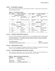
... Ground 14 15 N/C No connect 16 Signal In/Out Description Power LED HDR_BLNK_ Out GRN Front panel green LED HDR_BLNK_ Out YEL Front panel yellow LED On/Off Switch FPBUT_IN In Power switch Ground Ground Miscellaneous N/C Not connected Ground Ground (pin removed) Not connected +5 V Out... 7 can be connected to a momentary SPST type switch that data is closed, the D845BG/D845PT board resets and runs the POST. 2.8.3.2.3 Power/Sleep/Message Waiting LED Connector Pins 2 and 4 can be connected to a hard drive. States for a two-color LED. Table 46 shows the possible ...
... Ground 14 15 N/C No connect 16 Signal In/Out Description Power LED HDR_BLNK_ Out GRN Front panel green LED HDR_BLNK_ Out YEL Front panel yellow LED On/Off Switch FPBUT_IN In Power switch Ground Ground Miscellaneous N/C Not connected Ground Ground (pin removed) Not connected +5 V Out... 7 can be connected to a momentary SPST type switch that data is closed, the D845BG/D845PT board resets and runs the POST. 2.8.3.2.3 Power/Sleep/Message Waiting LED Connector Pins 2 and 4 can be connected to a hard drive. States for a two-color LED. Table 46 shows the possible ...
Intel Desktop Board D845PT/D845BG Product Guide
Page 73
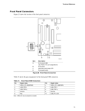
... name 1 VREG_FP_WSBPWR0 3 USB_FPP0- 5 USB_FPP0+ 7 Ground 9 Key Note: USB ports may be assigned as needed. Front Panel Connectors Table 31 shows the pin assignments for pin assignments) Front panel Alternate power/sleep LED Front panel audio Figure 25. Front Panel Connectors Figure 25 shows the location of the front panel connectors. ...
... name 1 VREG_FP_WSBPWR0 3 USB_FPP0- 5 USB_FPP0+ 7 Ground 9 Key Note: USB ports may be assigned as needed. Front Panel Connectors Table 31 shows the pin assignments for pin assignments) Front panel Alternate power/sleep LED Front panel audio Figure 25. Front Panel Connectors Figure 25 shows the location of the front panel connectors. ...

Quick Reference Guide
Page 4
Desktop Board Components D845PT Board Components Line In USB Devices A BCD USB Devices AA E F Z G Y H X I W J K V U T SR Q P O NM L 16 15 +5V Ground On No Connection Reset 3 1 2-pin alternate power/sleep LED connector Power LED 2 1 HD LED OM12642 continued 4 Intel Desktop Boards D845PT and D845BG Quick Reference
Desktop Board Components D845PT Board Components Line In USB Devices A BCD USB Devices AA E F Z G Y H X I W J K V U T SR Q P O NM L 16 15 +5V Ground On No Connection Reset 3 1 2-pin alternate power/sleep LED connector Power LED 2 1 HD LED OM12642 continued 4 Intel Desktop Boards D845PT and D845BG Quick Reference

Quick Reference Guide
Page 6
D845BG Board Components Line In AA Z Y X W V On USB Devices A BCD USB Devices E F G H I J K U TSRQ P O N M L +5V Ground 16 15 No Connection Power LED 2 1 Reset HD LED 3 1 2-pin alternate power/sleep LED connector OM12643 continued 6 Intel Desktop Boards D845PT and D845BG Quick Reference
D845BG Board Components Line In AA Z Y X W V On USB Devices A BCD USB Devices E F G H I J K U TSRQ P O N M L +5V Ground 16 15 No Connection Power LED 2 1 Reset HD LED 3 1 2-pin alternate power/sleep LED connector OM12643 continued 6 Intel Desktop Boards D845PT and D845BG Quick Reference

Quick Reference Guide
Page 24
D845PT Line In USB Devices A BCD USB Devices AA E F Z G Y H X I W J K V U T SR Q P O NM L 16 15 +5V Ground 3 1 No Connection 2-pin alternate power/sleep LED connector On Reset Power LED 2 1 HD LED OM12642 4 Intel D845PT D845BG
D845PT Line In USB Devices A BCD USB Devices AA E F Z G Y H X I W J K V U T SR Q P O NM L 16 15 +5V Ground 3 1 No Connection 2-pin alternate power/sleep LED connector On Reset Power LED 2 1 HD LED OM12642 4 Intel D845PT D845BG

Quick Reference Guide
Page 26
D845BG Line In AA Z Y X W V On USB Devices A BCD USB Devices E F G H I J K U TSRQ P O N M L 16 15 +5V Ground No Connection Power LED 2 1 Reset HD LED 3 1 2-pin alternate power/sleep LED connector OM12643 6 Intel D845PT D845BG
D845BG Line In AA Z Y X W V On USB Devices A BCD USB Devices E F G H I J K U TSRQ P O N M L 16 15 +5V Ground No Connection Power LED 2 1 Reset HD LED 3 1 2-pin alternate power/sleep LED connector OM12643 6 Intel D845PT D845BG


