
Product Specification
Page 5
... 1.9 I/O Controller ...30 1.9.1 Serial Ports 31 1.9.2 Parallel Port 31 1.9.3 Diskette Drive Controller 32 1.9.4 Keyboard and Mouse Interface 32 1.10 Audio Subsystem...33 1.10.1 Audio Connectors 34 1.10.2 Audio Subsystem Software 34 1.11 LAN Subsystem (Optional 35 1.11.1 Intel® 82562ET Platform LAN Connect Device 35 1.11.2 RJ-45 LAN Connector with Integrated LEDs 35 1.11...
... 1.9 I/O Controller ...30 1.9.1 Serial Ports 31 1.9.2 Parallel Port 31 1.9.3 Diskette Drive Controller 32 1.9.4 Keyboard and Mouse Interface 32 1.10 Audio Subsystem...33 1.10.1 Audio Connectors 34 1.10.2 Audio Subsystem Software 34 1.11 LAN Subsystem (Optional 35 1.11.1 Intel® 82562ET Platform LAN Connect Device 35 1.11.2 RJ-45 LAN Connector with Integrated LEDs 35 1.11...
Product Specification
Page 6
Intel Desktop Board D845BG/D845PT Technical Product Specification 2 Technical Reference 2.1 Introduction...47 2.2 Memory Map ...47 2.3 I/O Map ...48 2.4 DMA Channels ...50 2.5 PCI Configuration Space Map 50 2.6 Interrupts ... I/O Connectors 71 2.9 Jumper Blocks...75 2.9.1 Front Panel Audio Connector/Jumper Block 75 2.9.2 BIOS Setup Configuration Jumper Block 76 2.10 Mechanical Considerations 77 2.10.1 D845BG Form Factor 77 2.10.2 D845PT Form Factor 78 2.10.3 I/O Shield ...79 2.11 Electrical Considerations 82 2.11.1 Power Consumption 82 2.11.2 Add-in Board Considerations 82 2.11.3 ...
Intel Desktop Board D845BG/D845PT Technical Product Specification 2 Technical Reference 2.1 Introduction...47 2.2 Memory Map ...47 2.3 I/O Map ...48 2.4 DMA Channels ...50 2.5 PCI Configuration Space Map 50 2.6 Interrupts ... I/O Connectors 71 2.9 Jumper Blocks...75 2.9.1 Front Panel Audio Connector/Jumper Block 75 2.9.2 BIOS Setup Configuration Jumper Block 76 2.10 Mechanical Considerations 77 2.10.1 D845BG Form Factor 77 2.10.2 D845PT Form Factor 78 2.10.3 I/O Shield ...79 2.11 Electrical Considerations 82 2.11.1 Power Consumption 82 2.11.2 Add-in Board Considerations 82 2.11.3 ...
Product Specification
Page 7
...; Rapid BIOS Boot 96 3.9.1 Peripheral Selection and Configuration 96 3.9.2 Intel Rapid BIOS Boot 97 3.10 BIOS Security Features 98 4 BIOS Setup Program 4.1 Introduction...99 4.2 Maintenance Menu 100 4.2.1 Extended Configuration Submenu 101 4.3 Main Menu...102 ...3.8 Boot Options...96 3.8.1 CD-ROM and Network Boot 96 3.8.2 Booting Without Attached Devices 96 3.9 Fast Booting Systems with Optional USB 2.0 Support 17 5. D845PT Board Components 15 3. USB 1.1 Port Configuration 27 7. USB 2.0 Port Configuration (Optional 28 8. Audio Subsystem Block Diagram 33 9. ICH2 and CNR Signal ...
...; Rapid BIOS Boot 96 3.9.1 Peripheral Selection and Configuration 96 3.9.2 Intel Rapid BIOS Boot 97 3.10 BIOS Security Features 98 4 BIOS Setup Program 4.1 Introduction...99 4.2 Maintenance Menu 100 4.2.1 Extended Configuration Submenu 101 4.3 Main Menu...102 ...3.8 Boot Options...96 3.8.1 CD-ROM and Network Boot 96 3.8.2 Booting Without Attached Devices 96 3.9 Fast Booting Systems with Optional USB 2.0 Support 17 5. D845PT Board Components 15 3. USB 1.1 Port Configuration 27 7. USB 2.0 Port Configuration (Optional 28 8. Audio Subsystem Block Diagram 33 9. ICH2 and CNR Signal ...
Product Specification
Page 8
Power and Hardware Control Connectors 61 14. D845PT Add-in Board and Peripheral Interface Connectors 64 15. D845PT Board Dimensions 78 20. Localized High Temperature Zones 86 Tables 1. Supported Processors 22 6. LAN Connector LED States 35 8. Wake-up Devices and Events 41 11. ... with USB 2.0) ....81 23. Effects of Board Differences 11 2. I/O Map ...48 14. PCI Interrupt Routing Map 53 18. Power States and Targeted System Power 40 10. Fan Connector Function/Operation 43 12. Audio Line Out Connector 57 25. Rear Chassis Fan Connector 62 30. Mic In Connector ...57 26...
Power and Hardware Control Connectors 61 14. D845PT Add-in Board and Peripheral Interface Connectors 64 15. D845PT Board Dimensions 78 20. Localized High Temperature Zones 86 Tables 1. Supported Processors 22 6. LAN Connector LED States 35 8. Wake-up Devices and Events 41 11. ... with USB 2.0) ....81 23. Effects of Board Differences 11 2. I/O Map ...48 14. PCI Interrupt Routing Map 53 18. Power States and Targeted System Power 40 10. Fan Connector Function/Operation 43 12. Audio Line Out Connector 57 25. Rear Chassis Fan Connector 62 30. Mic In Connector ...57 26...
Product Specification
Page 11
...2.0 host controller have only five PCI bus connectors. ✏ NOTE Most of the items listed in this document show only the D845PT board. 1 Product Description What This Chapter Contains 1.1 Board Differences...11 1.2 Overview ...12 1.3 Online Support ...18 1.4 Operating System... Support 18 1.5 Design Specifications 19 1.6 Processor ...22 1.7 System Memory ...23 1.8 Intel® 845 Chipset...25 1.9 I/O Controller ...30 1.10 Audio Subsystem...33 1.11 LAN Subsystem (Optional 35 1.12 CNR (Optional) ...36 1.13 Hardware Management Subsystem 37 1....
...2.0 host controller have only five PCI bus connectors. ✏ NOTE Most of the items listed in this document show only the D845PT board. 1 Product Description What This Chapter Contains 1.1 Board Differences...11 1.2 Overview ...12 1.3 Online Support ...18 1.4 Operating System... Support 18 1.5 Design Specifications 19 1.6 Processor ...22 1.7 System Memory ...23 1.8 Intel® 845 Chipset...25 1.9 I/O Controller ...30 1.10 Audio Subsystem...33 1.11 LAN Subsystem (Optional 35 1.12 CNR (Optional) ...36 1.13 Hardware Management Subsystem 37 1....
Product Specification
Page 13
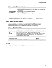
... Section 1.5, page 19 1.2.2 Manufacturing Options Table 3 describes the D845BG and D845PT boards' manufacturing options. For information about Available configurations for PCI Local Bus... Refer to five USB ports. This option is available in the Intel 82802AB 4 Mbit FWH) • Support for Advanced Configuration and ... Available PC Technology • Support for the D845BG and D845PT boards Refer to Section 1.3, page 18 ✏ NOTE ...exclusive. 13 Please contact your Intel representative to you. Feature Summary (continued) BIOS • Intel/AMI BIOS (resident in all...
... Section 1.5, page 19 1.2.2 Manufacturing Options Table 3 describes the D845BG and D845PT boards' manufacturing options. For information about Available configurations for PCI Local Bus... Refer to five USB ports. This option is available in the Intel 82802AB 4 Mbit FWH) • Support for Advanced Configuration and ... Available PC Technology • Support for the D845BG and D845PT boards Refer to Section 1.3, page 18 ✏ NOTE ...exclusive. 13 Please contact your Intel representative to you. Feature Summary (continued) BIOS • Intel/AMI BIOS (resident in all...
Product Specification
Page 20
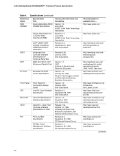
...usb.org/ developers/docs.html http://www.pcisig.com/ specifications http://www.pcisig.com/ specifications continued 20 Intel Desktop Board D845BG/D845PT Technical Product Specification Table 4. Specifications (continued) Reference Name DDR SDRAM EHCI EPP El Torito Front Panel ...I/O Connectivity Design Guide Low Pin Count Interface Specification microATX Motherboard Interface Specification OpenHCI - Release 1.0a, October 10, 1996, Compaq Computer Corp., Microsoft Corporation, and National Semiconductor Corp. Version 1.0, January 25, 1995, Phoenix Technologies Limited and...
...usb.org/ developers/docs.html http://www.pcisig.com/ specifications http://www.pcisig.com/ specifications continued 20 Intel Desktop Board D845BG/D845PT Technical Product Specification Table 4. Specifications (continued) Reference Name DDR SDRAM EHCI EPP El Torito Front Panel ...I/O Connectivity Design Guide Low Pin Count Interface Specification microATX Motherboard Interface Specification OpenHCI - Release 1.0a, October 10, 1996, Compaq Computer Corp., Microsoft Corporation, and National Semiconductor Corp. Version 1.0, January 25, 1995, Phoenix Technologies Limited and...
Product Specification
Page 33
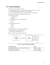
Product Description 1.10 Audio Subsystem The audio subsystem includes these features: • Split digital/analog architecture for : Line out Mic in • Back panel audio connectors: &#... The audio subsystem supports the following audio interfaces: • ATAPI-style connectors: Auxiliary line in The audio subsystem consists of the following devices: • Intel 82801BA I/O Controller Hub (ICH2) • Analog Devices AD1885 audio codec Figure 8 is a block diagram of the audio subsystem. 82801BA I/O Controller Hub (ICH2) AC '97 Link...
Product Description 1.10 Audio Subsystem The audio subsystem includes these features: • Split digital/analog architecture for : Line out Mic in • Back panel audio connectors: &#... The audio subsystem supports the following audio interfaces: • ATAPI-style connectors: Auxiliary line in The audio subsystem consists of the following devices: • Intel 82801BA I/O Controller Hub (ICH2) • Analog Devices AD1885 audio codec Figure 8 is a block diagram of the audio subsystem. 82801BA I/O Controller Hub (ICH2) AC '97 Link...
Product Specification
Page 34
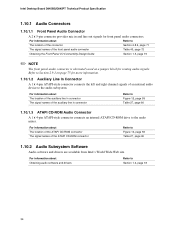
... of the ATAPI CD-ROM connector Refer to Figure 12, page 59 Table 27, page 60 1.10.2 Audio Subsystem Software Audio software and drivers are available from Intel's World Wide Web site. For information about Refer to The location of the connector Section 2.8.3, page...and line out signals for front panel audio connectors. Refer to Section 2.9.1 on page 75 for routing audio signals. Intel Desktop Board D845BG/D845PT Technical Product Specification 1.10.1 Audio Connectors 1.10.1.1 Front Panel Audio Connector A 2 x 5-pin connector provides mic in connector Refer to Figure 12, page 59 ...
... of the ATAPI CD-ROM connector Refer to Figure 12, page 59 Table 27, page 60 1.10.2 Audio Subsystem Software Audio software and drivers are available from Intel's World Wide Web site. For information about Refer to The location of the connector Section 2.8.3, page...and line out signals for front panel audio connectors. Refer to Section 2.9.1 on page 75 for routing audio signals. Intel Desktop Board D845BG/D845PT Technical Product Specification 1.10.1 Audio Connectors 1.10.1.1 Front Panel Audio Connector A 2 x 5-pin connector provides mic in connector Refer to Figure 12, page 59 ...

Product Specification
Page 35
... is operating. Yellow Off LAN link is established. On (brighter and pulsing) The computer is selected. The Intel 82562ET provides the following functions: • Basic 10/100 Ethernet LAN connectivity • Supports RJ-45 connector with integrated LEDs. Table 7. On (steady state) ... device driver compatibility • ACPI support • Programmable transit threshold • Configuration EEPROM that supports the 82562ET (10/100 Mbit/sec Ethernet) on the CNR bus • PCI Power Management Supports ACPI technology Supports LAN wake capabilities...
... is operating. Yellow Off LAN link is established. On (brighter and pulsing) The computer is selected. The Intel 82562ET provides the following functions: • Basic 10/100 Ethernet LAN connectivity • Supports RJ-45 connector with integrated LEDs. Table 7. On (steady state) ... device driver compatibility • ACPI support • Programmable transit threshold • Configuration EEPROM that supports the 82562ET (10/100 Mbit/sec Ethernet) on the CNR bus • PCI Power Management Supports ACPI technology Supports LAN wake capabilities...

Product Specification
Page 38
...on Ring Wake from USB Wake from PS/2 devices Power Management Event (PME#) wake-up events (see Table 10 on page 41) • Support for multiple wake-up support 1.14.1 ACPI ACPI gives the operating system direct control over the power management... detection may require an ACPI-aware driver), video displays, and hard disk drives • Methods for normal computer operation. Intel Desktop Board D845BG/D845PT Technical Product Specification 1.13.3 Chassis Intrusion and Detection The boards support a chassis security feature that provides full ACPI support.
...on Ring Wake from USB Wake from PS/2 devices Power Management Event (PME#) wake-up events (see Table 10 on page 41) • Support for multiple wake-up support 1.14.1 ACPI ACPI gives the operating system direct control over the power management... detection may require an ACPI-aware driver), video displays, and hard disk drives • Methods for normal computer operation. Intel Desktop Board D845BG/D845PT Technical Product Specification 1.13.3 Chassis Intrusion and Detection The boards support a chassis security feature that provides full ACPI support.

Product Specification
Page 41
... information so that can wake the computer from this option to configure devices that do not use of these wake-up Devices and Events Table 10 lists the devices or specific events that operating systems can wake up event from LAN in the BIOS Setup program. ACPI is disabled by ACPI..., S4, S5 S1, S3, S4, S5 (Note 1) S1, S3, S4 (Note 2), S5 (Note 2) S1, S3, S4, S5 S1, S3 S1, S3 S1, S3 Notes: 1. Table 10.
... information so that can wake the computer from this option to configure devices that do not use of these wake-up Devices and Events Table 10 lists the devices or specific events that operating systems can wake up event from LAN in the BIOS Setup program. ACPI is disabled by ACPI..., S4, S5 S1, S3, S4, S5 (Note 1) S1, S3, S4 (Note 2), S5 (Note 2) S1, S3, S4, S5 S1, S3 S1, S3 S1, S3 Notes: 1. Table 10.
Product Specification
Page 44
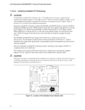
...and any devices connected to provide adequate standby current when implementing Instantly Available PC technology can damage the power supply. Intel Desktop Board D845BG/D845PT Technical Product Specification 1.14.2.4 Instantly Available PC Technology CAUTION For Instantly Available PC technology, the +5 V standby ... or event, the system quickly returns to wake the computer. Add-in cards and drivers. Failure to the board. Figure 10 shows the location of providing adequate +5 V standby current. Location of Instantly Available PC technology requires operating system support and PCI...
...and any devices connected to provide adequate standby current when implementing Instantly Available PC technology can damage the power supply. Intel Desktop Board D845BG/D845PT Technical Product Specification 1.14.2.4 Instantly Available PC Technology CAUTION For Instantly Available PC technology, the +5 V standby ... or event, the system quickly returns to wake the computer. Add-in cards and drivers. Failure to the board. Figure 10 shows the location of providing adequate +5 V standby current. Location of Instantly Available PC technology requires operating system support and PCI...
Product Specification
Page 47
... 13 shows the I /O Map ...48 2.4 DMA Channels ...50 2.5 PCI Configuration Space Map 50 2.6 Interrupts ...51 2.7 PCI Interrupt Routing Map 52 2.8 Connectors ...54 2.9 Jumper Blocks...75 2.10 Mechanical Considerations 77 2.11 Electrical Considerations 82 2.12 Thermal Considerations 85 2.13 Reliability ...87 2.14 Environmental ...87 2.15 Regulatory Compliance 88 2.1 Introduction Sections 2.2 - 2.6 contain several...
... 13 shows the I /O Map ...48 2.4 DMA Channels ...50 2.5 PCI Configuration Space Map 50 2.6 Interrupts ...51 2.7 PCI Interrupt Routing Map 52 2.8 Connectors ...54 2.9 Jumper Blocks...75 2.10 Mechanical Considerations 77 2.11 Electrical Considerations 82 2.12 Thermal Considerations 85 2.13 Reliability ...87 2.14 Environmental ...87 2.15 Regulatory Compliance 88 2.1 Introduction Sections 2.2 - 2.6 contain several...

Product Specification
Page 51
... PIC 3 COM2 (Note 1) 4 COM1 (Note 1) 5 LPT2 (Plug and Play option)/User available 6 Diskette drive 7 LPT1 (Note 1) 8 Real-time clock 9 Reserved for ICH2 system management bus 10 User available 11 User available 12 Onboard mouse port (if present, else user available) 13 Reserved, math coprocessor 14 15 16 (Note 2) 17 (Note 2) 18...
... PIC 3 COM2 (Note 1) 4 COM1 (Note 1) 5 LPT2 (Plug and Play option)/User available 6 Diskette drive 7 LPT1 (Note 1) 8 Real-time clock 9 Reserved for ICH2 system management bus 10 User available 11 User available 12 Onboard mouse port (if present, else user available) 13 Reserved, math coprocessor 14 15 16 (Note 2) 17 (Note 2) 18...

Product Specification
Page 53
... have a unique interrupt. However, in APIC mode. 53 Refer to Table 16 for two or more of PIRQ lines to one of the IRQ signals (3, 4, 5, 6, 7, 9, 10, 11, 12, 14, and 15). D845BG board only PIRQF INTB INTA INTD INTC INTB INTA INTB ICH2 PIRQ Signal Name PIRQG PIRQH PIRQB Other INTB...
... have a unique interrupt. However, in APIC mode. 53 Refer to Table 16 for two or more of PIRQ lines to one of the IRQ signals (3, 4, 5, 6, 7, 9, 10, 11, 12, 14, and 15). D845BG board only PIRQF INTB INTA INTD INTC INTB INTA INTB ICH2 PIRQ Signal Name PIRQG PIRQH PIRQB Other INTB...

Product Specification
Page 56
Intel Desktop Board D845BG/D845PT Technical Product Specification Table 18. PS/2 Mouse/Keyboard Connector Pin Signal Name 1 Data 2 Not connected 3 Ground 4 +5 V (Fused) 5 Clock 6 Not connected Table 19. Parallel Port Connector Pin 1 2 3 4 5 6 7 8 9 10 11 12 13 14 15 16 17 18 - 25 Standard Signal Name STROBE# PD0 PD1 PD2 PD3 PD4 PD5 PD6 PD7 ACK...
Intel Desktop Board D845BG/D845PT Technical Product Specification Table 18. PS/2 Mouse/Keyboard Connector Pin Signal Name 1 Data 2 Not connected 3 Ground 4 +5 V (Fused) 5 Clock 6 Not connected Table 19. Parallel Port Connector Pin 1 2 3 4 5 6 7 8 9 10 11 12 13 14 15 16 17 18 - 25 Standard Signal Name STROBE# PD0 PD1 PD2 PD3 PD4 PD5 PD6 PD7 ACK...

Product Specification
Page 61
...9999; NOTE Use only ATX12V- ATX12V and SFX12V power supplies have an additional power lead that provides required supplemental power for the Intel Pentium 4 processor. A 2 4 1 3 B 1 1 C F 1 E 1 20 11 10 1 D Item A B C D E F Description +12 V power connector (ATX12V) Rear chassis fan Processor fan Main...fan connectors Refer to the corresponding connectors on the D845BG and D845PT boards, otherwise the board will not boot. 61 or SFX12V-compliant power supplies with the D845BG and D845PT boards. Technical Reference 2.8.2.3 Power and Hardware Control Connectors Figure ...
...9999; NOTE Use only ATX12V- ATX12V and SFX12V power supplies have an additional power lead that provides required supplemental power for the Intel Pentium 4 processor. A 2 4 1 3 B 1 1 C F 1 E 1 20 11 10 1 D Item A B C D E F Description +12 V power connector (ATX12V) Rear chassis fan Processor fan Main...fan connectors Refer to the corresponding connectors on the D845BG and D845PT boards, otherwise the board will not boot. 61 or SFX12V-compliant power supplies with the D845BG and D845PT boards. Technical Reference 2.8.2.3 Power and Hardware Control Connectors Figure ...

Product Specification
Page 63
Front Chassis Fan Connector Pin Signal Name 1 Ground 2 +12 V 3 No connect Table 33. Technical Reference Table 31. Main Power Connector Pin Signal Name Pin 1 +3.3 V 11 2 +3.3 V 12 3 Ground 13 4 +5 V 14 5 Ground 15 6 +5 V 16 7 Ground 17 8 PWRGD (Power Good) 18 9 +5 V (Standby) 19 10 +12 V 20 Table 32. Chassis Intrusion Connector Pin Signal Name 1 Intruder 2 Ground Signal Name +3.3 V -12 V Ground PS-ON# (power supply remote on/off) Ground Ground Ground No connect +5 V +5 V 63
Front Chassis Fan Connector Pin Signal Name 1 Ground 2 +12 V 3 No connect Table 33. Technical Reference Table 31. Main Power Connector Pin Signal Name Pin 1 +3.3 V 11 2 +3.3 V 12 3 Ground 13 4 +5 V 14 5 Ground 15 6 +5 V 16 7 Ground 17 8 PWRGD (Power Good) 18 9 +5 V (Standby) 19 10 +12 V 20 Table 32. Chassis Intrusion Connector Pin Signal Name 1 Intruder 2 Ground Signal Name +3.3 V -12 V Ground PS-ON# (power supply remote on/off) Ground Ground Ground No connect +5 V +5 V 63

Product Specification
Page 69
... 21 Ground 23 Ground 25 Ground 27 Not connected 29 Ground 31 Ground 33 Ground Technical Reference Pin Signal Name 2 DENSEL 4 Not connected 6 DRVDEN1 8 FDINDX# 10 MTR0# (Motor Enable A) 12 Not connected 14 DS0# (Drive Select A) 16 Not connected 18 DIR# (Stepper Motor Direction) 20 STEP# (Step Pulse) 22 WDATA# (Write...
... 21 Ground 23 Ground 25 Ground 27 Not connected 29 Ground 31 Ground 33 Ground Technical Reference Pin Signal Name 2 DENSEL 4 Not connected 6 DRVDEN1 8 FDINDX# 10 MTR0# (Motor Enable A) 12 Not connected 14 DS0# (Drive Select A) 16 Not connected 18 DIR# (Stepper Motor Direction) 20 STEP# (Step Pulse) 22 WDATA# (Write...