
Product Specification
Page 8
.../O Shield Dimensions for Boards with a 6-Channel Audio Subsystem and IEEE1394a-2000 Connector 76 21. System Memory Map 45 11. Intel 845PE Chipset Block Diagram 23 4. Front Panel Connector Pins 70 17. I/O Shield Dimensions for Boards with a 2-Channel Audio Subsystem 78...the Board's AA Number 57 13. Supported Memory Configurations 22 5. PS/2 Mouse/Keyboard Connector 53 17. Intel Desktop Board D845PEBT2 Technical Product Specification Figures 1. Desktop Board D845PEBT2 Components 14 2. Block Diagram ...15 3. USB Port Configuration 24 5. 6-Channel Audio ...
.../O Shield Dimensions for Boards with a 6-Channel Audio Subsystem and IEEE1394a-2000 Connector 76 21. System Memory Map 45 11. Intel 845PE Chipset Block Diagram 23 4. Front Panel Connector Pins 70 17. I/O Shield Dimensions for Boards with a 2-Channel Audio Subsystem 78...the Board's AA Number 57 13. Supported Memory Configurations 22 5. PS/2 Mouse/Keyboard Connector 53 17. Intel Desktop Board D845PEBT2 Technical Product Specification Figures 1. Desktop Board D845PEBT2 Components 14 2. Block Diagram ...15 3. USB Port Configuration 24 5. 6-Channel Audio ...
Product Specification
Page 12
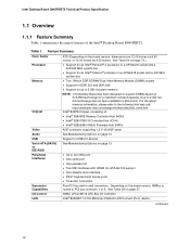
...ports • One serial port • One parallel port • Two IDE interfaces with a 400 MHz system bus • Two 184-pin DDR SDRAM Dual Inline Memory Module (DIMM) sockets • Support for DDR 333 and DDR 266 • Support for up to 2 GB ... 12 Table 1. See Table 54 on page 74.) • Support for an Intel® Pentium® 4 processor in card connectors. See Table 29 on this technology has not been validated on page 57. Intel Desktop Board D845PEBT2 Technical Product Specification 1.1 Overview 1.1.1 Feature Summary Table 1 summarizes the major features of...
...ports • One serial port • One parallel port • Two IDE interfaces with a 400 MHz system bus • Two 184-pin DDR SDRAM Dual Inline Memory Module (DIMM) sockets • Support for DDR 333 and DDR 266 • Support for up to 2 GB ... 12 Table 1. See Table 54 on page 74.) • Support for an Intel® Pentium® 4 processor in card connectors. See Table 29 on this technology has not been validated on page 57. Intel Desktop Board D845PEBT2 Technical Product Specification 1.1 Overview 1.1.1 Feature Summary Table 1 summarizes the major features of...

Product Specification
Page 20
... 20-pin and 4-pin leads of supported processors for the Desktop Board D845PEBT2. The Desktop Board D845PEBT2 will not boot. CAUTION Use of supported processors for the Desktop Board D845PEBT2 is available from Intel's World Wide Web site. See the processor's data sheet for the processor. For information about Supported processors Processor data sheets Power supply connectors...
... 20-pin and 4-pin leads of supported processors for the Desktop Board D845PEBT2. The Desktop Board D845PEBT2 will not boot. CAUTION Use of supported processors for the Desktop Board D845PEBT2 is available from Intel's World Wide Web site. See the processor's data sheet for the processor. For information about Supported processors Processor data sheets Power supply connectors...
Product Specification
Page 26
... an add-in hard drive controller. The LED indicates when data is plugged in hard drive controller and the IDE controller. Intel Desktop Board D845PEBT2 Technical Product Specification ✏ NOTE The BIOS will be wired to the LED output of the add-in hard drive controller ...to Figure 14, page 61 Table 41, page 66 Section 1.8, page 27 1.7.3.2 SCSI Hard Drive Activity LED Connector The SCSI hard drive activity LED connector is a 1 x 2-pin connector...
... an add-in hard drive controller. The LED indicates when data is plugged in hard drive controller and the IDE controller. Intel Desktop Board D845PEBT2 Technical Product Specification ✏ NOTE The BIOS will be wired to the LED output of the add-in hard drive controller ...to Figure 14, page 61 Table 41, page 66 Section 1.8, page 27 1.7.3.2 SCSI Hard Drive Activity LED Connector The SCSI hard drive activity LED connector is a 1 x 2-pin connector...
Product Specification
Page 28
...smsc.com 1.10.1 Serial Ports The Desktop Board D845PEBT2 has one serial port connector located on the back panel. For information about The location of the parallel port connector The signal names of the parallel port connector Setting the parallel port's mode Refer to Figure ...-pin D-Sub parallel port connector is located on the back panel. For information about The location of the serial port connector The signal names of the diskette drive connector The supported diskette drive capacities and sizes Refer to set the parallel port mode. Intel Desktop Board D845PEBT2 Technical...
...smsc.com 1.10.1 Serial Ports The Desktop Board D845PEBT2 has one serial port connector located on the back panel. For information about The location of the parallel port connector The signal names of the parallel port connector Setting the parallel port's mode Refer to Figure ...-pin D-Sub parallel port connector is located on the back panel. For information about The location of the serial port connector The signal names of the diskette drive connector The supported diskette drive capacities and sizes Refer to set the parallel port mode. Intel Desktop Board D845PEBT2 Technical...
Product Specification
Page 30
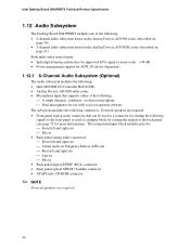
Powered speakers are required. 30 The connector/jumper block includes pins for: Front left and right out Mic in • Back panel analog audio connectors: Front left and right out Center and Low Frequency Effects (LFE) out &#... • Analog Devices AD1980 audio codec • Microphone input that supports either of the following connectors. Intel Desktop Board D845PEBT2 Technical Product Specification 1.12 Audio Subsystem The Desktop Board D845PEBT2 includes one of the following: A single dynamic, condenser, or electret microphone ...
Powered speakers are required. 30 The connector/jumper block includes pins for: Front left and right out Mic in • Back panel analog audio connectors: Front left and right out Center and Low Frequency Effects (LFE) out &#... • Analog Devices AD1980 audio codec • Microphone input that supports either of the following connectors. Intel Desktop Board D845PEBT2 Technical Product Specification 1.12 Audio Subsystem The Desktop Board D845PEBT2 includes one of the following: A single dynamic, condenser, or electret microphone ...
Product Specification
Page 31
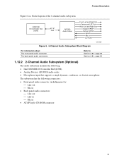
...includes the following: • Intel 82801DB I/O Controller Hub (ICH4) • Analog Devices AD1981B audio codec • Microphone input that supports a single dynamic, condenser, or electret microphone The subsystem has the following connectors: • Front panel audio connector, including pins for: Line ...out Mic in • Back panel audio connectors: Line out Line in Mic in &#...
...includes the following: • Intel 82801DB I/O Controller Hub (ICH4) • Analog Devices AD1981B audio codec • Microphone input that supports a single dynamic, condenser, or electret microphone The subsystem has the following connectors: • Front panel audio connector, including pins for: Line ...out Mic in • Back panel audio connectors: Line out Line in Mic in &#...
Product Specification
Page 53
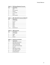
... Signal Name +12V (Fused) Ground TPB1TPB1+ TPA1TPA1+ Shield Ground Table 18. Table 16. Serial Port A Connector Pin Signal Name 1 DCD (Data Carrier Detect) 2 RXD# (Receive Data) 3 TXD# (Transmit Data) 4 DTR (Data Terminal Ready) 5 Ground... Set Ready) 7 RTS (Request to Send) 8 CTS (Clear to Send) 9 RI (Ring Indicator) Technical Reference 53 USB Connectors Pin Signal Name 1 +5 V (Fused) 2 USB# 3 USB 4 Ground Table 19. PS/2 Mouse/Keyboard Connector Pin Signal Name 1 Data 2 Not connected 3 Ground 4 +5 V (Fused) 5 Clock 6 Not connected Table 17.
... Signal Name +12V (Fused) Ground TPB1TPB1+ TPA1TPA1+ Shield Ground Table 18. Table 16. Serial Port A Connector Pin Signal Name 1 DCD (Data Carrier Detect) 2 RXD# (Receive Data) 3 TXD# (Transmit Data) 4 DTR (Data Terminal Ready) 5 Ground... Set Ready) 7 RTS (Request to Send) 8 CTS (Clear to Send) 9 RI (Ring Indicator) Technical Reference 53 USB Connectors Pin Signal Name 1 +5 V (Fused) 2 USB# 3 USB 4 Ground Table 19. PS/2 Mouse/Keyboard Connector Pin Signal Name 1 Data 2 Not connected 3 Ground 4 +5 V (Fused) 5 Clock 6 Not connected Table 17.
Product Specification
Page 54
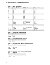
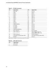
... out Ring Rear right out Sleeve Ground Table 24. Digital S/PDIF Connector (Optional) Pin Tip Sleeve Signal Name S/PDIF Ground Table 22. Audio Center and LFE Out Connector (Optional) Pin Tip Ring Sleeve Signal Name Center out LFE out Ground 54 Parallel Port Connector Pin 1 2 3 4 5 6 7 8 9 10 11 12 13 14 15 16 17 18 - 25 Standard...# SLCTIN# Ground EPP Signal Name WRITE# PD0 PD1 PD2 PD3 PD4 PD5 PD6 PD7 INTR WAIT# PE SELECT DATASTB# FAULT# RESET# ADDRSTB# Ground Table 21. Intel Desktop Board D845PEBT2 Technical Product Specification Table 20.
... out Ring Rear right out Sleeve Ground Table 24. Digital S/PDIF Connector (Optional) Pin Tip Sleeve Signal Name S/PDIF Ground Table 22. Audio Center and LFE Out Connector (Optional) Pin Tip Ring Sleeve Signal Name Center out LFE out Ground 54 Parallel Port Connector Pin 1 2 3 4 5 6 7 8 9 10 11 12 13 14 15 16 17 18 - 25 Standard...# SLCTIN# Ground EPP Signal Name WRITE# PD0 PD1 PD2 PD3 PD4 PD5 PD6 PD7 INTR WAIT# PE SELECT DATASTB# FAULT# RESET# ADDRSTB# Ground Table 21. Intel Desktop Board D845PEBT2 Technical Product Specification Table 20.
Product Specification
Page 55
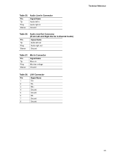
LAN Connector Pin Signal Name 1 TX+ 2 TX- 3 RX+ 4 Ground 5 Ground 6 RX- 7 Ground 8 Ground Technical Reference 55 Audio Line In Connector Pin Tip Ring Sleeve Signal Name Audio left out Ring Audio right out Sleeve Ground Table 27. Mic In Connector Pin Tip Ring Sleeve Signal Name Mono in Ground Table 26. Table 25. Audio Line Out Connector (Front Left and Right Out for 6-Channel Audio) Pin Signal Name Tip Audio left in Audio right in Mic bias voltage Ground Table 28.
LAN Connector Pin Signal Name 1 TX+ 2 TX- 3 RX+ 4 Ground 5 Ground 6 RX- 7 Ground 8 Ground Technical Reference 55 Audio Line In Connector Pin Tip Ring Sleeve Signal Name Audio left out Ring Audio right out Sleeve Ground Table 27. Mic In Connector Pin Tip Ring Sleeve Signal Name Mono in Ground Table 26. Table 25. Audio Line Out Connector (Front Left and Right Out for 6-Channel Audio) Pin Signal Name Tip Audio left in Audio right in Mic bias voltage Ground Table 28.
Product Specification
Page 59
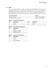
... that provides required supplemental power for the Intel Pentium 4 processor. The Desktop Board D845PEBT2 will not boot with the Desktop Board D845PEBT2. Use only ATX12V-compliant power supplies with a standard ATX power supply. Processor Fan Connector Pin Signal Name 1 Control 2 +12 V 3 CPU_FAN_TACH 59 ATX12V Power Connector Pin Signal Name 1 Ground 3 +12 V Pin Signal Name 2 Ground 4 +12 V Table 31...
... that provides required supplemental power for the Intel Pentium 4 processor. The Desktop Board D845PEBT2 will not boot with the Desktop Board D845PEBT2. Use only ATX12V-compliant power supplies with a standard ATX power supply. Processor Fan Connector Pin Signal Name 1 Control 2 +12 V 3 CPU_FAN_TACH 59 ATX12V Power Connector Pin Signal Name 1 Ground 3 +12 V Pin Signal Name 2 Ground 4 +12 V Table 31...
Product Specification
Page 60
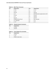
Chassis Intrusion Connector Pin Signal Name 1 Intruder 2 Ground Table 35. Front Chassis Fan Connector Pin Signal Name 1 Control 2 +12 V 3 FRONT_FAN_TACH Signal Name +3.3 V -12 V Ground PS-ON# (power supply remote on/off) Ground Ground Ground Not connected +5 V +5 V 60 Main Power Connector Pin Signal Name Pin 1 +3.3 V 11 2 +3.3 V 12 3 Ground 13 4 +5 V 14 5 Ground 15 6 +5 V 16 7 Ground 17 8 PWRGD (Power Good) 18 9 +5 V (Standby) 19 10 +12 V 20 Table 34. Intel Desktop Board D845PEBT2 Technical Product Specification Table 33.
Chassis Intrusion Connector Pin Signal Name 1 Intruder 2 Ground Table 35. Front Chassis Fan Connector Pin Signal Name 1 Control 2 +12 V 3 FRONT_FAN_TACH Signal Name +3.3 V -12 V Ground PS-ON# (power supply remote on/off) Ground Ground Ground Not connected +5 V +5 V 60 Main Power Connector Pin Signal Name Pin 1 +3.3 V 11 2 +3.3 V 12 3 Ground 13 4 +5 V 14 5 Ground 15 6 +5 V 16 7 Ground 17 8 PWRGD (Power Good) 18 9 +5 V (Standby) 19 10 +12 V 20 Table 34. Intel Desktop Board D845PEBT2 Technical Product Specification Table 33.
Product Specification
Page 63
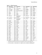
Technical Reference Table 37. PCI Bus Connectors Pin Signal Name Pin Signal Name Pin Signal Name A1 Ground (TRST#)* B1 -12 V A32 AD16 A2 +12 V B2 ...INTC# B7 INTB# A38 STOP# A8 +5 V B8 INTD# A39 +3.3 V A9 Reserved B9 Not connected (PRSNT1#)* A40 Reserved ** Pin Signal Name B32 AD17 B33 C/BE2# B34 Ground B35 IRDY# B36 +3.3 V B37 DEVSEL# B38 Ground B39 LOCK# B40 PERR# .... ** On PCI bus connector 1 or 2 (see section 2.8.2.1 on page 57), this pin is connected to the SMBus clock line. *** On PCI bus connector 1 or 2 (see section 2.8.2.1 on page 57), this pin is connected to the SMBus...
Technical Reference Table 37. PCI Bus Connectors Pin Signal Name Pin Signal Name Pin Signal Name A1 Ground (TRST#)* B1 -12 V A32 AD16 A2 +12 V B2 ...INTC# B7 INTB# A38 STOP# A8 +5 V B8 INTD# A39 +3.3 V A9 Reserved B9 Not connected (PRSNT1#)* A40 Reserved ** Pin Signal Name B32 AD17 B33 C/BE2# B34 Ground B35 IRDY# B36 +3.3 V B37 DEVSEL# B38 Ground B39 LOCK# B40 PERR# .... ** On PCI bus connector 1 or 2 (see section 2.8.2.1 on page 57), this pin is connected to the SMBus clock line. *** On PCI bus connector 1 or 2 (see section 2.8.2.1 on page 57), this pin is connected to the SMBus...
Product Specification
Page 64
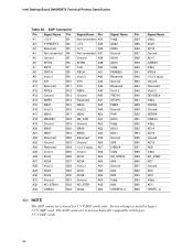
Intel Desktop Board D845PEBT2 Technical Product Specification Table 38. Do not attempt to install a legacy 3.3 V AGP card. The AGP connector is keyed for 1.5 V AGP cards only. AGP Connector Pin Signal Name Pin A1 +12 V B1 A2 TYPEDET# B2 A3 Reserved B3 A4 Not connected B4 A5 Ground B5 A6 INTA# B6 ... (aux) A57 Vcc3.3 A58 AD31 A59 AD29 A60 Vcc3.3 A61 AD27 A62 AD25 A63 Ground A64 AD_STB1 A65 AD23 A66 Signal Name Pin Vddq B34 AD22 B35 AD20 B36 Ground B37 AD18 B38 AD16 B39 Vddq B40 FRAME# B41 Reserved B42 Ground B43 Reserved B44 Vcc3.3 ...
Intel Desktop Board D845PEBT2 Technical Product Specification Table 38. Do not attempt to install a legacy 3.3 V AGP card. The AGP connector is keyed for 1.5 V AGP cards only. AGP Connector Pin Signal Name Pin A1 +12 V B1 A2 TYPEDET# B2 A3 Reserved B3 A4 Not connected B4 A5 Ground B5 A6 INTA# B6 ... (aux) A57 Vcc3.3 A58 AD31 A59 AD29 A60 Vcc3.3 A61 AD27 A62 AD25 A63 Ground A64 AD_STB1 A65 AD23 A66 Signal Name Pin Vddq B34 AD22 B35 AD20 B36 Ground B37 AD18 B38 AD16 B39 Vddq B40 FRAME# B41 Reserved B42 Ground B43 Reserved B44 Vcc3.3 ...
Product Specification
Page 65
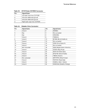
... 1 Left audio input from CD-ROM 2 CD audio differential ground 3 CD audio differential ground 4 Right audio input from CD-ROM Table 40. Diskette Drive Connector Pin Signal Name Pin 1 Ground 2 3 Key 4 5 Key 6 7 Ground 8 9 Ground 10 11 Ground 12 13 Ground 14 15 Ground 16 17 Not connected 18 19 Ground 20 21 Ground...
... 1 Left audio input from CD-ROM 2 CD audio differential ground 3 CD audio differential ground 4 Right audio input from CD-ROM Table 40. Diskette Drive Connector Pin Signal Name Pin 1 Ground 2 3 Key 4 5 Key 6 7 Ground 8 9 Ground 10 11 Ground 12 13 Ground 14 15 Ground 16 17 Not connected 18 19 Ground 20 21 Ground...
Product Specification
Page 66
PCI IDE Connectors Pin Signal Name Pin 1 Reset IDE 2 3 Data 7 4 5 Data 6 6 7 Data 5 8 9 Data 4 10 11 Data 3 12 13 Data 2 14 15 Data 1 16 17 Data 0 18 19 Ground 20 21 DDRQ0 [DDRQ1]...secondary IDE connector. SCSI LED Connector Pin Signal Name 1 SCSI_ACT# 2 No connect Signal Name Ground Data 8 Data 9 Data 10 Data 11 Data 12 Data 13 Data 14 Data 15 Key Ground Ground Ground Ground Ground Not connected GPIO_DMA66_Detect_Pri [GPIO_DMA66_Detect_Sec] DAG2 (Address 2) Chip Select 3P# [Chip Select 3S#] Ground 66 Intel Desktop Board D845PEBT2 Technical Product...
PCI IDE Connectors Pin Signal Name Pin 1 Reset IDE 2 3 Data 7 4 5 Data 6 6 7 Data 5 8 9 Data 4 10 11 Data 3 12 13 Data 2 14 15 Data 1 16 17 Data 0 18 19 Ground 20 21 DDRQ0 [DDRQ1]...secondary IDE connector. SCSI LED Connector Pin Signal Name 1 SCSI_ACT# 2 No connect Signal Name Ground Data 8 Data 9 Data 10 Data 11 Data 12 Data 13 Data 14 Data 15 Key Ground Ground Ground Ground Ground Not connected GPIO_DMA66_Detect_Pri [GPIO_DMA66_Detect_Sec] DAG2 (Address 2) Chip Select 3P# [Chip Select 3S#] Ground 66 Intel Desktop Board D845PEBT2 Technical Product...
Product Specification
Page 69
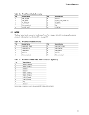
... Ground Signal names in brackets [ ] are for routing audio signals. For more information, see Section 2.9.1 on page 72. Technical Reference Table 45. Front Panel USB Connector Pin Signal Name Pin Signal Name 1 USB_FNT_PWR 2 USB_FNT_PWR 3 USB_FNT1# 4 USB_FNT2# 5 USB_FNT1 6 USB_FNT2 7 Ground 8 Ground 9 Not connected 10 Not connected Table 47. Table 46. Front Panel Audio...
... Ground Signal names in brackets [ ] are for routing audio signals. For more information, see Section 2.9.1 on page 72. Technical Reference Table 45. Front Panel USB Connector Pin Signal Name Pin Signal Name 1 USB_FNT_PWR 2 USB_FNT_PWR 3 USB_FNT1# 4 USB_FNT2# 5 USB_FNT1 6 USB_FNT2 7 Ground 8 Ground 9 Not connected 10 Not connected Table 47. Table 46. Front Panel Audio...
Product Specification
Page 70
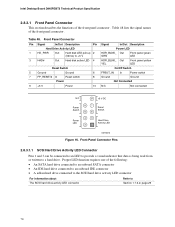
...Drive Activity LED 1 HD_PWR Out Hard disk LED pull-up 2 (330 Ω) to a hard drive. Front Panel Connector Pins 2.8.3.1.1 SCSI Hard Drive Activity LED Connector Pins 1 and 3 can be connected to an LED to provide a visual indicator that data is being read from or ... LED Activity LED 2 1 OM15075 Figure 16. Intel Desktop Board D845PEBT2 Technical Product Specification 2.8.3.1 Front Panel Connector This section describes the functions of the front panel connector. Table 48 lists the signal names of the front panel connector. Proper LED function requires one of the following:...
...Drive Activity LED 1 HD_PWR Out Hard disk LED pull-up 2 (330 Ω) to a hard drive. Front Panel Connector Pins 2.8.3.1.1 SCSI Hard Drive Activity LED Connector Pins 1 and 3 can be connected to an LED to provide a visual indicator that data is being read from or ... LED Activity LED 2 1 OM15075 Figure 16. Intel Desktop Board D845PEBT2 Technical Product Specification 2.8.3.1 Front Panel Connector This section describes the functions of the front panel connector. Table 48 lists the signal names of the front panel connector. Proper LED function requires one of the following:...
Product Specification
Page 71
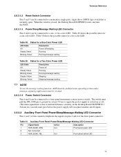
... Blinking Yellow Description Power off /sleeping Running Running/message waiting Table 50. When the switch is closed, the Desktop Board D845PEBT2 resets and runs the POST. 2.8.3.1.3 Power/Sleep/Message Waiting LED Connector Pins 2 and 4 can be connected to a momentary single pole, single throw (SPST) type switch that is due to internal debounce circuitry...
... Blinking Yellow Description Power off /sleeping Running Running/message waiting Table 50. When the switch is closed, the Desktop Board D845PEBT2 resets and runs the POST. 2.8.3.1.3 Power/Sleep/Message Waiting LED Connector Pins 2 and 4 can be connected to a momentary single pole, single throw (SPST) type switch that is due to internal debounce circuitry...
Specification Update
Page 14
... bus connector 1 or 2 depending on the Desktop Board D845PEBT2. PCI slots are identified as PCI slot #x, starting with respect to processor location on the board configuration (See Table 29). The ATX numbering convention is not numbered. The ECN specifies that implement PCI bus connector pins A40 ...locations with respect to the far edge of the SMBus to the PCI Connector ECN", dated October 5th, 2000. Intel Desktop Board D845PEBT2 Specification Update ✏ NOTE The SMBus routing to the PCI bus connectors does not conform to the PCI Engineering Change Notice (ECN) "Addition ...
... bus connector 1 or 2 depending on the Desktop Board D845PEBT2. PCI slots are identified as PCI slot #x, starting with respect to processor location on the board configuration (See Table 29). The ATX numbering convention is not numbered. The ECN specifies that implement PCI bus connector pins A40 ...locations with respect to the far edge of the SMBus to the PCI Connector ECN", dated October 5th, 2000. Intel Desktop Board D845PEBT2 Specification Update ✏ NOTE The SMBus routing to the PCI bus connectors does not conform to the PCI Engineering Change Notice (ECN) "Addition ...


