
Product Guide
Page 5
... 13 Integrated Graphics Subsystem 14 Intel® NM10 Express Chipset 14 Operating System Support 14 Onboard Audio Subsystem 14 Legacy Input/Output (I/O) Controller 16 LAN Subsystem 16 USB 2.0 Support 17 SATA Interface 17 Expandability...17 BIOS ...18 PCI/PCI Express Auto Configuration 18 Security Passwords...Desktop Board 27 Installing and Removing Memory 28 Connecting SATA Drives 29 Installing a Wireless LAN Card in the PCI Express Mini Card Slot 30 Installing an Intel® Z-U130 USB Solid-State Drive or Compatible Device 32 Connecting to the Internal Headers 33 Connecting ...
... 13 Integrated Graphics Subsystem 14 Intel® NM10 Express Chipset 14 Operating System Support 14 Onboard Audio Subsystem 14 Legacy Input/Output (I/O) Controller 16 LAN Subsystem 16 USB 2.0 Support 17 SATA Interface 17 Expandability...17 BIOS ...18 PCI/PCI Express Auto Configuration 18 Security Passwords...Desktop Board 27 Installing and Removing Memory 28 Connecting SATA Drives 29 Installing a Wireless LAN Card in the PCI Express Mini Card Slot 30 Installing an Intel® Z-U130 USB Solid-State Drive or Compatible Device 32 Connecting to the Internal Headers 33 Connecting ...
Product Guide
Page 9
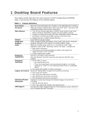
...Table 1 summarizes the features of Intel® Desktop Board D525MW. Table 1. Included are: • Back panel connectors • Front panel microphone/headphone header with support for 5.1 (6-channel) Intel® High Definition Audio (Intel® HD Audio) and AC '97 Audio. one header supports an Intel® Z-U130 USB Solid-... subsystem with support for analog displays (VGA) RealTek* ALC662 audio codec for Intel® HD Audio or AC '97 Audio • S/PDIF digital audio header One PCI* bus add-in card connector One PCI Express* Full-Mini Card slot with speed control 10/100/1000 Mb/s (...
...Table 1 summarizes the features of Intel® Desktop Board D525MW. Table 1. Included are: • Back panel connectors • Front panel microphone/headphone header with support for 5.1 (6-channel) Intel® High Definition Audio (Intel® HD Audio) and AC '97 Audio. one header supports an Intel® Z-U130 USB Solid-... subsystem with support for analog displays (VGA) RealTek* ALC662 audio codec for Intel® HD Audio or AC '97 Audio • S/PDIF digital audio header One PCI* bus add-in card connector One PCI Express* Full-Mini Card slot with speed control 10/100/1000 Mb/s (...
Product Guide
Page 10
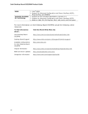
... Configuration and Power Interface (ACPI) • Wake on USB, PCI, PCI Express, PS/2, LAN, serial, and front panel For more information on Intel Desktop Board D525MW consult the following online resources: To find information about... Intel Desktop Board D525MW Product Guide BIOS Instantly Available PC Technology • Intel® BIOS • Support for Advanced Configuration and Power...
... Configuration and Power Interface (ACPI) • Wake on USB, PCI, PCI Express, PS/2, LAN, serial, and front panel For more information on Intel Desktop Board D525MW consult the following online resources: To find information about... Intel Desktop Board D525MW Product Guide BIOS Instantly Available PC Technology • Intel® BIOS • Support for Advanced Configuration and Power...
Product Guide
Page 16
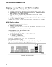
Figure 3. LAN Status LEDs 16 Two LEDs are available from Intel's World Wide Web site at http://downloadcenter.intel.com/. Intel Desktop Board D525MW Product Guide Legacy Input/Output (I/O) Controller The legacy I /O controller. These LEDs indicate the operating states of... the LAN subsystem include: • CSMA/CD protocol engine • LAN connect interface that supports the ethernet controller • PCI bus...
Figure 3. LAN Status LEDs 16 Two LEDs are available from Intel's World Wide Web site at http://downloadcenter.intel.com/. Intel Desktop Board D525MW Product Guide Legacy Input/Output (I/O) Controller The legacy I /O controller. These LEDs indicate the operating states of... the LAN subsystem include: • CSMA/CD protocol engine • LAN connect interface that supports the ethernet controller • PCI bus...

Product Guide
Page 17
... Disabling High-Speed USB in the BIOS reverts all USB 2.0 ports to the cable. One of the front panel USB headers supports an Intel Z-U130 USB Solid-State Drive or compatible device. Use a shielded cable that support one device per channel. SATA Interface The Desktop Board ... headers). The connector can operate in card or a single- The SATA controller supports IDE and ACHI configuration and can support either a single PCI add-in both an operating system and drivers that do not support USB 2.0. Table 4. NOTE Computer systems that have an unshielded cable attached to...
... Disabling High-Speed USB in the BIOS reverts all USB 2.0 ports to the cable. One of the front panel USB headers supports an Intel Z-U130 USB Solid-State Drive or compatible device. Use a shielded cable that support one device per channel. SATA Interface The Desktop Board ... headers). The connector can operate in card or a single- The SATA controller supports IDE and ACHI configuration and can support either a single PCI add-in both an operating system and drivers that do not support USB 2.0. Table 4. NOTE Computer systems that have an unshielded cable attached to...

Product Guide
Page 18
... supervisor password gives unrestricted access to run the BIOS Setup program after you install a PCI/PCI Express add-in card in your computer, the PCI/PCI Express auto-configuration utility in card. Intel Desktop Board D525MW Product Guide BIOS The BIOS provides the Power-On Self-Test (POST), the BIOS ...Setup program, the PCI and SATA auto-configuration utilities, and the video BIOS. For ...
... supervisor password gives unrestricted access to run the BIOS Setup program after you install a PCI/PCI Express add-in card in your computer, the PCI/PCI Express auto-configuration utility in card. Intel Desktop Board D525MW Product Guide BIOS The BIOS provides the Power-On Self-Test (POST), the BIOS ...Setup program, the PCI and SATA auto-configuration utilities, and the video BIOS. For ...

Product Guide
Page 19
... ACPI gives the operating system direct control over the power management and Plug and Play functions of a computer. This includes the DIMM sockets and the PCI bus connector, even though the computer appears to be off and the standby power indicator is still lit, disconnect the power cord before installing or...
... ACPI gives the operating system direct control over the power management and Plug and Play functions of a computer. This includes the DIMM sockets and the PCI bus connector, even though the computer appears to be off and the standby power indicator is still lit, disconnect the power cord before installing or...

Product Guide
Page 20
The board supports the PCI Bus Power Management Interface Specification. The use of the Standby Power Indicator For more information on the Intel Desktop D525MW web page at http://www.intel.com/products/motherboard/D525MW/index.htm. Intel Desktop Board D525MW Product Guide Figure 4. When signaled by a wake-up device ... will power off, the front panel power LED will blink). Location of Instantly Available PC technology requires operating system support and PCI 2.3 compliant add-in the ACPI S3 sleep-state, the computer will appear to be used to the Technical Product Specification on...
The board supports the PCI Bus Power Management Interface Specification. The use of the Standby Power Indicator For more information on the Intel Desktop D525MW web page at http://www.intel.com/products/motherboard/D525MW/index.htm. Intel Desktop Board D525MW Product Guide Figure 4. When signaled by a wake-up device ... will power off, the front panel power LED will blink). Location of Instantly Available PC technology requires operating system support and PCI 2.3 compliant add-in the ACPI S3 sleep-state, the computer will appear to be used to the Technical Product Specification on...

Product Guide
Page 21
... only PS/2 activity that powers up of a USB peripheral that supports wake from USB. PME# Wakeup Support When the PME# signal is asserted on the PCI bus, the computer wakes from an ACPI S1 or S3 state. Wake from PS/2 Device PS/2 keyboard activity wakes the computer from an ACPI S1... activity wakes the computer from an ACPI S1, S3, S4, or S5 state. WAKE# Signal Wakeup Support When the WAKE# signal is asserted on the PCI Express bus, the computer wakes from an ACPI S1, S3, S4, or S5 state.
... only PS/2 activity that powers up of a USB peripheral that supports wake from USB. PME# Wakeup Support When the PME# signal is asserted on the PCI bus, the computer wakes from an ACPI S1 or S3 state. Wake from PS/2 Device PS/2 keyboard activity wakes the computer from an ACPI S1... activity wakes the computer from an ACPI S1, S3, S4, or S5 state. WAKE# Signal Wakeup Support When the WAKE# signal is asserted on the PCI Express bus, the computer wakes from an ACPI S1, S3, S4, or S5 state.

Product Guide
Page 30
...supplied screws. 4. Figure 9. Attach your system's antenna wires to the connectors (Figure 9, C) on page 23. 2. Intel Desktop Board D525MW Product Guide Installing a Wireless LAN Card in the PCI Express Mini Card Slot A wireless LAN card can be installed in "Before You Begin" on the wireless LAN card ...as shown. Observe the precautions in the Desktop Board's PCI Express Mini Card slot. Installing a Full-Mini...
...supplied screws. 4. Figure 9. Attach your system's antenna wires to the connectors (Figure 9, C) on page 23. 2. Intel Desktop Board D525MW Product Guide Installing a Wireless LAN Card in the PCI Express Mini Card Slot A wireless LAN card can be installed in "Before You Begin" on the wireless LAN card ...as shown. Observe the precautions in the Desktop Board's PCI Express Mini Card slot. Installing a Full-Mini...

Product Guide
Page 31
... wires to the connectors (Figure 10, D) on page 23. 2. Align the card's mounting holes (Figure 10, C) with the plastic latch and snap it into the PCI Express Mini Card connector (Figure 10, B) at a slightly upward angle. 4. Installing a Half-Mini Card Wireless LAN Card 31 Figure 10. Insert the plastic Half-Mini...
... wires to the connectors (Figure 10, D) on page 23. 2. Align the card's mounting holes (Figure 10, C) with the plastic latch and snap it into the PCI Express Mini Card connector (Figure 10, B) at a slightly upward angle. 4. Installing a Half-Mini Card Wireless LAN Card 31 Figure 10. Insert the plastic Half-Mini...

Product Specification
Page 6
vi Intel Desktop Board D525MW and Intel Desktop Board D525MWV Technical Product Specification 2.7 Power Consumption ...2.7.1 Minimum Load Configuration...2.7.2 Maximum Load Configuration ...2.8 Reliability ...2.9 Environmental ...3.1 Introduction ...3.2 BIOS Flash Memory Organization ...3.3 Resource Configuration ...3.3.1 PCI* Autoconfiguration...3.4 System Management BIOS (SMBIOS)...3.5 Legacy USB Support ...3.6 BIOS Updates ...3.6.1 BIOS Recovery...3.6.2 Custom Splash Screen ...3.7 Boot Options...3.7.1 Optical Drive Boot ...3.7.2 Network Boot...3.7.3 Booting Without...
vi Intel Desktop Board D525MW and Intel Desktop Board D525MWV Technical Product Specification 2.7 Power Consumption ...2.7.1 Minimum Load Configuration...2.7.2 Maximum Load Configuration ...2.8 Reliability ...2.9 Environmental ...3.1 Introduction ...3.2 BIOS Flash Memory Organization ...3.3 Resource Configuration ...3.3.1 PCI* Autoconfiguration...3.4 System Management BIOS (SMBIOS)...3.5 Legacy USB Support ...3.6 BIOS Updates ...3.6.1 BIOS Recovery...3.6.2 Custom Splash Screen ...3.7 Boot Options...3.7.1 Optical Drive Boot ...3.7.2 Network Boot...3.7.3 Booting Without...

Product Specification
Page 10
Intel Desktop Board D525MW and Intel Desktop Board D525MWV Technical Product Specification Table 1. Feature Summary (continued) BIOS • Intel® BIOS (resident in the SPI Flash device) • Support for Advanced Configuration and Power Interface (ACPI), Plug and Play, and SMBIOS Instantly Available PC Technology Expansion Capabilities Hardware Monitor Subsystem • Support for PCI* Local Bus...
Intel Desktop Board D525MW and Intel Desktop Board D525MWV Technical Product Specification Table 1. Feature Summary (continued) BIOS • Intel® BIOS (resident in the SPI Flash device) • Support for Advanced Configuration and Power Interface (ACPI), Plug and Play, and SMBIOS Instantly Available PC Technology Expansion Capabilities Hardware Monitor Subsystem • Support for PCI* Local Bus...

Product Specification
Page 12
...jumper (D525MWV only) LVDS inverter power connector (D525MWV only) LVDS panel connector (D525MWV only) Processor core power connector (2 x 2) Intel Atom processor Power connector (2 x 12) SO-DIMM channel A socket, DIMM 0 SO-DIMM channel A socket, DIMM 1 Battery ...PCI Express x1 Mini Card connector Intel NM10 Express Chipset Front Panel Wireless Activity LED Header Front panel USB header supports Intel Z-U130 USB Solid-State Drive or compatible device (brown-colored) PCI conventional bus connector S/PDIF header Chassis fan header Front panel audio header 12 Intel Desktop Board D525MW and Intel...
...jumper (D525MWV only) LVDS inverter power connector (D525MWV only) LVDS panel connector (D525MWV only) Processor core power connector (2 x 2) Intel Atom processor Power connector (2 x 12) SO-DIMM channel A socket, DIMM 0 SO-DIMM channel A socket, DIMM 1 Battery ...PCI Express x1 Mini Card connector Intel NM10 Express Chipset Front Panel Wireless Activity LED Header Front panel USB header supports Intel Z-U130 USB Solid-State Drive or compatible device (brown-colored) PCI conventional bus connector S/PDIF header Chassis fan header Front panel audio header 12 Intel Desktop Board D525MW and Intel...

Product Specification
Page 17
... 17 Dynamic allocation of 2-D/3-D graphics performance and overall system performance. For information about The Intel NM10 Express chipset Resources used by the chipset Refer to http://www.intel.com/products/desktop/chipsets/index.htm Chapter 2 1.5.1.1 Video Memory Allocation Video memory is allocated...to UXGA (1366 x 768) 25 MHz to the processor and the USB, SATA, LPC, LAN, PCI, and PCI Express interfaces. Product Description 1.5 Intel® NM10 Express Chipset The Intel NM10 Express Chipset provides interfaces to 112 MHz single-channel; @18 bpp ⎯ TFT panel type Panel ...
... 17 Dynamic allocation of 2-D/3-D graphics performance and overall system performance. For information about The Intel NM10 Express chipset Resources used by the chipset Refer to http://www.intel.com/products/desktop/chipsets/index.htm Chapter 2 1.5.1.1 Video Memory Allocation Video memory is allocated...to UXGA (1366 x 768) 25 MHz to the processor and the USB, SATA, LPC, LAN, PCI, and PCI Express interfaces. Product Description 1.5 Intel® NM10 Express Chipset The Intel NM10 Express Chipset provides interfaces to 112 MHz single-channel; @18 bpp ⎯ TFT panel type Panel ...

Product Specification
Page 19
... offers independent SATA ports with a theoretical maximum transfer rate of the front panel USB headers (brown-colored) supports an Intel Z-U130 USB Solid-State Drive or compatible device. In native mode, standard PCI Conventional bus resource steering is the preferred mode for host to the operating system. A point-to Section 1.2, page 14...
... offers independent SATA ports with a theoretical maximum transfer rate of the front panel USB headers (brown-colored) supports an Intel Z-U130 USB Solid-State Drive or compatible device. In native mode, standard PCI Conventional bus resource steering is the preferred mode for host to the operating system. A point-to Section 1.2, page 14...

Product Specification
Page 20
... bus systems PS/2-style keyboard and mouse ports Intelligent power management, including a programmable wake-up event interface PCI Conventional bus power management support The Legacy I /O controller. Intel Desktop Board D525MW and Intel Desktop Board D525MWV Technical Product Specification 1.6 Real-Time Clock Subsystem A coin-cell battery (CR2032) powers the real-time clock and CMOS memory...
... bus systems PS/2-style keyboard and mouse ports Intelligent power management, including a programmable wake-up event interface PCI Conventional bus power management support The Legacy I /O controller. Intel Desktop Board D525MW and Intel Desktop Board D525MWV Technical Product Specification 1.6 Real-Time Clock Subsystem A coin-cell battery (CR2032) powers the real-time clock and CMOS memory...

Product Specification
Page 21
... LAN drivers 21 Product Description 1.8 LAN Subsystem Intel NM10 Express Chipset Realtek 8111E Gigabit Ethernet Controller for 10/100/1000 Mbit/s Ethernet LAN connectivity RJ-45 LAN connector with integrated status LEDs CSMA/CD protocol engine LAN connect interface that supports the Ethernet controller PCI Conventional bus power management ⎯ Supports ACPI...
... LAN drivers 21 Product Description 1.8 LAN Subsystem Intel NM10 Express Chipset Realtek 8111E Gigabit Ethernet Controller for 10/100/1000 Mbit/s Ethernet LAN connectivity RJ-45 LAN connector with integrated status LEDs CSMA/CD protocol engine LAN connect interface that supports the Ethernet controller PCI Conventional bus power management ⎯ Supports ACPI...

Product Specification
Page 31
... on some keyboards. 1.11.2.7 WAKE# Signal Wake-up device or event, the system quickly returns to its last known state. The board supports the PCI Bus Power Management Interface Specification. NOTE Wake from USB requires the use of a USB peripheral that will wake the computer is the Alt + Print Screen...management and can wake the computer from an ACPI S1 or S3 state. The use of Instantly Available PC technology requires operating system support and PCI 2.3 compliant add-in an ACPI S4 or S5 state, the only PS/2 activity that supports Wake from USB and support in the operating system...
... on some keyboards. 1.11.2.7 WAKE# Signal Wake-up device or event, the system quickly returns to its last known state. The board supports the PCI Bus Power Management Interface Specification. NOTE Wake from USB requires the use of a USB peripheral that will wake the computer is the Alt + Print Screen...management and can wake the computer from an ACPI S1 or S3 state. The use of Instantly Available PC technology requires operating system support and PCI 2.3 compliant add-in an ACPI S4 or S5 state, the only PS/2 activity that supports Wake from USB and support in the operating system...

Product Specification
Page 33
... functions. Typically the address space that has 4 GB of system memory installed, it is dynamically allocated for PCI Conventional bus add-in cards 33 On a system that is allocated for PCI Conventional add-in cards, PCI Express configuration space, BIOS (SPI Flash), and chipset overhead resides above the top of addressable system memory.
... functions. Typically the address space that has 4 GB of system memory installed, it is dynamically allocated for PCI Conventional bus add-in cards 33 On a system that is allocated for PCI Conventional add-in cards, PCI Express configuration space, BIOS (SPI Flash), and chipset overhead resides above the top of addressable system memory.

