
Product Specification
Page 5
... Summary 10 1.1.2 Block Diagram 11 1.1.3 Board Layout 12 1.2 Online Support ...14 1.3 Processor ...14 1.4 System Memory ...15 1.5 ATI Radeon* Xpress 200 Chipset 16 1.5.1 Graphics Subsystem 16 1.5.2 Firmware Hub (FWH 16 1.5.3 USB ...16 1.5.4 IDE Support 17 1.5.5 Real-Time Clock, CMOS SRAM, and Battery 18 1.6 PCI...1.10.1 Fan Monitoring 23 1.10.2 Chassis Intrusion and Detection 23 1.11 Power Management ...23 1.11.1 ACPI ...24 1.11.2 Hardware Support 26 2 Technical Reference 2.1 Memory Map ...31 2.2 DMA Channels ...32 2.3 Fixed I/O Map...33 2.4 Interrupts ...34 2.5 PCI Configuration ...
... Summary 10 1.1.2 Block Diagram 11 1.1.3 Board Layout 12 1.2 Online Support ...14 1.3 Processor ...14 1.4 System Memory ...15 1.5 ATI Radeon* Xpress 200 Chipset 16 1.5.1 Graphics Subsystem 16 1.5.2 Firmware Hub (FWH 16 1.5.3 USB ...16 1.5.4 IDE Support 17 1.5.5 Real-Time Clock, CMOS SRAM, and Battery 18 1.6 PCI...1.10.1 Fan Monitoring 23 1.10.2 Chassis Intrusion and Detection 23 1.11 Power Management ...23 1.11.1 ACPI ...24 1.11.2 Hardware Support 26 2 Technical Reference 2.1 Memory Map ...31 2.2 DMA Channels ...32 2.3 Fixed I/O Map...33 2.4 Interrupts ...34 2.5 PCI Configuration ...

Product Specification
Page 7
Board Dimensions...46 12. Localized High Temperature Zones 51 Tables 1. Supported System Bus Frequency and Memory Speed Combinations 15 4. LAN Connector LED States 22 6. Wake-up Devices and Events 25 9. I /O Shield Dimensions 47 13. ...Connectors Shown in Figure 6 37 16. Contents Figures 1. Front/Back Panel Audio Connector Options for Front Panel Connector 43 9. Serial ATA Connectors 40 20. Processor Fan Connector 40 21. Fan Connector Current Capability 49 31. Feature Summary ...10 2. PCI Interrupt Routing Map 35 15. States for Omni-directional Airflow ...
Board Dimensions...46 12. Localized High Temperature Zones 51 Tables 1. Supported System Bus Frequency and Memory Speed Combinations 15 4. LAN Connector LED States 22 6. Wake-up Devices and Events 25 9. I /O Shield Dimensions 47 13. ...Connectors Shown in Figure 6 37 16. Contents Figures 1. Front/Back Panel Audio Connector Options for Front Panel Connector 43 9. Serial ATA Connectors 40 20. Processor Fan Connector 40 21. Fan Connector Current Capability 49 31. Feature Summary ...10 2. PCI Interrupt Routing Map 35 15. States for Omni-directional Airflow ...
Product Specification
Page 9
1 Product Description What This Chapter Contains 1.1 Overview ...10 1.2 Online Support ...14 1.3 Processor ...14 1.4 System Memory ...15 1.5 ATI Radeon* Xpress 200 Chipset 16 1.6 PCI Express* Connectors 18 1.7 Legacy I/O Controller 19 1.8 High Definition Audio Subsystem 20 1.9 LAN Subsystem ...22 1.10 Hardware Management Subsystem 23 1.11 Power Management ...23 9
1 Product Description What This Chapter Contains 1.1 Overview ...10 1.2 Online Support ...14 1.3 Processor ...14 1.4 System Memory ...15 1.5 ATI Radeon* Xpress 200 Chipset 16 1.6 PCI Express* Connectors 18 1.7 Legacy I/O Controller 19 1.8 High Definition Audio Subsystem 20 1.9 LAN Subsystem ...22 1.10 Hardware Management Subsystem 23 1.11 Power Management ...23 9
Product Specification
Page 10
...inches by 8.60 inches [243.84 millimeters by 218.44 millimeters]) Support for the following: • Intel® Pentium® 4 processor in an LGA775 socket with an 800 or 533 MHz system bus • Intel® Celeron® D processor in an LGA775 socket with a 533 MHz system bus • Two... • Suspend to RAM support • Wake on PCI, RS-232, front panel, PS/2 devices, and USB ports • Voltage sense to detect out of range power supply voltages • Thermal sense to detect out of the board. Table 1. Intel Desktop Board D101GGC Technical Product Specification 1.1 Overview ...
...inches by 8.60 inches [243.84 millimeters by 218.44 millimeters]) Support for the following: • Intel® Pentium® 4 processor in an LGA775 socket with an 800 or 533 MHz system bus • Intel® Celeron® D processor in an LGA775 socket with a 533 MHz system bus • Two... • Suspend to RAM support • Wake on PCI, RS-232, front panel, PS/2 devices, and USB ports • Voltage sense to detect out of range power supply voltages • Thermal sense to detect out of the board. Table 1. Intel Desktop Board D101GGC Technical Product Specification 1.1 Overview ...
Product Specification
Page 14
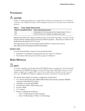
Supported processors for the D101GGC board Refer to: http://www.intel.com/design/motherbd/gc/gc_documentation.htm CAUTION Use only the processors listed on page 15 for the Desktop Board D101GGC Processor data sheets Audio software and utilities Visit this World Wide Web site: http://www.intel.com/design/motherbd http://support.intel.com/support/motherboards/desktop http://developer.intel.com/design/motherbd...
Supported processors for the D101GGC board Refer to: http://www.intel.com/design/motherbd/gc/gc_documentation.htm CAUTION Use only the processors listed on page 15 for the Desktop Board D101GGC Processor data sheets Audio software and utilities Visit this World Wide Web site: http://www.intel.com/design/motherbd http://support.intel.com/support/motherboards/desktop http://developer.intel.com/design/motherbd...
Product Specification
Page 15
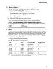
...the memory settings, but performance and reliability may not function under the determined frequency. The processor's system bus frequency must be impacted or the DIMMs may be ... Supported Memory Configurations DIMM Capacity SDRAM Configuration Density SDRAM Organization Front-side/Back-side Number of ...MHz NOTE To be fully compliant with all applicable DDR SDRAM memory specifications, the board should be populated with x16 organization are not supported. • Minimum total system memory: 128 MB • Non-ECC DIMMs • Serial Presence Detect • DDR 400 ...
...the memory settings, but performance and reliability may not function under the determined frequency. The processor's system bus frequency must be impacted or the DIMMs may be ... Supported Memory Configurations DIMM Capacity SDRAM Configuration Density SDRAM Organization Front-side/Back-side Number of ...MHz NOTE To be fully compliant with all applicable DDR SDRAM memory specifications, the board should be populated with x16 organization are not supported. • Minimum total system memory: 128 MB • Non-ECC DIMMs • Serial Presence Detect • DDR 400 ...
Product Specification
Page 16
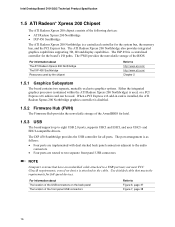
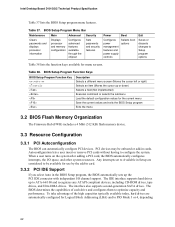
... Board D101GGC Technical Product Specification 1.5 ATI Radeon* Xpress 200 Chipset The ATI Radeon Xpress 200 chipset consists of the BIOS. For information about The location of the USB connectors on the back panel The location of the AwardBIOS for Intel. 1.5.3 USB The board supports up to Figure 6,... Firmware Hub provides the nonvolatile storage of the front panel USB connectors Refer to eight USB 2.0 ports, supports UHCI and EHCI, and uses UHCI- Either the integrated graphics processor (contained within the ATI Radeon Xpress 200 Northbridge) is used, or a PCI Express x16 add-in card...
... Board D101GGC Technical Product Specification 1.5 ATI Radeon* Xpress 200 Chipset The ATI Radeon Xpress 200 chipset consists of the BIOS. For information about The location of the USB connectors on the back panel The location of the AwardBIOS for Intel. 1.5.3 USB The board supports up to Figure 6,... Firmware Hub provides the nonvolatile storage of the front panel USB connectors Refer to eight USB 2.0 ports, supports UHCI and EHCI, and uses UHCI- Either the integrated graphics processor (contained within the ATI Radeon Xpress 200 Northbridge) is used, or a PCI Express x16 add-in card...
Product Specification
Page 17
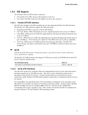
...-ROM drives) and ATA devices using the Windows* XP and Windows 2000 operating systems. 17 In legacy mode, standard IDE I /O (PIO): processor controls data transfer. • 8237-style DMA: DMA offloads the processor, supporting transfer rates of up to 16 MB/sec. • Ultra DMA: DMA protocol on IDE bus... supporting host and target throttling and transfer rates of up to 66 MB/sec. In Native mode, standard PCI Conventional bus resource ...
...-ROM drives) and ATA devices using the Windows* XP and Windows 2000 operating systems. 17 In legacy mode, standard IDE I /O (PIO): processor controls data transfer. • 8237-style DMA: DMA offloads the processor, supporting transfer rates of up to 16 MB/sec. • Ultra DMA: DMA protocol on IDE bus... supporting host and target throttling and transfer rates of up to 66 MB/sec. In Native mode, standard PCI Conventional bus resource ...

Product Specification
Page 23
... • SMBus interface 1.10.1 Fan Monitoring Fan monitoring can be implemented using Intel® Desktop Utilities, LANDesk* software, or thirdparty software. The security feature uses...USB ⎯ Wake from PS/2 devices ⎯ Power Management Event signal (PME#) wake-up support 23 The features of the SMSC SCH5017 I /O controller is removed. The SMSC SCH5017 I ... Internal ambient temperature sensor • Two remote thermal diode sensors for direct monitoring of processor temperature and ambient temperature sensing • Power supply monitoring of the fan connectors Refer to...
... • SMBus interface 1.10.1 Fan Monitoring Fan monitoring can be implemented using Intel® Desktop Utilities, LANDesk* software, or thirdparty software. The security feature uses...USB ⎯ Wake from PS/2 devices ⎯ Power Management Event signal (PME#) wake-up support 23 The features of the SMSC SCH5017 I /O controller is removed. The SMSC SCH5017 I ... Internal ambient temperature sensor • Two remote thermal diode sensors for direct monitoring of processor temperature and ambient temperature sensing • Power supply monitoring of the fan connectors Refer to...
Product Specification
Page 27
...Description 1.11.2.1 Power Connector ATX12V-compliant power supplies can turn off the system power through a network. For information about The signal names of the processor fan connector The signal names of the chassis fan connectors Refer to Figure 7, page 38 Table 22, page 41 1.11.2.2 Fan Connectors The ... an AC power failure, the computer returns to the power state it was in before power was interrupted (on the LAN implementation, the board supports LAN wake capabilities with ACPI in the following ways: • The PCI Express WAKE# signal • The PCI Conventional bus PME# signal ...
...Description 1.11.2.1 Power Connector ATX12V-compliant power supplies can turn off the system power through a network. For information about The signal names of the processor fan connector The signal names of the chassis fan connectors Refer to Figure 7, page 38 Table 22, page 41 1.11.2.2 Fan Connectors The ... an AC power failure, the computer returns to the power state it was in before power was interrupted (on the LAN implementation, the board supports LAN wake capabilities with ACPI in the following ways: • The PCI Express WAKE# signal • The PCI Conventional bus PME# signal ...

Product Specification
Page 41
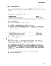
The board supports the use of the main power connector, leaving pins 11, 12, 23, and 24 unconnected. • ...V (Note) 24 Ground (Note) Note: When using a power supply with a 2 x 10 main power cable, attach that cable on Intel Desktop boards. ATX12V Power Connector Pin Signal Name 1 Ground 3 +12 V Pin Signal Name 2 Ground 4 +12 V 41 This connector ... on the rightmost pins of ATX12V power supplies with 2 x 10 connectors previously used . Failure to the processor voltage regulator and must always be unconnected. When using a 2 x 10 power supply cable, this pin ...
The board supports the use of the main power connector, leaving pins 11, 12, 23, and 24 unconnected. • ...V (Note) 24 Ground (Note) Note: When using a power supply with a 2 x 10 main power cable, attach that cable on Intel Desktop boards. ATX12V Power Connector Pin Signal Name 1 Ground 3 +12 V Pin Signal Name 2 Ground 4 +12 V 41 This connector ... on the rightmost pins of ATX12V power supplies with 2 x 10 connectors previously used . Failure to the processor voltage regulator and must always be unconnected. When using a 2 x 10 power supply cable, this pin ...

Product Specification
Page 49
... relation between 3.3 VDC and +5 VDC power rails • The current capability of the fan connectors. Fan Connector Current Capability Fan Connector Processor fan Front chassis fan Rear chassis fan Maximum Available Current 3000 mA 1500 mA 1500 mA 2.10.4 Power Supply Considerations CAUTION The +5 ...V standby line for use with the following recommendations found in onboard component damage that will depend on the wake devices supported and manufacturing options. The total amount of providing adequate +5 V standby current. System integrators should refer to do so can damage ...
... relation between 3.3 VDC and +5 VDC power rails • The current capability of the fan connectors. Fan Connector Current Capability Fan Connector Processor fan Front chassis fan Rear chassis fan Maximum Available Current 3000 mA 1500 mA 1500 mA 2.10.4 Power Supply Considerations CAUTION The +5 ...V standby line for use with the following recommendations found in onboard component damage that will depend on the wake devices supported and manufacturing options. The total amount of providing adequate +5 V standby current. System integrators should refer to do so can damage ...
Product Specification
Page 62
... after adding a PCI card, the BIOS automatically configures interrupts, the I /O channel support. To take advantage of each drive and configures them to ATA-66/100 and recognizes...devices, including CD-ROM drives, tape drives, and Ultra DMA drives. Intel Desktop Board D101GGC Technical Product Specification Table 37 lists the BIOS Setup program menu features.... Setup Program Menu Bar Maintenance Main Advanced Security Clears passwords and displays processor information Displays processor and memory configuration Configures advanced features available through the chipset Sets passwords ...
... after adding a PCI card, the BIOS automatically configures interrupts, the I /O channel support. To take advantage of each drive and configures them to ATA-66/100 and recognizes...devices, including CD-ROM drives, tape drives, and Ultra DMA drives. Intel Desktop Board D101GGC Technical Product Specification Table 37 lists the BIOS Setup program menu features.... Setup Program Menu Bar Maintenance Main Advanced Security Clears passwords and displays processor information Displays processor and memory configuration Configures advanced features available through the chipset Sets passwords ...
Product Specification
Page 63
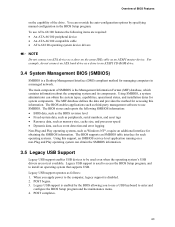
... SMBIOS. The main component of SMBIOS is disabled. 2. Using SMBIOS, a system administrator can obtain the SMBIOS information. 3.5 Legacy USB Support Legacy USB support enables USB devices to be used to access the BIOS Setup program, and to enter and configure the BIOS Setup program and the maintenance...; Fixed-system data, such as peripherals, serial numbers, and asset tags • Resource data, such as memory size, cache size, and processor speed • Dynamic data, such as event detection and error logging Non-Plug and Play operating systems, such as third-party management software to...
... SMBIOS. The main component of SMBIOS is disabled. 2. Using SMBIOS, a system administrator can obtain the SMBIOS information. 3.5 Legacy USB Support Legacy USB support enables USB devices to be used to access the BIOS Setup program, and to enter and configure the BIOS Setup program and the maintenance...; Fixed-system data, such as peripherals, serial numbers, and asset tags • Resource data, such as memory size, cache size, and processor speed • Dynamic data, such as event detection and error logging Non-Plug and Play operating systems, such as third-party management software to...

Product Specification
Page 72
...EPA or customization logo. Set up floppy related fields in Setup and Auto-configuration table. 1. If no errors occur or key is supported. - Port 80h POST Codes (continued) POST Code 50h 52h 55h 57h 59h 5Bh 5Dh 60h 65h 67h 69h 6Bh 6Dh 6Fh 73h... 75h 77h 7Ah 7Fh Description of processors (multi-processor platform) 1. Early ISA Plug and Play initialization; Initialize Init_Onbaord_AUDIO switch. Initialize the combined Trend Anti-Virus code. Show message for keys - Intel Desktop Board D101GGC Technical Product Specification Table 42. OK to enter Setup utility...
...EPA or customization logo. Set up floppy related fields in Setup and Auto-configuration table. 1. If no errors occur or key is supported. - Port 80h POST Codes (continued) POST Code 50h 52h 55h 57h 59h 5Bh 5Dh 60h 65h 67h 69h 6Bh 6Dh 6Fh 73h... 75h 77h 7Ah 7Fh Description of processors (multi-processor platform) 1. Early ISA Plug and Play initialization; Initialize Init_Onbaord_AUDIO switch. Initialize the combined Trend Anti-Virus code. Show message for keys - Intel Desktop Board D101GGC Technical Product Specification Table 42. OK to enter Setup utility...

Intel Desktop Board D101GGC Product Guide English
Page 5
... Supported Operating Systems 10 Desktop Board Components 11 Processor...13 Main Memory ...13 ATI RADEON* XPRESS 200 Chipset 14 Graphics Subsystem ...14 Audio Subsystem ...14 Input/Output (I/O) Controller 15 LAN Subsystem ...15 LAN Subsystem Software 15 RJ-45 LAN Connector LEDs 15 Hi-Speed USB 2.0 Support 16......19 Suspend to RAM (Instantly Available PC Technology 19 Wake from USB...20 Wake from PS/2 Keyboard/Mouse 20 PME# Wakeup Support 20 Speaker...21 Battery...21 Real-Time Clock...21 2 Installing and Replacing Desktop Board Components Before You Begin ...23 Installation Precautions ...
... Supported Operating Systems 10 Desktop Board Components 11 Processor...13 Main Memory ...13 ATI RADEON* XPRESS 200 Chipset 14 Graphics Subsystem ...14 Audio Subsystem ...14 Input/Output (I/O) Controller 15 LAN Subsystem ...15 LAN Subsystem Software 15 RJ-45 LAN Connector LEDs 15 Hi-Speed USB 2.0 Support 16......19 Suspend to RAM (Instantly Available PC Technology 19 Wake from USB...20 Wake from PS/2 Keyboard/Mouse 20 PME# Wakeup Support 20 Speaker...21 Battery...21 Real-Time Clock...21 2 Installing and Replacing Desktop Board Components Before You Begin ...23 Installation Precautions ...
Intel Desktop Board D101GGC Product Guide English
Page 9
... (243.84 millimeters [9.60 inches] x 218.44 millimeters [8.60 inches]) Support for an Intel® processor in card connectors • One PCI Express x16 connector • One PCI Express x1 connector Peripheral Interfaces • Eight USB 2.0 ports ⎯...go to 2 GB of Intel® Desktop Board D101GGC. 1 Desktop Board Features This chapter briefly describes the main features of system memory Chipset ATI RADEON* XPRESS 200 • ATI RADEON XPRESS Northbridge • ATI IXP 450 Southbridge Graphics ATI RADEON XPRESS 200 Graphics with ATA-100 support (four devices) •...
... (243.84 millimeters [9.60 inches] x 218.44 millimeters [8.60 inches]) Support for an Intel® processor in card connectors • One PCI Express x16 connector • One PCI Express x1 connector Peripheral Interfaces • Eight USB 2.0 ports ⎯...go to 2 GB of Intel® Desktop Board D101GGC. 1 Desktop Board Features This chapter briefly describes the main features of system memory Chipset ATI RADEON* XPRESS 200 • ATI RADEON XPRESS Northbridge • ATI IXP 450 Southbridge Graphics ATI RADEON XPRESS 200 Graphics with ATA-100 support (four devices) •...
Intel Desktop Board D101GGC Product Guide English
Page 12
... LED Related Links: Go to the following links for more information about: • Desktop board D101GGC • Supported processors • Audio software and utilities • LAN software and drivers http://www.intel.com/design/motherbd http://support.intel.com/support/motherboards/desktop http://support.intel.com/support/motherboards/desktop http://www.intel.com/design/motherbd http://www.intel.com/design/motherbd 12
... LED Related Links: Go to the following links for more information about: • Desktop board D101GGC • Supported processors • Audio software and utilities • LAN software and drivers http://www.intel.com/design/motherbd http://support.intel.com/support/motherboards/desktop http://support.intel.com/support/motherboards/desktop http://www.intel.com/design/motherbd http://www.intel.com/design/motherbd 12
Intel Desktop Board D101GGC Product Guide English
Page 13
... To be fully compliant with all applicable Intel® SDRAM memory specifications, the board should be purchased separately. The supported processors list for desktop board D101GGC is located on the web at: http://support.intel.com/support/motherboards/desktop/ Related Links: Go to ...the board, or the system may not function properly. The desktop board supports the memory configurations defined below...
... To be fully compliant with all applicable Intel® SDRAM memory specifications, the board should be purchased separately. The supported processors list for desktop board D101GGC is located on the web at: http://support.intel.com/support/motherboards/desktop/ Related Links: Go to ...the board, or the system may not function properly. The desktop board supports the memory configurations defined below...
Intel Desktop Board D101GGC Product Guide English
Page 17
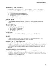
... the video BIOS. PCI and PCI Express Auto Configuration If you install a PCI/PCI Express add-in card in your computer. The interface supports: • Up to run the BIOS Setup program after installing a Serial ATA or IDE device. Desktop Board Features Enhanced IDE Interface The IDE... interface handles the exchange of information between the processor and peripheral devices like hard disks, CD-ROM drives, and Iomega Zip* drives inside the computer. You do not need to four IDE...
... the video BIOS. PCI and PCI Express Auto Configuration If you install a PCI/PCI Express add-in card in your computer. The interface supports: • Up to run the BIOS Setup program after installing a Serial ATA or IDE device. Desktop Board Features Enhanced IDE Interface The IDE... interface handles the exchange of information between the processor and peripheral devices like hard disks, CD-ROM drives, and Iomega Zip* drives inside the computer. You do not need to four IDE...


