
Product Specification
Page 1
Current characterized errata are documented in the Intel Desktop Board D101GGC Specification Update. Intel® Desktop Board D101GGC Technical Product Specification November 2005 Order Number: D36105-002US The Intel® Desktop Board D101GGC may contain design defects or errors known as errata that may cause the product to deviate from published specifications.
Current characterized errata are documented in the Intel Desktop Board D101GGC Specification Update. Intel® Desktop Board D101GGC Technical Product Specification November 2005 Order Number: D36105-002US The Intel® Desktop Board D101GGC may contain design defects or errors known as errata that may cause the product to deviate from published specifications.
Product Specification
Page 2
... OR INFRINGEMENT OF ANY PATENT, COPYRIGHT OR OTHER INTELLECTUAL PROPERTY RIGHT. Contact your local Intel sales office or your distributor to only standard Intel Desktop Board D101GGC with BIOS identifier GC11010N.86A. The furnishing of this document. Copies of any time,... -001 -002 Revision History First release of the Intel® Desktop Board D101GGC Technical Product Specification. Second release of the Intel® Desktop Board D101GGC Technical Product Specification. Copyright © 2005, Intel Corporation. INTEL PRODUCTS ARE NOT INTENDED FOR USE IN MEDICAL, LIFE...
... OR INFRINGEMENT OF ANY PATENT, COPYRIGHT OR OTHER INTELLECTUAL PROPERTY RIGHT. Contact your local Intel sales office or your distributor to only standard Intel Desktop Board D101GGC with BIOS identifier GC11010N.86A. The furnishing of this document. Copies of any time,... -001 -002 Revision History First release of the Intel® Desktop Board D101GGC Technical Product Specification. Second release of the Intel® Desktop Board D101GGC Technical Product Specification. Copyright © 2005, Intel Corporation. INTEL PRODUCTS ARE NOT INTENDED FOR USE IN MEDICAL, LIFE...
Product Specification
Page 3
Intended Audience The TPS is specifically not intended for the Intel® Desktop Board D101GGC. Not all of these symbols and abbreviations appear in this type. Notes, Cautions, and Warnings NOTE Notes call attention to information that may be ... requirements, and the BIOS for general audiences. CAUTION Cautions are used on the Desktop Board D101GGC A map of the resources of the Desktop Board Typographical Conventions This section contains information about the Desktop Board D101GGC and its components to the vendors, system integrators, and other engineers and technicians who need ...
Intended Audience The TPS is specifically not intended for the Intel® Desktop Board D101GGC. Not all of these symbols and abbreviations appear in this type. Notes, Cautions, and Warnings NOTE Notes call attention to information that may be ... requirements, and the BIOS for general audiences. CAUTION Cautions are used on the Desktop Board D101GGC A map of the resources of the Desktop Board Typographical Conventions This section contains information about the Desktop Board D101GGC and its components to the vendors, system integrators, and other engineers and technicians who need ...
Product Specification
Page 4
... example, J5J1 is the instance of a component, N indicates component type, xn are DC unless otherwise specified. Volts. It is used in the 5J area. Intel Desktop Board D101GGC Technical Product Specification Other Common Notation # (NxnX) GB GB/sec KB Kbit kbits/sec MB MB/sec Mbit Mbit/sec xxh x.x V * Used after a signal...
... example, J5J1 is the instance of a component, N indicates component type, xn are DC unless otherwise specified. Volts. It is used in the 5J area. Intel Desktop Board D101GGC Technical Product Specification Other Common Notation # (NxnX) GB GB/sec KB Kbit kbits/sec MB MB/sec Mbit Mbit/sec xxh x.x V * Used after a signal...
Product Specification
Page 5
Contents 1 Product Description 1.1 Overview ...10 1.1.1 Feature Summary 10 1.1.2 Block Diagram 11 1.1.3 Board Layout 12 1.2 Online Support ...14 1.3 Processor ...14 1.4 System Memory ...15 1.5 ATI Radeon* Xpress 200 Chipset 16 1.5.1 Graphics Subsystem 16 1.5.2 Firmware Hub (FWH 16 1.5.3 USB ...16 1.5.4 IDE Support 17 1.5.5 Real-Time Clock, CMOS SRAM, and Battery 18 1.6 PCI Express* Connectors 18 1.7 Legacy I/O Controller 19 1.7.1 Serial Port...19 1.7.2 Parallel Port 19 1.7.3 Diskette Drive Controller 19 1.7.4 Keyboard and Mouse Interface 19 1.8 High Definition Audio Subsystem 20 ...
Contents 1 Product Description 1.1 Overview ...10 1.1.1 Feature Summary 10 1.1.2 Block Diagram 11 1.1.3 Board Layout 12 1.2 Online Support ...14 1.3 Processor ...14 1.4 System Memory ...15 1.5 ATI Radeon* Xpress 200 Chipset 16 1.5.1 Graphics Subsystem 16 1.5.2 Firmware Hub (FWH 16 1.5.3 USB ...16 1.5.4 IDE Support 17 1.5.5 Real-Time Clock, CMOS SRAM, and Battery 18 1.6 PCI Express* Connectors 18 1.7 Legacy I/O Controller 19 1.7.1 Serial Port...19 1.7.2 Parallel Port 19 1.7.3 Diskette Drive Controller 19 1.7.4 Keyboard and Mouse Interface 19 1.8 High Definition Audio Subsystem 20 ...
Product Specification
Page 6
Intel Desktop Board D101GGC Technical Product Specification 2.9 Mechanical Considerations 46 2.9.1 Form Factor 46 2.9.2 I/O Shield...47 2.10 Electrical Considerations 48 2.10.1 DC Loading...48 2.10.2 Add-in Board Considerations 48 2....
Intel Desktop Board D101GGC Technical Product Specification 2.9 Mechanical Considerations 46 2.9.1 Form Factor 46 2.9.2 I/O Shield...47 2.10 Electrical Considerations 48 2.10.1 DC Loading...48 2.10.2 Add-in Board Considerations 48 2....

Product Specification
Page 7
LAN Connector LED Locations 22 5. Location of the Jumper Block 45 11. Board Dimensions...46 12. Feature Summary ...10 2. Supported Memory Configurations 15 5. Power States and Targeted System Power 25 8. PCI Configuration Space Map 35 14. PCI Interrupt Routing Map 35 15. Chassis Intrusion Connector 40 19. Chassis Fan Connectors 40 22. DC Loading Characteristics 48 30. Thermal Considerations for High Definition Audio Subsystem...... 21 4. Front/Back Panel Audio Connector Options for Components 52 vii Connection Diagram for a Two-Color Power LED 43 28. Serial...
LAN Connector LED Locations 22 5. Location of the Jumper Block 45 11. Board Dimensions...46 12. Feature Summary ...10 2. Supported Memory Configurations 15 5. Power States and Targeted System Power 25 8. PCI Configuration Space Map 35 14. PCI Interrupt Routing Map 35 15. Chassis Intrusion Connector 40 19. Chassis Fan Connectors 40 22. DC Loading Characteristics 48 30. Thermal Considerations for High Definition Audio Subsystem...... 21 4. Front/Back Panel Audio Connector Options for Components 52 vii Connection Diagram for a Two-Color Power LED 43 28. Serial...
Product Specification
Page 9
1 Product Description What This Chapter Contains 1.1 Overview ...10 1.2 Online Support ...14 1.3 Processor ...14 1.4 System Memory ...15 1.5 ATI Radeon* Xpress 200 Chipset 16 1.6 PCI Express* Connectors 18 1.7 Legacy I/O Controller 19 1.8 High Definition Audio Subsystem 20 1.9 LAN Subsystem ...22 1.10 Hardware Management Subsystem 23 1.11 Power Management ...23 9
1 Product Description What This Chapter Contains 1.1 Overview ...10 1.2 Online Support ...14 1.3 Processor ...14 1.4 System Memory ...15 1.5 ATI Radeon* Xpress 200 Chipset 16 1.6 PCI Express* Connectors 18 1.7 Legacy I/O Controller 19 1.8 High Definition Audio Subsystem 20 1.9 LAN Subsystem ...22 1.10 Hardware Management Subsystem 23 1.11 Power Management ...23 9
Product Specification
Page 10
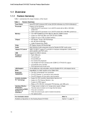
Intel Desktop Board D101GGC Technical Product Specification 1.1 Overview 1.1.1 Feature Summary Table 1 summarizes the major features of range thermal values • Three fan connectors • Three fan sense inputs used to monitor fan activity • Fan speed control For information about Available configurations for the Desktop Board D101GGC... • PS/2 keyboard and mouse ports 10/100 Mbits/sec LAN subsystem using the Realtek 8101L LAN adapter device AwardBIOS* for Intel® resident in the 4 Mbit FWH • Two PCI Conventional* bus connectors • One PCI Express* x1 bus add...
Intel Desktop Board D101GGC Technical Product Specification 1.1 Overview 1.1.1 Feature Summary Table 1 summarizes the major features of range thermal values • Three fan connectors • Three fan sense inputs used to monitor fan activity • Fan speed control For information about Available configurations for the Desktop Board D101GGC... • PS/2 keyboard and mouse ports 10/100 Mbits/sec LAN subsystem using the Realtek 8101L LAN adapter device AwardBIOS* for Intel® resident in the 4 Mbit FWH • Two PCI Conventional* bus connectors • One PCI Express* x1 bus add...
Product Specification
Page 11
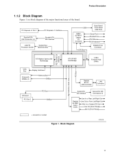
Product Description 1.1.2 Block Diagram Figure 1 is a block diagram of the major functional areas of the board. Block Diagram OM18245 11 PCI Express x1 Slot 1 PCI Express x1 Interface Parallel ATA IDE Connectors (2) Parallel ATA IDE Interface LGA775 Processor Socket System Bus (800/533 MHz) USB Back Panel/ Front Panel USB Ports SMSC SCH5017 Legacy I/O Controller LPC Bus Serial Port Parallel Port PS/2 Mouse PS/2 Keyboard Diskette Drive Connector PCI Express x4 Interface High Definition Audio Link PCI Bus ATI Radeon Xpress 200 Northbridge ATI IXP 450 Southbridge 4 Mbit Firmware ...
Product Description 1.1.2 Block Diagram Figure 1 is a block diagram of the major functional areas of the board. Block Diagram OM18245 11 PCI Express x1 Slot 1 PCI Express x1 Interface Parallel ATA IDE Connectors (2) Parallel ATA IDE Interface LGA775 Processor Socket System Bus (800/533 MHz) USB Back Panel/ Front Panel USB Ports SMSC SCH5017 Legacy I/O Controller LPC Bus Serial Port Parallel Port PS/2 Mouse PS/2 Keyboard Diskette Drive Connector PCI Express x4 Interface High Definition Audio Link PCI Bus ATI Radeon Xpress 200 Northbridge ATI IXP 450 Southbridge 4 Mbit Firmware ...
Product Specification
Page 12
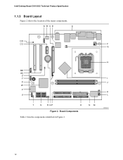
Intel Desktop Board D101GGC Technical Product Specification 1.1.3 Board Layout Figure 2 shows the location of the major components. Board Components Table 2 lists the components identified in Figure 2. NM OM18247 12 A B CD E DD CC F G H BB AA Z Y I X J W V K U L T S RQP O Figure 2.
Intel Desktop Board D101GGC Technical Product Specification 1.1.3 Board Layout Figure 2 shows the location of the major components. Board Components Table 2 lists the components identified in Figure 2. NM OM18247 12 A B CD E DD CC F G H BB AA Z Y I X J W V K U L T S RQP O Figure 2.

Product Specification
Page 13
Board Components Shown in Figure 2 Item/callout from Figure 2 Description A Front panel audio connector B Audio codec C PCI Express x16 add-in card connector D Ethernet device E Back panel connectors F +12V power connector (ATX12V) G Rear chassis fan connector H LGA775 processor socket I ATI Radeon Xpress 200 Northbridge J DIMM Channel A sockets [2] K Processor fan connector L Chassis intrusion connector M Legacy I/O controller N Main power connector O Diskette drive connector P Parallel ATE IDE connectors [2] Q Battery R Front chassis fan connector S ...
Board Components Shown in Figure 2 Item/callout from Figure 2 Description A Front panel audio connector B Audio codec C PCI Express x16 add-in card connector D Ethernet device E Back panel connectors F +12V power connector (ATX12V) G Rear chassis fan connector H LGA775 processor socket I ATI Radeon Xpress 200 Northbridge J DIMM Channel A sockets [2] K Processor fan connector L Chassis intrusion connector M Legacy I/O controller N Main power connector O Diskette drive connector P Parallel ATE IDE connectors [2] Q Battery R Front chassis fan connector S ...
Product Specification
Page 14
... supplies. • Refer to Section 2.7.2.1, page 41 14 For information about ... Use of supported system bus frequency and memory speed combinations. Supported processors for the D101GGC board Refer to: http://www.intel.com/design/motherbd/gc/gc_documentation.htm CAUTION Use only the processors listed on page 15 for the Desktop Board...
... supplies. • Refer to Section 2.7.2.1, page 41 14 For information about ... Use of supported system bus frequency and memory speed combinations. Supported processors for the D101GGC board Refer to: http://www.intel.com/design/motherbd/gc/gc_documentation.htm CAUTION Use only the processors listed on page 15 for the Desktop Board...
Product Specification
Page 15
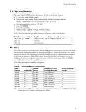
DDR 400 800 MHz DDR 333 800 or 533 MHz NOTE To be fully compliant with all applicable DDR SDRAM memory specifications, the board should be populated with x16 organization are not supported. • Minimum total system memory: 128 MB • Non-ECC DIMMs • Serial Presence Detect • DDR 400 MHz and DDR 333 MHz SDRAM DIMMs Table 3 lists the supported system bus frequency and memory speed combinations. This allows the BIOS to read the SPD data and program the chipset to single-sided memory modules (containing one row of SDRAM). 15 Table 4 lists the supported DIMM configurations...
DDR 400 800 MHz DDR 333 800 or 533 MHz NOTE To be fully compliant with all applicable DDR SDRAM memory specifications, the board should be populated with x16 organization are not supported. • Minimum total system memory: 128 MB • Non-ECC DIMMs • Serial Presence Detect • DDR 400 MHz and DDR 333 MHz SDRAM DIMMs Table 3 lists the supported system bus frequency and memory speed combinations. This allows the BIOS to read the SPD data and program the chipset to single-sided memory modules (containing one row of SDRAM). 15 Table 4 lists the supported DIMM configurations...
Product Specification
Page 16
... device is disabled. 1.5.2 Firmware Hub (FWH) The Firmware Hub provides the nonvolatile storage of the AwardBIOS for full-speed devices. Intel Desktop Board D101GGC Technical Product Specification 1.5 ATI Radeon* Xpress 200 Chipset The ATI Radeon Xpress 200 chipset consists of the following devices: • ...audio connectors • Four ports are routed to two separate front panel USB connectors NOTE Computer systems that meets the requirements for Intel. 1.5.3 USB The board supports up to the cable. The port arrangement is a centralized controller for the system bus, the ...
... device is disabled. 1.5.2 Firmware Hub (FWH) The Firmware Hub provides the nonvolatile storage of the AwardBIOS for full-speed devices. Intel Desktop Board D101GGC Technical Product Specification 1.5 ATI Radeon* Xpress 200 Chipset The ATI Radeon Xpress 200 chipset consists of the following devices: • ...audio connectors • Four ports are routed to two separate front panel USB connectors NOTE Computer systems that meets the requirements for Intel. 1.5.3 USB The board supports up to the cable. The port arrangement is a centralized controller for the system bus, the ...
Product Specification
Page 17
The Parallel ATA IDE interfaces also support ATAPI devices (such as CD-ROM drives) and ATA devices using the Windows* XP and Windows 2000 operating systems. 17 For compatibility, the underlying Serial ATA functionality is device driver compatible. • ATA-100: DMA protocol on IDE bus allows host and target throttling. The Serial ATA controller can achieve read transfer rates up to 100 MB/sec and write transfer rates up to 66 MB/sec. In legacy mode, standard IDE I /O (PIO): processor controls data transfer. • 8237-style DMA: DMA offloads the processor, supporting ...
The Parallel ATA IDE interfaces also support ATAPI devices (such as CD-ROM drives) and ATA devices using the Windows* XP and Windows 2000 operating systems. 17 For compatibility, the underlying Serial ATA functionality is device driver compatible. • ATA-100: DMA protocol on IDE bus allows host and target throttling. The Serial ATA controller can achieve read transfer rates up to 100 MB/sec and write transfer rates up to 66 MB/sec. In legacy mode, standard IDE I /O (PIO): processor controls data transfer. • 8237-style DMA: DMA offloads the processor, supporting ...
Product Specification
Page 18
Intel Desktop Board D101GGC Technical Product Specification NOTE Many Serial ATA drives use new low-voltage power connectors and require adaptors or power supplies equipped with 3.3 VSB applied. The ...
Intel Desktop Board D101GGC Technical Product Specification NOTE Many Serial ATA drives use new low-voltage power connectors and require adaptors or power supplies equipped with 3.3 VSB applied. The ...
Product Specification
Page 19
For information about The location of the parallel port connector Refer to 115.2 kbits/sec with serialized IRQ support for PCI Conventional bus systems • PS/2-style mouse and keyboard interfaces • Interface for the I/O controller. 1.7.1 Serial Port The Serial port A connector is connected or disconnected. Power to set the parallel port mode. Use the BIOS Setup program to the computer should be turned off before a keyboard or mouse is located on the back panel. The serial port supports data transfers at speeds up to Figure 6, page 37 1.7.3 Diskette Drive ...
For information about The location of the parallel port connector Refer to 115.2 kbits/sec with serialized IRQ support for PCI Conventional bus systems • PS/2-style mouse and keyboard interfaces • Interface for the I/O controller. 1.7.1 Serial Port The Serial port A connector is connected or disconnected. Power to set the parallel port mode. Use the BIOS Setup program to the computer should be turned off before a keyboard or mouse is located on the back panel. The serial port supports data transfers at speeds up to Figure 6, page 37 1.7.3 Diskette Drive ...

Product Specification
Page 20
Intel Desktop Board D101GGC Technical Product Specification 1.8 High Definition Audio Subsystem The board includes a flexible 6-channel audio subsystem based on an Intel® High Definition Audio interface. For information about Obtaining audio software and drivers Refer to function, a front panel daughter card ... used. The audio subsystem features: • ATI IXP 450 Southbridge • Realtek ALC861 audio codec • Impedance sensing capability for Intel High Definition Audio must be permanent. 1.8.1 Audio Subsystem Software Audio software and drivers are available from...
Intel Desktop Board D101GGC Technical Product Specification 1.8 High Definition Audio Subsystem The board includes a flexible 6-channel audio subsystem based on an Intel® High Definition Audio interface. For information about Obtaining audio software and drivers Refer to function, a front panel daughter card ... used. The audio subsystem features: • ATI IXP 450 Southbridge • Realtek ALC861 audio codec • Impedance sensing capability for Intel High Definition Audio must be permanent. 1.8.1 Audio Subsystem Software Audio software and drivers are available from...

Product Specification
Page 21
The audio subsystem connectors are shown in and line out signals for High Definition Audio Subsystem For information about The location of the front panel audio connector The signal names of the board. Front Panel Audio Connectors Back Panel Audio Connectors Line Out Mic In Line In or Rear Left/Right Out Line Out or Front Left/Right Out Mic In or Center/LFE (Subwoofer) Out OM18246 Figure 3. Product Description 1.8.2 Audio Connectors The board contains audio connector on both the back panel and the component side of the front panel audio connector The back panel audio connectors ...
The audio subsystem connectors are shown in and line out signals for High Definition Audio Subsystem For information about The location of the front panel audio connector The signal names of the board. Front Panel Audio Connectors Back Panel Audio Connectors Line Out Mic In Line In or Rear Left/Right Out Line Out or Front Left/Right Out Mic In or Center/LFE (Subwoofer) Out OM18246 Figure 3. Product Description 1.8.2 Audio Connectors The board contains audio connector on both the back panel and the component side of the front panel audio connector The back panel audio connectors ...
