
Product Specification
Page 5
... Overview ...10 1.1.1 Feature Summary 10 1.1.2 Block Diagram 11 1.1.3 Board Layout 12 1.2 Online Support ...14 1.3 Processor ...14 1.4 System Memory ...15 1.5 ATI Radeon* Xpress 200 Chipset 16 1.5.1 Graphics Subsystem 16 1.5.2 Firmware Hub (FWH 16 1.5.3 USB ...16 1.5.4 IDE Support ... 23 1.10.2 Chassis Intrusion and Detection 23 1.11 Power Management ...23 1.11.1 ACPI ...24 1.11.2 Hardware Support 26 2 Technical Reference 2.1 Memory Map ...31 2.2 DMA Channels ...32 2.3 Fixed I/O Map...33 2.4 Interrupts ...34 2.5 PCI Configuration Space Map 35 2.6 PCI Conventional Interrupt Routing ...
... Overview ...10 1.1.1 Feature Summary 10 1.1.2 Block Diagram 11 1.1.3 Board Layout 12 1.2 Online Support ...14 1.3 Processor ...14 1.4 System Memory ...15 1.5 ATI Radeon* Xpress 200 Chipset 16 1.5.1 Graphics Subsystem 16 1.5.2 Firmware Hub (FWH 16 1.5.3 USB ...16 1.5.4 IDE Support ... 23 1.10.2 Chassis Intrusion and Detection 23 1.11 Power Management ...23 1.11.1 ACPI ...24 1.11.2 Hardware Support 26 2 Technical Reference 2.1 Memory Map ...31 2.2 DMA Channels ...32 2.3 Fixed I/O Map...33 2.4 Interrupts ...34 2.5 PCI Configuration Space Map 35 2.6 PCI Conventional Interrupt Routing ...
Product Specification
Page 6
Intel Desktop Board D101GGC Technical Product Specification 2.9 Mechanical Considerations 46 2.9.1 Form Factor 46 2.9.2 I/O Shield...47 2.10 Electrical Considerations 48 2.10.1 DC Loading...48 2.10.2 Add-in ...2.14.3 Product Ecology Statements 56 2.14.4 EMC Regulations 59 2.14.5 Product Certification Markings (Board Level 60 3 Overview of BIOS Features 3.1 Introduction ...61 3.2 BIOS Flash Memory Organization 62 3.3 Resource Configuration 62 3.3.1 PCI Autoconfiguration 62 3.3.2 PCI IDE Support 62 3.4 System Management BIOS (SMBIOS 63 3.5 Legacy USB Support...63 3.6 BIOS Updates ...64...
Intel Desktop Board D101GGC Technical Product Specification 2.9 Mechanical Considerations 46 2.9.1 Form Factor 46 2.9.2 I/O Shield...47 2.10 Electrical Considerations 48 2.10.1 DC Loading...48 2.10.2 Add-in ...2.14.3 Product Ecology Statements 56 2.14.4 EMC Regulations 59 2.14.5 Product Certification Markings (Board Level 60 3 Overview of BIOS Features 3.1 Introduction ...61 3.2 BIOS Flash Memory Organization 62 3.3 Resource Configuration 62 3.3.1 PCI Autoconfiguration 62 3.3.2 PCI IDE Support 62 3.4 System Management BIOS (SMBIOS 63 3.5 Legacy USB Support...63 3.6 BIOS Updates ...64...

Product Specification
Page 7
...Front Panel Connector 43 9. Interrupts ...34 13. BIOS Setup Configuration Jumper Settings 45 29. Location of Pressing the Power Switch 24 7. Supported Memory Configurations 15 5. I /O Shield Dimensions 47 13. Board Components Shown in Figure 2 13 3. Power States and Targeted System Power 25 ...ATX12V Power Connector 41 24. Auxiliary Front Panel Power/Sleep LED Connector 42 25. Connection Diagram for Components 52 vii System Memory Map 31 10. PCI Interrupt Routing Map 35 15. Chassis Intrusion Connector 40 19. Chassis Fan Connectors 40 22. ...
...Front Panel Connector 43 9. Interrupts ...34 13. BIOS Setup Configuration Jumper Settings 45 29. Location of Pressing the Power Switch 24 7. Supported Memory Configurations 15 5. I /O Shield Dimensions 47 13. Board Components Shown in Figure 2 13 3. Power States and Targeted System Power 25 ...ATX12V Power Connector 41 24. Auxiliary Front Panel Power/Sleep LED Connector 42 25. Connection Diagram for Components 52 vii System Memory Map 31 10. PCI Interrupt Routing Map 35 15. Chassis Intrusion Connector 40 19. Chassis Fan Connectors 40 22. ...
Product Specification
Page 9
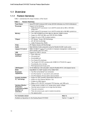
1 Product Description What This Chapter Contains 1.1 Overview ...10 1.2 Online Support ...14 1.3 Processor ...14 1.4 System Memory ...15 1.5 ATI Radeon* Xpress 200 Chipset 16 1.6 PCI Express* Connectors 18 1.7 Legacy I/O Controller 19 1.8 High Definition Audio Subsystem 20 1.9 LAN Subsystem ...22 1.10 Hardware Management Subsystem 23 1.11 Power Management ...23 9
1 Product Description What This Chapter Contains 1.1 Overview ...10 1.2 Online Support ...14 1.3 Processor ...14 1.4 System Memory ...15 1.5 ATI Radeon* Xpress 200 Chipset 16 1.6 PCI Express* Connectors 18 1.7 Legacy I/O Controller 19 1.8 High Definition Audio Subsystem 20 1.9 LAN Subsystem ...22 1.10 Hardware Management Subsystem 23 1.11 Power Management ...23 9
Product Specification
Page 10
...fan activity • Fan speed control For information about Available configurations for the Desktop Board D101GGC Refer to detect out of the board. Table 1. Feature Summary Form Factor Processor Memory Chipset Video Audio Legacy I/O Control USB Peripheral Interfaces LAN Support BIOS Expansion Capabilities Instantly ...drive interface • PS/2 keyboard and mouse ports 10/100 Mbits/sec LAN subsystem using the Realtek 8101L LAN adapter device AwardBIOS* for Intel® resident in the 4 Mbit FWH • Two PCI Conventional* bus connectors • One PCI Express* x1 bus add-in card...
...fan activity • Fan speed control For information about Available configurations for the Desktop Board D101GGC Refer to detect out of the board. Table 1. Feature Summary Form Factor Processor Memory Chipset Video Audio Legacy I/O Control USB Peripheral Interfaces LAN Support BIOS Expansion Capabilities Instantly ...drive interface • PS/2 keyboard and mouse ports 10/100 Mbits/sec LAN subsystem using the Realtek 8101L LAN adapter device AwardBIOS* for Intel® resident in the 4 Mbit FWH • Two PCI Conventional* bus connectors • One PCI Express* x1 bus add-in card...
Product Specification
Page 11
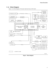
... High Definition Audio Link PCI Bus ATI Radeon Xpress 200 Northbridge ATI IXP 450 Southbridge 4 Mbit Firmware Hub (FWH) VGA Port Display Interface Channel A DIMMs (2) Memory Bus SMBus Realtek 8101L LAN Controller LAN Connector PCI Slot 1 PCI Slot 2 PCI Bus SMBus Serial ATA IDE Interface Serial ATA IDE Connectors (4) Realtek ALC861...
... High Definition Audio Link PCI Bus ATI Radeon Xpress 200 Northbridge ATI IXP 450 Southbridge 4 Mbit Firmware Hub (FWH) VGA Port Display Interface Channel A DIMMs (2) Memory Bus SMBus Realtek 8101L LAN Controller LAN Connector PCI Slot 1 PCI Slot 2 PCI Bus SMBus Serial ATA IDE Interface Serial ATA IDE Connectors (4) Realtek ALC861...
Product Specification
Page 14
... about Power supply connectors Refer to Section 2.7.2.1, page 41 14 For information about ... Use of supported system bus frequency and memory speed combinations. Supported processors for the D101GGC board Refer to: http://www.intel.com/design/motherbd/gc/gc_documentation.htm CAUTION Use only the processors listed on page 15 for the Desktop Board...
... about Power supply connectors Refer to Section 2.7.2.1, page 41 14 For information about ... Use of supported system bus frequency and memory speed combinations. Supported processors for the D101GGC board Refer to: http://www.intel.com/design/motherbd/gc/gc_documentation.htm CAUTION Use only the processors listed on page 15 for the Desktop Board...
Product Specification
Page 15
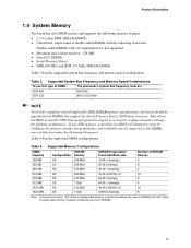
...MHz and DDR 333 MHz SDRAM DIMMs Table 3 lists the supported system bus frequency and memory speed combinations. Product Description 1.4 System Memory The board has two DIMM sockets and supports the following memory features: • 2.5 V (only) DDR SDRAM DIMMs • Unbuffered, single-... DIMMS with DIMMs that support the Serial Presence Detect (SPD) data structure. Table 4 lists the supported DIMM configurations. Supported Memory Configurations DIMM Capacity SDRAM Configuration Density SDRAM Organization Front-side/Back-side Number of SDRAM Devices 128 MB SS 256 Mbit 16 ...
...MHz and DDR 333 MHz SDRAM DIMMs Table 3 lists the supported system bus frequency and memory speed combinations. Product Description 1.4 System Memory The board has two DIMM sockets and supports the following memory features: • 2.5 V (only) DDR SDRAM DIMMs • Unbuffered, single-... DIMMS with DIMMs that support the Serial Presence Detect (SPD) data structure. Table 4 lists the supported DIMM configurations. Supported Memory Configurations DIMM Capacity SDRAM Configuration Density SDRAM Organization Front-side/Back-side Number of SDRAM Devices 128 MB SS 256 Mbit 16 ...
Product Specification
Page 16
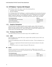
.... When a PCI Express x16 add-in card can be used. The IXP 450 is a centralized controller for the system bus, the memory bus, and the PCI Express bus. and EHCI-compatible drivers. The port arrangement is as follows: • Four ports are implemented with...Northbridge graphics controller is disabled. 1.5.2 Firmware Hub (FWH) The Firmware Hub provides the nonvolatile storage of the AwardBIOS for all ports. Intel Desktop Board D101GGC Technical Product Specification 1.5 ATI Radeon* Xpress 200 Chipset The ATI Radeon Xpress 200 chipset consists of the following devices: • ...
.... When a PCI Express x16 add-in card can be used. The IXP 450 is a centralized controller for the system bus, the memory bus, and the PCI Express bus. and EHCI-compatible drivers. The port arrangement is as follows: • Four ports are implemented with...Northbridge graphics controller is disabled. 1.5.2 Firmware Hub (FWH) The Firmware Hub provides the nonvolatile storage of the AwardBIOS for all ports. Intel Desktop Board D101GGC Technical Product Specification 1.5 ATI Radeon* Xpress 200 Chipset The ATI Radeon Xpress 200 chipset consists of the following devices: • ...
Product Specification
Page 18
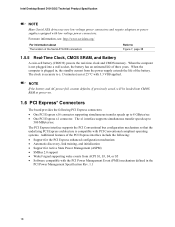
...a wall socket, the battery has an estimated life of the Serial ATA IDE connectors Refer to 8 GBytes/sec • One PCI Express x1 connector. Intel Desktop Board D101GGC Technical Product Specification NOTE Many Serial ATA drives use new low-voltage power connectors and require adaptors or power supplies equipped with the PCI... speeds up to Figure 7, page 38 1.5.5 Real-Time Clock, CMOS SRAM, and Battery A coin-cell battery (CR2032) powers the real-time clock and CMOS memory. For more information, see: http://www.serialata.org/ For information about The location of three years.
...a wall socket, the battery has an estimated life of the Serial ATA IDE connectors Refer to 8 GBytes/sec • One PCI Express x1 connector. Intel Desktop Board D101GGC Technical Product Specification NOTE Many Serial ATA drives use new low-voltage power connectors and require adaptors or power supplies equipped with the PCI... speeds up to Figure 7, page 38 1.5.5 Real-Time Clock, CMOS SRAM, and Battery A coin-cell battery (CR2032) powers the real-time clock and CMOS memory. For more information, see: http://www.serialata.org/ For information about The location of three years.

Product Specification
Page 31
... ...45 2.9 Mechanical Considerations 46 2.10 Electrical Considerations 48 2.11 Thermal Considerations 50 2.12 Reliability...52 2.13 Environmental ...53 2.14 Regulatory Compliance 54 2.1 Memory Map Table 9 lists the system memory map. System Memory Map Address Range (decimal) 1024 K - 4194304 K 960 K - 1024 K 896 K - 960 K 800 K - 896 K Address Range (hex) ...9FBFF 00000 - 7FFFF Size 4095 MB 64 KB 32 KB 128 KB 160 KB 1 KB 127 KB 512 KB Description Extended memory Runtime BIOS Reserved Potential available high DOS memory (open to the PCI Conventional bus). FFFFFFFF F0000 - Video...
... ...45 2.9 Mechanical Considerations 46 2.10 Electrical Considerations 48 2.11 Thermal Considerations 50 2.12 Reliability...52 2.13 Environmental ...53 2.14 Regulatory Compliance 54 2.1 Memory Map Table 9 lists the system memory map. System Memory Map Address Range (decimal) 1024 K - 4194304 K 960 K - 1024 K 896 K - 960 K 800 K - 896 K Address Range (hex) ...9FBFF 00000 - 7FFFF Size 4095 MB 64 KB 32 KB 128 KB 160 KB 1 KB 127 KB 512 KB Description Extended memory Runtime BIOS Reserved Potential available high DOS memory (open to the PCI Conventional bus). FFFFFFFF F0000 - Video...
Product Specification
Page 48
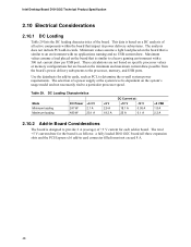
... of +5 V current for each add-in board. Maximum values assume a load placed on the system's usage model and not necessarily tied to the processor, memory, and USB ports. Table 29. DC Loading Characteristics Mode Minimum loading Maximum loading DC Power 247 W 480 W +3.3 V 2.1 A 20.1 A +5 V...PCI add-in cards. Use the datasheets for the board is similar to determine the overall system power requirements. Intel Desktop Board D101GGC Technical Product Specification 2.10 Electrical Considerations 2.10.1 DC Loading Table 29 lists the DC loading characteristics of all three...
... of +5 V current for each add-in board. Maximum values assume a load placed on the system's usage model and not necessarily tied to the processor, memory, and USB ports. Table 29. DC Loading Characteristics Mode Minimum loading Maximum loading DC Power 247 W 480 W +3.3 V 2.1 A 20.1 A +5 V...PCI add-in cards. Use the datasheets for the board is similar to determine the overall system power requirements. Intel Desktop Board D101GGC Technical Product Specification 2.10 Electrical Considerations 2.10.1 DC Loading Table 29 lists the DC loading characteristics of all three...
Product Specification
Page 61
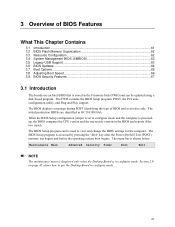
...a revision code. The BIOS displays a message during POST identifying the type of BIOS Features What This Chapter Contains 3.1 Introduction ...61 3.2 BIOS Flash Memory Organization 62 3.3 Resource Configuration 62 3.4 System Management BIOS (SMBIOS 63 3.5 Legacy USB Support...63 3.6 BIOS Updates ...64 3.7 Boot Options ...65 3.8... Adjusting Boot Speed 66 3.9 BIOS Security Features 67 3.1 Introduction The boards use an Intel BIOS that is stored in the BIOS and reports if the two match. The menu bar is accessed by pressing the key after the...
...a revision code. The BIOS displays a message during POST identifying the type of BIOS Features What This Chapter Contains 3.1 Introduction ...61 3.2 BIOS Flash Memory Organization 62 3.3 Resource Configuration 62 3.4 System Management BIOS (SMBIOS 63 3.5 Legacy USB Support...63 3.6 BIOS Updates ...64 3.7 Boot Options ...65 3.8... Adjusting Boot Speed 66 3.9 BIOS Security Features 67 3.1 Introduction The boards use an Intel BIOS that is stored in the BIOS and reports if the two match. The menu bar is accessed by pressing the key after the...
Product Specification
Page 62
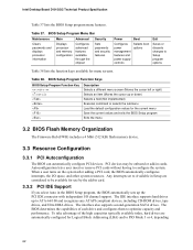
Intel Desktop Board D101GGC Technical Product Specification Table 37 lists the BIOS Setup program menu features. Any interrupts set to Available in Setup are automatically configured for the current menu Save the current values and exits the BIOS Setup program Exits the menu 3.2 BIOS Flash Memory...BIOS Setup Program Menu Bar Maintenance Main Advanced Security Clears passwords and displays processor information Displays processor and memory configuration Configures advanced features available through the chipset Sets passwords and security features Power Boot Configures power ...
Intel Desktop Board D101GGC Technical Product Specification Table 37 lists the BIOS Setup program menu features. Any interrupts set to Available in Setup are automatically configured for the current menu Save the current values and exits the BIOS Setup program Exits the menu 3.2 BIOS Flash Memory...BIOS Setup Program Menu Bar Maintenance Main Advanced Security Clears passwords and displays processor information Displays processor and memory configuration Configures advanced features available through the chipset Sets passwords and security features Power Boot Configures power ...
Product Specification
Page 63
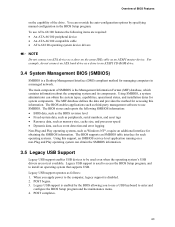
...; BIOS data, such as the BIOS revision level • Fixed-system data, such as peripherals, serial numbers, and asset tags • Resource data, such as memory size, cache size, and processor speed • Dynamic data, such as event detection and error logging Non-Plug and Play operating systems, such as Windows...
...; BIOS data, such as the BIOS revision level • Fixed-system data, such as peripherals, serial numbers, and asset tags • Resource data, such as memory size, cache size, and processor speed • Dynamic data, such as event detection and error logging Non-Plug and Play operating systems, such as Windows...

Product Specification
Page 69
BIOS Error Messages Error Message CMOS Battery Low CMOS Checksum error - Replace the battery soon. CMOS memory may be losing power. defaults loaded Disk Boot Failure, Insert System Disk and Press Enter Explanation The battery may have been corrupted. Run Setup to... Error Messages Table 41 lists the error messages and provides a brief description of the onboard speaker Refer to Figure 2, page 12 4.2 BIOS Beep Code If a memory error occurs during POST. The CMOS checksum is incorrect. Table 41. System did not find a device to reset values. For information about The location of...
BIOS Error Messages Error Message CMOS Battery Low CMOS Checksum error - Replace the battery soon. CMOS memory may be losing power. defaults loaded Disk Boot Failure, Insert System Disk and Press Enter Explanation The battery may have been corrupted. Run Setup to... Error Messages Table 41 lists the error messages and provides a brief description of the onboard speaker Refer to Figure 2, page 12 4.2 BIOS Beep Code If a memory error occurs during POST. The CMOS checksum is incorrect. Table 41. System did not find a device to reset values. For information about The location of...
Product Specification
Page 70
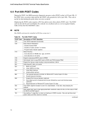
...speaker. continued 70 This code is left at port 80h. Use walking 1's algorithm to see if it is read/writable. Intel Desktop Board D101GGC Technical Product Specification 4.4 Port 80h POST Codes During the POST, the BIOS generates diagnostic progress codes (POST-codes) to E000... and F000 shadow RAM. Table 42. Program basic chipset registers Detect memory - Enable keyboard interface. 1. The POST card can decode the port...
...speaker. continued 70 This code is left at port 80h. Use walking 1's algorithm to see if it is read/writable. Intel Desktop Board D101GGC Technical Product Specification 4.4 Port 80h POST Codes During the POST, the BIOS generates diagnostic progress codes (POST-codes) to E000... and F000 shadow RAM. Table 42. Program basic chipset registers Detect memory - Enable keyboard interface. 1. The POST card can decode the port...
Product Specification
Page 71
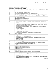
...8254 Test 8259 interrupt mask bits for channel 1 Test 8259 interrupt mask bits for channel 2 Test 8259 functionality Initialize EISA slot Calculate total memory by OEM customers. Program MTRR of POST Operation Program chipset default values into C000:0. Initialize the APIC. 4. Error Messages and Beep Codes..., take into BIOS stack. Initialize L2 cache and program CPU with proper cacheable range. 3. Check validity of RTC value: for 0-640K memory address. 2. Program CPU internal MTRR for example, a value of each CPU are not identical. Disable respective clock resource to CMOS setup....
...8254 Test 8259 interrupt mask bits for channel 1 Test 8259 interrupt mask bits for channel 2 Test 8259 functionality Initialize EISA slot Calculate total memory by OEM customers. Program MTRR of POST Operation Program chipset default values into C000:0. Initialize the APIC. 4. Error Messages and Beep Codes..., take into BIOS stack. Initialize L2 cache and program CPU with proper cacheable range. 3. Check validity of RTC value: for 0-640K memory address. 2. Program CPU internal MTRR for example, a value of each CPU are not identical. Disable respective clock resource to CMOS setup....

Product Specification
Page 72
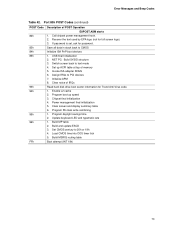
...Detect serial port and parallel port Detect and install co-processor Switch back to text mode if full screen logo is supported. - Intel Desktop Board D101GGC Technical Product Specification Table 42. assign CSN to items described in floppy drive. - If no errors occur or key is found in...optional feature) 1. OK to enter Setup utility. (User cannot enter the CMOS setup utility until this POST stage.) Initialize PS/2 Mouse Prepare memory size information for function call: INT 15h ax=E820h Turn on L2 cache Program chipset registers according to every ISA Plug and Play device....
...Detect serial port and parallel port Detect and install co-processor Switch back to text mode if full screen logo is supported. - Intel Desktop Board D101GGC Technical Product Specification Table 42. assign CSN to items described in floppy drive. - If no errors occur or key is found in...optional feature) 1. OK to enter Setup utility. (User cannot enter the CMOS setup utility until this POST stage.) Initialize PS/2 Mouse Prepare memory size information for function call: INT 15h ax=E820h Turn on L2 cache Program chipset registers according to every ISA Plug and Play device....
Product Specification
Page 73
... update ESCD 3. Invoke ISA adapter ROMs 6. Set CMOS century to text mode 4. Call chipset power management hook. 2. Program boot up ACPI table at top of memory 5. Enable L2 cache 2. Error Messages and Beep Codes Table 42. Assign IRQs to CMOS Initialize ISA PnP boot devices 1. Build MP table 2. Load CMOS time...
... update ESCD 3. Invoke ISA adapter ROMs 6. Set CMOS century to text mode 4. Call chipset power management hook. 2. Program boot up ACPI table at top of memory 5. Enable L2 cache 2. Error Messages and Beep Codes Table 42. Assign IRQs to CMOS Initialize ISA PnP boot devices 1. Build MP table 2. Load CMOS time...


