Product Guide
Page 5
Contents 1 Desktop Board Features Supported Operating Systems 10 Desktop Board Components 11 Processor ...13 Main Memory...14 Intel® X58 Express Chipset 15 Audio Subsystem 15 LAN Subsystem 16 USB 2.0 Support 17 Serial ATA...17 Legacy I/O ...18 Expandability...18 ...Auto Configuration 18 PCI and PCI Express* Auto Configuration 19 Security Passwords 19 Hardware Management 19 Hardware Monitoring and Fan Speed Control 19 Intel® Precision Cooling Technology 20 Chassis Intrusion 20 Power Management 20 Software Support 20 ACPI 20 Hardware Support 20 Power Connectors 20 Fan...
Contents 1 Desktop Board Features Supported Operating Systems 10 Desktop Board Components 11 Processor ...13 Main Memory...14 Intel® X58 Express Chipset 15 Audio Subsystem 15 LAN Subsystem 16 USB 2.0 Support 17 Serial ATA...17 Legacy I/O ...18 Expandability...18 ...Auto Configuration 18 PCI and PCI Express* Auto Configuration 19 Security Passwords 19 Hardware Management 19 Hardware Monitoring and Fan Speed Control 19 Intel® Precision Cooling Technology 20 Chassis Intrusion 20 Power Management 20 Software Support 20 ACPI 20 Hardware Support 20 Power Connectors 20 Fan...
Product Guide
Page 6
... Passwords 56 Replacing the Battery 57 3 Updating the BIOS Updating the BIOS with the Intel® Express BIOS Update Utility 63 Updating the BIOS with the ISO Image BIOS Update File or the Iflash Memory Update Utility 64 Obtaining the BIOS Update File 64 Updating the BIOS with the ISO ...Image BIOS Update File 64 Updating the BIOS with the Iflash Memory Update Utility 65 Recovering the BIOS 66 4 Configuring for RAID Configuring for RAID Using Intel® Matrix Storage Technology 67 Configuring the BIOS 67 Creating Your RAID Set 67 Loading the...
... Passwords 56 Replacing the Battery 57 3 Updating the BIOS Updating the BIOS with the Intel® Express BIOS Update Utility 63 Updating the BIOS with the ISO Image BIOS Update File or the Iflash Memory Update Utility 64 Obtaining the BIOS Update File 64 Updating the BIOS with the ISO ...Image BIOS Update File 64 Updating the BIOS with the Iflash Memory Update Utility 65 Recovering the BIOS 66 4 Configuring for RAID Configuring for RAID Using Intel® Matrix Storage Technology 67 Configuring the BIOS 67 Creating Your RAID Set 67 Loading the...

Product Guide
Page 7
.... HDD Activity LED 17 4. Remove the Protective Socket Cover 32 12. Close the Load Plate 34 15. Single Channel Memory Configuration 39 21. Installing a DIMM 40 23. Intel Desktop Board DX58SO Components 11 2. Location of the VR and CPU LEDs 25 7. Onboard Power Button 24... 6. Intel Desktop Board DX58SO Mounting Screw Hole Locations 30 9. Dual Channel Memory Configuration 38 20. Contents A Error Messages and Indicators BIOS Beep Codes 71 BIOS Error Messages 71 B Regulatory ...
.... HDD Activity LED 17 4. Remove the Protective Socket Cover 32 12. Close the Load Plate 34 15. Single Channel Memory Configuration 39 21. Installing a DIMM 40 23. Intel Desktop Board DX58SO Components 11 2. Location of the VR and CPU LEDs 25 7. Onboard Power Button 24... 6. Intel Desktop Board DX58SO Mounting Screw Hole Locations 30 9. Dual Channel Memory Configuration 38 20. Contents A Error Messages and Indicators BIOS Beep Codes 71 BIOS Error Messages 71 B Regulatory ...

Product Guide
Page 9
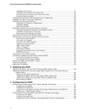
...DIMMs • Support for non-ECC memory • Support for Serial ATA continued 9 Table 1 summarizes the major features of : • Intel X58 Express Chipset I/O Controller Hub (IOH) • Intel® I/O Controller Hub (ICH10R) supporting Intel® Matrix Storage Technology Graphics Audio ... Gb/s) via ICH10R • Two external SATA (eSATA) channels via a discrete controller • Intel® Matrix Storage Technology for up to 16 GB of system memory Intel® X58 Express Chipset consisting of the Desktop Board. 1 Desktop Board Features This chapter briefly describes...
...DIMMs • Support for non-ECC memory • Support for Serial ATA continued 9 Table 1 summarizes the major features of : • Intel X58 Express Chipset I/O Controller Hub (IOH) • Intel® I/O Controller Hub (ICH10R) supporting Intel® Matrix Storage Technology Graphics Audio ... Gb/s) via ICH10R • Two external SATA (eSATA) channels via a discrete controller • Intel® Matrix Storage Technology for up to 16 GB of system memory Intel® X58 Express Chipset consisting of the Desktop Board. 1 Desktop Board Features This chapter briefly describes...
Product Guide
Page 10
... controller including an RJ-45 back panel connector with integrated status LEDs • Intel® Platform Innovation Framework for extensible firmware interface • 16 Mb symmetrical flash memory device • Support for SMBIOS • Intel® Rapid BIOS Boot • Intel® Express BIOS Update Power Management • Support for Advanced Configuration and Power...
... controller including an RJ-45 back panel connector with integrated status LEDs • Intel® Platform Innovation Framework for extensible firmware interface • 16 Mb symmetrical flash memory device • Support for SMBIOS • Intel® Rapid BIOS Boot • Intel® Express BIOS Update Power Management • Support for Advanced Configuration and Power...

Product Guide
Page 14
... 2 14 The Desktop Board supports the following links or pages for more information about: • SDRAM specifications, http://www.intel.com/technology/memory/ • Installing memory, page 38 in graphics cards. If your memory modules do not support SPD, you will attempt to this effect on the screen at power up. The operating system...
... 2 14 The Desktop Board supports the following links or pages for more information about: • SDRAM specifications, http://www.intel.com/technology/memory/ • Installing memory, page 38 in graphics cards. If your memory modules do not support SPD, you will attempt to this effect on the screen at power up. The operating system...

Product Guide
Page 21
... awake state. 21 Desktop Board Features The Desktop Board has three power connectors. See Figure 30 on the front panel, the sleep state is in memory. Fan Headers The function/operation of the power connectors. The Desktop Board has a 4-pin processor fan header, one 4-pin and two 3-pin chassis fan headers...
... awake state. 21 Desktop Board Features The Desktop Board has three power connectors. See Figure 30 on the front panel, the sleep state is in memory. Fan Headers The function/operation of the power connectors. The Desktop Board has a 4-pin processor fan header, one 4-pin and two 3-pin chassis fan headers...

Product Guide
Page 22
... appears to be used to wake the computer. +5 V Standby Power Indicator CAUTION If the AC power has been switched off . Figure 4. Intel Desktop Board DX58SO Product Guide The Desktop Board supports the PCI Bus Power Management Interface Specification. Failure to do so could damage the board and... any devices connected to the Technical Product Specification at the memory module sockets and the PCI bus connectors. Add-in power management and can be off and the standby power indicator is standby power...
... appears to be used to wake the computer. +5 V Standby Power Indicator CAUTION If the AC power has been switched off . Figure 4. Intel Desktop Board DX58SO Product Guide The Desktop Board supports the PCI Bus Power Management Interface Specification. Failure to do so could damage the board and... any devices connected to the Technical Product Specification at the memory module sockets and the PCI bus connectors. Add-in power management and can be off and the standby power indicator is standby power...

Product Guide
Page 27
... Board • Install and remove a processor • Install the ICH heat sink decorative cover • Install the IOH heat sink fan • Install and remove memory • Install and remove a PCI Express x16 card • Connect the IDE and Serial ATA cables • Connect to the internal headers and connectors •...
... Board • Install and remove a processor • Install the ICH heat sink decorative cover • Install the IOH heat sink fan • Install and remove memory • Install and remove a PCI Express x16 card • Connect the IDE and Serial ATA cables • Connect to the internal headers and connectors •...

Product Guide
Page 38
... Channel A, DIMM 1 may result in three channels (A, B, and C). Dual Channel Memory Configuration 38 Intel Desktop Board DX58SO Product Guide Installing and Removing Memory Intel Desktop board DX58SO has four 240-pin DDR3 DIMM sockets arranged in less than optimal memory performance. A typical single channel configuration is shown in Figure 18. Channel A shares two sockets (DIMM...
... Channel A, DIMM 1 may result in three channels (A, B, and C). Dual Channel Memory Configuration 38 Intel Desktop Board DX58SO Product Guide Installing and Removing Memory Intel Desktop board DX58SO has four 240-pin DDR3 DIMM sockets arranged in less than optimal memory performance. A typical single channel configuration is shown in Figure 18. Channel A shares two sockets (DIMM...

Product Guide
Page 39
Use DDR3 DIMMs 39 All the notches should match with the DDR3 DIMM. Figure 21. Single Channel Memory Configuration Installing DIMMs To make sure you have the correct DIMM, place it on the illustration of the DDR3 DIMM in Figure 21. Installing and Replacing Desktop Board Components Figure 20.
Use DDR3 DIMMs 39 All the notches should match with the DDR3 DIMM. Figure 21. Single Channel Memory Configuration Installing DIMMs To make sure you have the correct DIMM, place it on the illustration of the DDR3 DIMM in Figure 21. Installing and Replacing Desktop Board Components Figure 20.

Product Guide
Page 57
Replacing the Battery A coin-cell battery (CR2032) powers the real-time clock and CMOS memory. Replace the battery with local environmental regulations. Disposal of used batteries must be in , the standby current from the power supply extends the life of ...
Replacing the Battery A coin-cell battery (CR2032) powers the real-time clock and CMOS memory. Replace the battery with local environmental regulations. Disposal of used batteries must be in , the standby current from the power supply extends the life of ...
Product Guide
Page 63
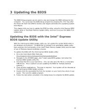
.... Double-click the executable file from the location on your hard drive. (You can access the BIOS Setup program by either using the Intel Express BIOS Update utility or the Iflash Memory Update utility, and how to recover the BIOS if an update fails. To update the BIOS with the...applications. This step is useful if you can update the system BIOS while in an automated update utility that combines the functionality of the Intel® Flash Memory Update Utility and the ease of use of Windows-based installation wizards. The BIOS file is included in the Windows environment. You can...
.... Double-click the executable file from the location on your hard drive. (You can access the BIOS Setup program by either using the Intel Express BIOS Update utility or the Iflash Memory Update utility, and how to recover the BIOS if an update fails. To update the BIOS with the...applications. This step is useful if you can update the system BIOS while in an automated update utility that combines the functionality of the Intel® Flash Memory Update Utility and the ease of use of Windows-based installation wizards. The BIOS file is included in the Windows environment. You can...
Product Guide
Page 64
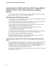
...to CD. The Iflash BIOS update file contains: • New BIOS file (including the Intel® Management Engine Firmware Image) • Intel® Integrator Toolkit Configuration File (optional) • Intel Flash Memory Update Utility You can be used to create a bootable CD that contains the files you need... Wide Web site at: http://support.intel.com/support/motherboards/desktop Navigate to remove the BIOS configuration jumper. Updating the BIOS with the ISO Image BIOS Update File or the Iflash Memory Update Utility You can use the information in this section to upgrade the ...
...to CD. The Iflash BIOS update file contains: • New BIOS file (including the Intel® Management Engine Firmware Image) • Intel® Integrator Toolkit Configuration File (optional) • Intel Flash Memory Update Utility You can be used to create a bootable CD that contains the files you need... Wide Web site at: http://support.intel.com/support/motherboards/desktop Navigate to remove the BIOS configuration jumper. Updating the BIOS with the ISO Image BIOS Update File or the Iflash Memory Update Utility You can use the information in this section to upgrade the ...
Product Guide
Page 65
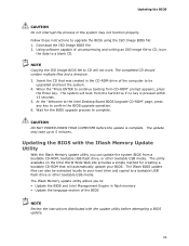
...; Update the language section of the BIOS NOTE Review the instructions distributed with the Iflash Memory Update Utility With the Iflash Memory update utility you to: • Update the BIOS and Intel Management Engine in the CD-ROM drive of uncompressing and writing an ISO image file to CD, burn the data to...
...; Update the language section of the BIOS NOTE Review the instructions distributed with the Iflash Memory Update Utility With the Iflash Memory update utility you to: • Update the BIOS and Intel Management Engine in the CD-ROM drive of uncompressing and writing an ISO image file to CD, burn the data to...

Product Guide
Page 67
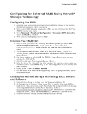
... to select RAID 0 or RAID 1 (if only two SATA drives are available), RAID 5 and RAID 10 (these options will see the following Intel Matrix Storage Manager option ROM status message on the remaining portion of your system and attach two or more than two drives available) and press... Configuration Configure SATA as; Go to Create Volume. 8. Then save your settings by pressing after the Power-On-Self-Test (POST) memory tests begin. 3. In the Intel Matrix Storage Manager option ROM Main Menu, select option #1: Create RAID Volume. Press once you will only appear if three or four ...
... to select RAID 0 or RAID 1 (if only two SATA drives are available), RAID 5 and RAID 10 (these options will see the following Intel Matrix Storage Manager option ROM status message on the remaining portion of your system and attach two or more than two drives available) and press... Configuration Configure SATA as; Go to Create Volume. 8. Then save your settings by pressing after the Power-On-Self-Test (POST) memory tests begin. 3. In the Intel Matrix Storage Manager option ROM Main Menu, select option #1: Create RAID Volume. Press once you will only appear if three or four ...
Product Guide
Page 69
...) and press . 6. Loading the Marvell Storage Technology RAID Drivers and Software 1. Begin Windows Setup by pressing the key after the Power-On-Self-Test (POST) memory tests begin. 3. Assemble your settings by pressing or going to the EXIT option in a USB floppy disk drive. In the Marvell Storage Manager option ROM...
...) and press . 6. Loading the Marvell Storage Technology RAID Drivers and Software 1. Begin Windows Setup by pressing the key after the Power-On-Self-Test (POST) memory tests begin. 3. Assemble your settings by pressing or going to the EXIT option in a USB floppy disk drive. In the Marvell Storage Manager option ROM...
Product Guide
Page 71
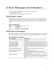
... ECC Error occurred. The firmware has detected that a Multi-Bit ECC Error occurred. Maximum memory performance is required for reliable operation. BIOS Error Messages Error Message PROCESSOR_THERMAL_TRIP_ERROR MULTI_BIT_ECC_ERROR SINGLE_BIT_ECC_ERROR CMOS_BATTERY_ERROR CMOS_CHECKSUM_ERROR... CMOS_TIMER_ERROR MEMORY_SIZE_DECREASE_ERROR INTRUDER_DETECTION_ERROR SPD_TOLER_ERROR MEM_OPTIMAL_ERROR Explanation Processor was opened. A Error Messages and Indicators Intel Desktop Board DX58SO reports POST errors in two ways: • By sounding a beep code ...
... ECC Error occurred. The firmware has detected that a Multi-Bit ECC Error occurred. Maximum memory performance is required for reliable operation. BIOS Error Messages Error Message PROCESSOR_THERMAL_TRIP_ERROR MULTI_BIT_ECC_ERROR SINGLE_BIT_ECC_ERROR CMOS_BATTERY_ERROR CMOS_CHECKSUM_ERROR... CMOS_TIMER_ERROR MEMORY_SIZE_DECREASE_ERROR INTRUDER_DETECTION_ERROR SPD_TOLER_ERROR MEM_OPTIMAL_ERROR Explanation Processor was opened. A Error Messages and Indicators Intel Desktop Board DX58SO reports POST errors in two ways: • By sounding a beep code ...


