
Product Guide
Page 5
Contents 1 Desktop Board Features Desktop Board Components 10 Processor ...12 Main Memory...12 Intel® 945GC Express Chipset 13 S-Video Support 13 Onboard Audio Subsystem 13 Input/Output (I/O) Controller 14 LAN Subsystem 15 LAN Subsystem Software 15...Begin 21 Installation Precautions 22 Prevent Power Supply Overload 22 Observe Safety and Regulatory Requirements 22 Installing the I/O Shield 23 Installing and Removing the Desktop Board 24 Installing and Removing Memory 25 Installing DIMMs 25 Removing DIMMs 27 Connecting the IDE Cable 27 Connecting the Serial ATA (SATA) Cable ...
Contents 1 Desktop Board Features Desktop Board Components 10 Processor ...12 Main Memory...12 Intel® 945GC Express Chipset 13 S-Video Support 13 Onboard Audio Subsystem 13 Input/Output (I/O) Controller 14 LAN Subsystem 15 LAN Subsystem Software 15...Begin 21 Installation Precautions 22 Prevent Power Supply Overload 22 Observe Safety and Regulatory Requirements 22 Installing the I/O Shield 23 Installing and Removing the Desktop Board 24 Installing and Removing Memory 25 Installing DIMMs 25 Removing DIMMs 27 Connecting the IDE Cable 27 Connecting the Serial ATA (SATA) Cable ...
Product Guide
Page 9
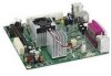
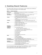
...1 Desktop Board Features This chapter briefly describes the main features of : • Intel® 82945GC Express Chipset Graphics and Memory Controller Hub (GMCH) • Intel® 82801GB I/O Controller Hub (ICH7) • Integrated graphics via the Intel® Graphics Media Accelerator 950 (Intel®... For more information about Intel Desktop Board D945GCLF2, including the Technical Product Specification (TPS), BIOS updates, and device drivers, go to http://support.intel.com/support/motherboards/desktop/. 9 Table 1. Feature Summary Form Factor Processor Main Memory Chipset Graphics ...
...1 Desktop Board Features This chapter briefly describes the main features of : • Intel® 82945GC Express Chipset Graphics and Memory Controller Hub (GMCH) • Intel® 82801GB I/O Controller Hub (ICH7) • Integrated graphics via the Intel® Graphics Media Accelerator 950 (Intel®... For more information about Intel Desktop Board D945GCLF2, including the Technical Product Specification (TPS), BIOS updates, and device drivers, go to http://support.intel.com/support/motherboards/desktop/. 9 Table 1. Feature Summary Form Factor Processor Main Memory Chipset Graphics ...
Product Guide
Page 12
...-ECC memory • Up to 2 GB of memory For the latest list of tested memory, go to the Desktop Board and is soldered to http://support.intel.com/support/motherboards/desktop/. 12 Intel Desktop Board D945GCLF2 includes a Dual-Core Intel Atom processor. The Desktop Board has one 240-pin Double Data Rate 2 (DDR2) SDRAM Dual Inline Memory Module (DIMM) connector with DIMMs that...
...-ECC memory • Up to 2 GB of memory For the latest list of tested memory, go to the Desktop Board and is soldered to http://support.intel.com/support/motherboards/desktop/. 12 Intel Desktop Board D945GCLF2 includes a Dual-Core Intel Atom processor. The Desktop Board has one 240-pin Double Data Rate 2 (DDR2) SDRAM Dual Inline Memory Module (DIMM) connector with DIMMs that...

Product Guide
Page 13
...― Line in/retasking jack ― Line out/retasking jack ― Mic in/retasking jack 13 Desktop Board Features Intel® 945GC Express Chipset The Intel 945GC Express Chipset consists of the following headers and connectors: • Onboard S/PDIF connector (3-pin) &#... centralized controller for the board's I /O Controller Hub (ICH7) The GMCH component provides interfaces to the processor, memory, and the DMI interconnect. This component also provides integrated graphics capabilities via the audio driver. • S/N (signal-to http://www.intel.com/design/chipsets/express_flyer....
...― Line in/retasking jack ― Line out/retasking jack ― Mic in/retasking jack 13 Desktop Board Features Intel® 945GC Express Chipset The Intel 945GC Express Chipset consists of the following headers and connectors: • Onboard S/PDIF connector (3-pin) &#... centralized controller for the board's I /O Controller Hub (ICH7) The GMCH component provides interfaces to the processor, memory, and the DMI interconnect. This component also provides integrated graphics capabilities via the audio driver. • S/N (signal-to http://www.intel.com/design/chipsets/express_flyer....
Product Guide
Page 16
... computer. The interface supports: • Up to USB 1.1 operation. This may be required to two onboard USB 2.0 headers). The Desktop Board supports up to eight USB 2.0 ports (four ports routed to the back panel and four ports routed to accommodate operating systems that have...of information between the processor and peripheral devices such as CD-ROM or DVD drives) • Older PIO Mode devices • Ultra DMA-33/66/100 modes Serial ATA The Desktop Board supports two Serial ATA channels (3.0 Gb/s), connecting one device per channel. Intel Desktop Board D945GCLF2 Product Guide Hi...
... computer. The interface supports: • Up to USB 1.1 operation. This may be required to two onboard USB 2.0 headers). The Desktop Board supports up to eight USB 2.0 ports (four ports routed to the back panel and four ports routed to accommodate operating systems that have...of information between the processor and peripheral devices such as CD-ROM or DVD drives) • Older PIO Mode devices • Ultra DMA-33/66/100 modes Serial ATA The Desktop Board supports two Serial ATA channels (3.0 Gb/s), connecting one device per channel. Intel Desktop Board D945GCLF2 Product Guide Hi...

Product Guide
Page 34
... the system may not function properly. Connecting a 2 x 10 or 2 x 12 Power Supply Cable 1. Connect the 12 V processor core voltage power supply cable to the 2 x 12 connector (Figure 13). 34 Intel Desktop Board D945GCLF2 Product Guide Connecting Power Supply Cables CAUTION Failure to use an appropriate power supply and/or not connecting the 12 V (2 x 2) power...
... the system may not function properly. Connecting a 2 x 10 or 2 x 12 Power Supply Cable 1. Connect the 12 V processor core voltage power supply cable to the 2 x 12 connector (Figure 13). 34 Intel Desktop Board D945GCLF2 Product Guide Connecting Power Supply Cables CAUTION Failure to use an appropriate power supply and/or not connecting the 12 V (2 x 2) power...

Product Guide
Page 45
... off for 0.5 second Off when update begins, then on -off blink pattern; These beep codes can be heard through a speaker attached to the board's line out jack (see Table 9). repeat entire pattern (four on-off blinks and 3-second pause) until system is powered off Memory error On-off... (0.5 second each) three times, then 3.0 second pause (off) between on , and blinks off for 0.5 second when processor initialization is powered off Thermal warning On-off (0.5 second each ) two times, then 3.0 second pause (off) between on page 14). Table 10. BIOS ...
... off for 0.5 second Off when update begins, then on -off blink pattern; These beep codes can be heard through a speaker attached to the board's line out jack (see Table 9). repeat entire pattern (four on-off blinks and 3-second pause) until system is powered off Memory error On-off... (0.5 second each) three times, then 3.0 second pause (off) between on , and blinks off for 0.5 second when processor initialization is powered off Thermal warning On-off (0.5 second each ) two times, then 3.0 second pause (off) between on page 14). Table 10. BIOS ...


