
Product Guide
Page 5
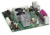
Contents 1 Desktop Board Features Desktop Board Components 10 Processor ...12 Main Memory...12 Intel® 945GC Express Chipset 13 S-Video Support 13 Onboard Audio Subsystem 13 Input/Output (I/O) Controller 14 LAN Subsystem 15 LAN Subsystem Software 15 LAN......18 Hardware Support 18 Power Connectors 18 Fan Headers 18 +5 V Standby Power Indicator LED 18 LAN Wake Capabilities 19 Wake from USB 19 Wake from PS/2 Keyboard/Mouse 20 PME# Wakeup Support 20 Battery ...20 Real-Time Clock 20 2 Installing and Replacing Desktop Board Components Before You Begin 21 Installation Precautions ...
Contents 1 Desktop Board Features Desktop Board Components 10 Processor ...12 Main Memory...12 Intel® 945GC Express Chipset 13 S-Video Support 13 Onboard Audio Subsystem 13 Input/Output (I/O) Controller 14 LAN Subsystem 15 LAN Subsystem Software 15 LAN......18 Hardware Support 18 Power Connectors 18 Fan Headers 18 +5 V Standby Power Indicator LED 18 LAN Wake Capabilities 19 Wake from USB 19 Wake from PS/2 Keyboard/Mouse 20 PME# Wakeup Support 20 Battery ...20 Real-Time Clock 20 2 Installing and Replacing Desktop Board Components Before You Begin 21 Installation Precautions ...
Product Guide
Page 6
Intel Desktop Board D945GCLF2 Product Guide Connecting to the Front Panel Header 32 Connecting the Hi-Speed USB 2.0 Headers 32 Connecting a Chassis Fan 33 Connecting Power Supply Cables 34 Setting the BIOS Configuration Jumper 35 Clearing Passwords 36 Replacing the Battery 37 3 Updating the BIOS Updating the BIOS with the Intel...Union Declaration of Conformity Statement 48 Product Ecology Statements 49 Recycling Considerations 49 Lead-free 2LI/Pb-free 2LI Board 52 Restriction of Hazardous Substances (RoHS 53 European Union RoHS 53 China RoHS 53 EMC Regulations 55 Ensure ...
Intel Desktop Board D945GCLF2 Product Guide Connecting to the Front Panel Header 32 Connecting the Hi-Speed USB 2.0 Headers 32 Connecting a Chassis Fan 33 Connecting Power Supply Cables 34 Setting the BIOS Configuration Jumper 35 Clearing Passwords 36 Replacing the Battery 37 3 Updating the BIOS Updating the BIOS with the Intel...Union Declaration of Conformity Statement 48 Product Ecology Statements 49 Recycling Considerations 49 Lead-free 2LI/Pb-free 2LI Board 52 Restriction of Hazardous Substances (RoHS 53 European Union RoHS 53 China RoHS 53 EMC Regulations 55 Ensure ...
Product Guide
Page 7
...Codes 45 10. Location of the Chassis Fan Header 33 13. Connecting the Serial ATA Cable 29 11. Connecting a 2 x 10 or 2 x 12 Power Supply Cable 34 14. S/PDIF Connector Signal Names 31 6. Safety Standards 47 13. Intel Desktop Board D945GCLF2 Mounting Screw Holes 24 7. Connecting ...1. Front Panel Audio Header Signal Names for the BIOS Setup Program Modes 36 9. Hi-Speed USB 2.0 Headers Signal Names 32 8. Intel Desktop Board D945GCLF2 Components 10 2. BIOS Configuration Jumper Block 35 15. BIOS Beep Codes 45 11. EMC Regulations 55 16. China RoHS Environmentally ...
...Codes 45 10. Location of the Chassis Fan Header 33 13. Connecting the Serial ATA Cable 29 11. Connecting a 2 x 10 or 2 x 12 Power Supply Cable 34 14. S/PDIF Connector Signal Names 31 6. Safety Standards 47 13. Intel Desktop Board D945GCLF2 Mounting Screw Holes 24 7. Connecting ...1. Front Panel Audio Header Signal Names for the BIOS Setup Program Modes 36 9. Hi-Speed USB 2.0 Headers Signal Names 32 8. Intel Desktop Board D945GCLF2 Components 10 2. BIOS Configuration Jumper Block 35 15. BIOS Beep Codes 45 11. EMC Regulations 55 16. China RoHS Environmentally ...
Product Guide
Page 18
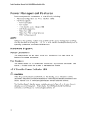
... Support Power Connectors The Desktop Board has two power connectors. Fan Headers The Desktop Board has a 3-pin MCH fan header and a 3-pin chassis fan header. This includes the DIMM socket and the PCI bus connector, even though the computer appears to the system. See Figure 13 on page 33 for the location of a computer. Intel Desktop Board D945GCLF2 Product Guide...
... Support Power Connectors The Desktop Board has two power connectors. Fan Headers The Desktop Board has a 3-pin MCH fan header and a 3-pin chassis fan header. This includes the DIMM socket and the PCI bus connector, even though the computer appears to the system. See Figure 13 on page 33 for the location of a computer. Intel Desktop Board D945GCLF2 Product Guide...

Product Guide
Page 21
...• Install the I/O shield • Install and remove the Desktop Board • Install and remove memory • Connect the IDE cable • Connect the SATA cable • Connect internal headers • Connect chassis fan and power supply cables • Set the BIOS configuration and audio... using and modifying electronic equipment. Follow these guidelines before performing any telecommunications links, networks, or modems before you begin installing the Desktop Board: • Always follow the steps in each procedure in the correct order. • Set up a log to record information...
...• Install the I/O shield • Install and remove the Desktop Board • Install and remove memory • Connect the IDE cable • Connect the SATA cable • Connect internal headers • Connect chassis fan and power supply cables • Set the BIOS configuration and audio... using and modifying electronic equipment. Follow these guidelines before performing any telecommunications links, networks, or modems before you begin installing the Desktop Board: • Always follow the steps in each procedure in the correct order. • Set up a log to record information...

Product Guide
Page 33
Installing and Replacing Desktop Board Components Connecting a Chassis Fan Figure 12 shows the location of the Chassis Fan Header 33 Location of the chassis fan header. Figure 12. Connect the chassis fan cable to this header.
Installing and Replacing Desktop Board Components Connecting a Chassis Fan Figure 12 shows the location of the Chassis Fan Header 33 Location of the chassis fan header. Figure 12. Connect the chassis fan cable to this header.


