
Product Guide
Page 5
Contents 1 Desktop Board Features Desktop Board Components 10 Processor ...12 Main Memory...12 Intel® 945GC Express Chipset 13 S-Video Support 13 Onboard Audio Subsystem 13 Input/Output (I/O) Controller 14 LAN Subsystem 15 ... Battery ...20 Real-Time Clock 20 2 Installing and Replacing Desktop Board Components Before You Begin 21 Installation Precautions 22 Prevent Power Supply Overload 22 Observe Safety and Regulatory Requirements 22 Installing the I/O Shield 23 Installing and Removing the Desktop Board 24 Installing and Removing Memory 25 Installing DIMMs 25 Removing DIMMs...
Contents 1 Desktop Board Features Desktop Board Components 10 Processor ...12 Main Memory...12 Intel® 945GC Express Chipset 13 S-Video Support 13 Onboard Audio Subsystem 13 Input/Output (I/O) Controller 14 LAN Subsystem 15 ... Battery ...20 Real-Time Clock 20 2 Installing and Replacing Desktop Board Components Before You Begin 21 Installation Precautions 22 Prevent Power Supply Overload 22 Observe Safety and Regulatory Requirements 22 Installing the I/O Shield 23 Installing and Removing the Desktop Board 24 Installing and Removing Memory 25 Installing DIMMs 25 Removing DIMMs...
Product Guide
Page 6
Intel Desktop Board D945GCLF2 Product Guide Connecting to the Front Panel Header 32 Connecting the Hi-Speed USB 2.0 Headers 32 Connecting a Chassis Fan 33 Connecting Power Supply Cables 34 Setting the BIOS Configuration Jumper 35 Clearing Passwords 36 Replacing the Battery 37 3 Updating the BIOS Updating the BIOS with the Intel® Express BIOS Update Utility 43...
Intel Desktop Board D945GCLF2 Product Guide Connecting to the Front Panel Header 32 Connecting the Hi-Speed USB 2.0 Headers 32 Connecting a Chassis Fan 33 Connecting Power Supply Cables 34 Setting the BIOS Configuration Jumper 35 Clearing Passwords 36 Replacing the Battery 37 3 Updating the BIOS Updating the BIOS with the Intel® Express BIOS Update Utility 43...
Product Guide
Page 7
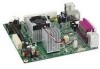
Intel Desktop Board D945GCLF2 Components 10 2. Intel Desktop Board D945GCLF2 Mounting Screw Holes 24 7. Location of the Standby Power Indicator 19 5. Intel Desktop Board D945GCLF2 Components 11 3. Front Panel Audio Header Signal Names for the BIOS Setup Program Modes ...Intel Desktop Board D945GCLF2 China RoHS Material Self Declaration Table.........54 Tables 1. BIOS Beep Codes 45 11. Installing a DIMM 26 9. Lead-Free Second Level Interconnect Marks 52 14. Back Panel Audio Connectors 14 3. Front Panel Header Signal Names 32 7. Connecting a 2 x 10 or 2 x 12 Power Supply...
Intel Desktop Board D945GCLF2 Components 10 2. Intel Desktop Board D945GCLF2 Mounting Screw Holes 24 7. Location of the Standby Power Indicator 19 5. Intel Desktop Board D945GCLF2 Components 11 3. Front Panel Audio Header Signal Names for the BIOS Setup Program Modes ...Intel Desktop Board D945GCLF2 China RoHS Material Self Declaration Table.........54 Tables 1. BIOS Beep Codes 45 11. Installing a DIMM 26 9. Lead-Free Second Level Interconnect Marks 52 14. Back Panel Audio Connectors 14 3. Front Panel Header Signal Names 32 7. Connecting a 2 x 10 or 2 x 12 Power Supply...
Product Guide
Page 12
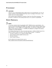
... fully compliant with all applicable Intel® SDRAM memory specifications, the board should be populated with gold-plated contacts. Intel Desktop Board D945GCLF2 includes a Dual-Core Intel Atom processor. Intel Desktop Board D945GCLF2 Product Guide Processor CAUTION Failure to use an appropriate power supply and/or not connecting the 12 V (2 x 2) power connector to the Desktop Board may result in damage to the board, or the system may not...
... fully compliant with all applicable Intel® SDRAM memory specifications, the board should be populated with gold-plated contacts. Intel Desktop Board D945GCLF2 includes a Dual-Core Intel Atom processor. Intel Desktop Board D945GCLF2 Product Guide Processor CAUTION Failure to use an appropriate power supply and/or not connecting the 12 V (2 x 2) power connector to the Desktop Board may result in damage to the board, or the system may not...

Product Guide
Page 19
.... 19 Location of the Standby Power Indicator For more information on the Intel Desktop D945GCLF2 web page at http://support.intel.com/support/motherboards/desktop/ LAN Wake Capabilities CAUTION For LAN wake capabilities, the 5 V standby line for the Desktop Board, refer to provide adequate standby current when using this feature can damage the power supply. Failure to the Technical Product...
.... 19 Location of the Standby Power Indicator For more information on the Intel Desktop D945GCLF2 web page at http://support.intel.com/support/motherboards/desktop/ LAN Wake Capabilities CAUTION For LAN wake capabilities, the 5 V standby line for the Desktop Board, refer to provide adequate standby current when using this feature can damage the power supply. Failure to the Technical Product...

Product Guide
Page 21
...correct order. • Set up a log to disconnect power, telecommunications links, networks, or modems before you open the computer or perform any telecommunications links, networks, or modems before you begin installing the Desktop Board: • Always follow the steps in each procedure in...; Install the I/O shield • Install and remove the Desktop Board • Install and remove memory • Connect the IDE cable • Connect the SATA cable • Connect internal headers • Connect chassis fan and power supply cables • Set the BIOS configuration and audio jumpers &#...
...correct order. • Set up a log to disconnect power, telecommunications links, networks, or modems before you open the computer or perform any telecommunications links, networks, or modems before you begin installing the Desktop Board: • Always follow the steps in each procedure in...; Install the I/O shield • Install and remove the Desktop Board • Install and remove memory • Connect the IDE cable • Connect the SATA cable • Connect internal headers • Connect chassis fan and power supply cables • Set the BIOS configuration and audio jumpers &#...

Product Guide
Page 22
...; Hot components (such as voltage regulators and heat sinks) • Damage to Appendix B for safety and regulatory requirements. 22 Intel Desktop Board D945GCLF2 Product Guide Installation Precautions When you install and test the Intel Desktop Board, observe all the modules within the computer is less than the output current rating of each of the power supplies output circuits.
...; Hot components (such as voltage regulators and heat sinks) • Damage to Appendix B for safety and regulatory requirements. 22 Intel Desktop Board D945GCLF2 Product Guide Installation Precautions When you install and test the Intel Desktop Board, observe all the modules within the computer is less than the output current rating of each of the power supplies output circuits.

Product Guide
Page 34
... not function properly. Connect the 12 V processor core voltage power supply cable to the 2 x 12 connector (Figure 13). 34 Figure 13 shows the location of the power connectors. Intel Desktop Board D945GCLF2 Product Guide Connecting Power Supply Cables CAUTION Failure to use an appropriate power supply and/or not connecting the 12 V (2 x 2) power connector to the Desktop Board may result in "Before You Begin...
... not function properly. Connect the 12 V processor core voltage power supply cable to the 2 x 12 connector (Figure 13). 34 Figure 13 shows the location of the power connectors. Intel Desktop Board D945GCLF2 Product Guide Connecting Power Supply Cables CAUTION Failure to use an appropriate power supply and/or not connecting the 12 V (2 x 2) power connector to the Desktop Board may result in "Before You Begin...

Product Guide
Page 37
...page 41 shows the location of used batteries must be in accordance with an equivalent one. Replacing the Battery A coin-cell battery (CR2032) powers the real-time clock and CMOS memory. When the computer is plugged in CMOS RAM (for example, the date and time) might not ... VIKTIGT! OBS! Installing and Replacing Desktop Board Components 11. Remove the computer cover. 12. Replace the cover, plug in the computer, and turn on pins 1-2 as shown below a certain level, the BIOS Setup program settings stored in , the standby current from the power supply extends the life of explosion if ...
...page 41 shows the location of used batteries must be in accordance with an equivalent one. Replacing the Battery A coin-cell battery (CR2032) powers the real-time clock and CMOS memory. When the computer is plugged in CMOS RAM (for example, the date and time) might not ... VIKTIGT! OBS! Installing and Replacing Desktop Board Components 11. Remove the computer cover. 12. Replace the cover, plug in the computer, and turn on pins 1-2 as shown below a certain level, the BIOS Setup program settings stored in , the standby current from the power supply extends the life of explosion if ...

Product Guide
Page 56
..., as applicable, have passed Class B EMC testing and are marked accordingly. Ensure Electromagnetic Compatibility (EMC) Compliance Before computer integration, make sure that is household equipment that the power supply and other non-residential environments. Intel Desktop Board D945GCLF2 Product Guide Korean Class B statement translation: This is certified to the following when reading the installation instructions for...
..., as applicable, have passed Class B EMC testing and are marked accordingly. Ensure Electromagnetic Compatibility (EMC) Compliance Before computer integration, make sure that is household equipment that the power supply and other non-residential environments. Intel Desktop Board D945GCLF2 Product Guide Korean Class B statement translation: This is certified to the following when reading the installation instructions for...

Product Guide
Page 58
Intel Desktop Board D945GCLF2 Product Guide Chassis and Component Certifications Ensure that the chassis and certain components; are components certified for the intended use signifies compliance with electromagnetic ... are proof of certification. The Industry Canada statement at the front of Conformity statement to the European EMC directive and Low Voltage directive (as the power supply, peripheral drives, wiring, and cables; In the United States A certification mark by a Nationally Recognized Testing Laboratory (NRTL) such as CSA or cUL signifies compliance with...
Intel Desktop Board D945GCLF2 Product Guide Chassis and Component Certifications Ensure that the chassis and certain components; are components certified for the intended use signifies compliance with electromagnetic ... are proof of certification. The Industry Canada statement at the front of Conformity statement to the European EMC directive and Low Voltage directive (as the power supply, peripheral drives, wiring, and cables; In the United States A certification mark by a Nationally Recognized Testing Laboratory (NRTL) such as CSA or cUL signifies compliance with...


