
Product Guide
Page 5
Contents 1 Desktop Board Features Desktop Board Components 10 Processor ...12 Main Memory...12 Intel® 945GC Express Chipset 13 Onboard Audio Subsystem 13 Input/Output (I/O) Controller 14 LAN Subsystem 15 LAN Subsystem Software 15 LAN Status ...# Wakeup Support 20 Battery ...20 Real-Time Clock 20 2 Installing and Replacing Desktop Board Components Before You Begin 21 Installation Precautions 22 Prevent Power Supply Overload 22 Observe Safety and Regulatory Requirements 22 Installing the I/O Shield 23 Installing and Removing the Desktop Board 24 Installing and Removing Memory ...
Contents 1 Desktop Board Features Desktop Board Components 10 Processor ...12 Main Memory...12 Intel® 945GC Express Chipset 13 Onboard Audio Subsystem 13 Input/Output (I/O) Controller 14 LAN Subsystem 15 LAN Subsystem Software 15 LAN Status ...# Wakeup Support 20 Battery ...20 Real-Time Clock 20 2 Installing and Replacing Desktop Board Components Before You Begin 21 Installation Precautions 22 Prevent Power Supply Overload 22 Observe Safety and Regulatory Requirements 22 Installing the I/O Shield 23 Installing and Removing the Desktop Board 24 Installing and Removing Memory ...
Product Guide
Page 6
... DG945GCLF Product Guide Connecting Power Supply Cables 33 Setting the BIOS Configuration Jumper 34 Clearing Passwords 35 Replacing the Battery 36 3 Updating the BIOS Updating the BIOS with the Intel® Express BIOS Update Utility 41 Updating the BIOS with the Iflash Memory Update Utility 41 Obtaining the BIOS Update File 41...
... DG945GCLF Product Guide Connecting Power Supply Cables 33 Setting the BIOS Configuration Jumper 34 Clearing Passwords 35 Replacing the Battery 36 3 Updating the BIOS Updating the BIOS with the Intel® Express BIOS Update Utility 41 Updating the BIOS with the Iflash Memory Update Utility 41 Obtaining the BIOS Update File 41...

Product Guide
Page 7
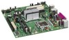
...I/O Shield 23 6. Connecting the IDE Cable 28 10. Connecting the Serial ATA Cable 29 11. Connecting a 2 x 10 or 2 x 12 Power Supply Cable 33 14. Feature Summary 9 2. Front Panel Audio Header Signal Names for the BIOS Setup Program Modes 35 8. EMC Regulations 53 15....44 11. Back Panel Audio Connectors 14 3. Removing the Battery 40 16. Desktop Boards DG945GCLF Components 11 3. Intel Desktop Board DG945GCLF Components 10 2. Jumper Settings for Intel High Definition Audio 31 5. Contents Figures 1. Use DDR2 DIMMs 25 8. BIOS Configuration Jumper Block 34 15....
...I/O Shield 23 6. Connecting the IDE Cable 28 10. Connecting the Serial ATA Cable 29 11. Connecting a 2 x 10 or 2 x 12 Power Supply Cable 33 14. Feature Summary 9 2. Front Panel Audio Header Signal Names for the BIOS Setup Program Modes 35 8. EMC Regulations 53 15....44 11. Back Panel Audio Connectors 14 3. Removing the Battery 40 16. Desktop Boards DG945GCLF Components 11 3. Intel Desktop Board DG945GCLF Components 10 2. Jumper Settings for Intel High Definition Audio 31 5. Contents Figures 1. Use DDR2 DIMMs 25 8. BIOS Configuration Jumper Block 34 15....
Product Guide
Page 9
... Processor Main Memory Chipset Graphics Audio Expansion Capabilities Peripheral Interfaces BIOS LAN Support Power Management Supported Operating Systems Mini-ITX (171.45 millimeters [6.75 inches] x 171.45 millimeters [6.75 inches]) Intel® Atom™ processor 230 • One 240-pin SDRAM Dual ...8226; PS/2* keyboard and mouse ports • Intel® BIOS • Support for SMBIOS • Intel® Rapid BIOS Boot • Intel® Express BIOS Update • 10/100 Mb/s LAN Subsystem • Support for Advanced Configuration and Power Interface (ACPI) • Wake on USB, PCI...
... Processor Main Memory Chipset Graphics Audio Expansion Capabilities Peripheral Interfaces BIOS LAN Support Power Management Supported Operating Systems Mini-ITX (171.45 millimeters [6.75 inches] x 171.45 millimeters [6.75 inches]) Intel® Atom™ processor 230 • One 240-pin SDRAM Dual ...8226; PS/2* keyboard and mouse ports • Intel® BIOS • Support for SMBIOS • Intel® Rapid BIOS Boot • Intel® Express BIOS Update • 10/100 Mb/s LAN Subsystem • Support for Advanced Configuration and Power Interface (ACPI) • Wake on USB, PCI...

Product Guide
Page 12
Intel Desktop Board DG945GCLF Product Guide Processor CAUTION Failure to use an appropriate power supply and/or not connecting the 12 V (2 x 2) power connector to the Desktop Board may not function properly. The Desktop Board has one 240-pin Double Data Rate 2 (DDR2) SDRAM Dual...the board should be populated with gold-plated contacts. The BIOS will see a notification to this effect on the screen at power up. The processor is soldered to http://support.intel.com/support/motherboards/desktop/. 12 It supports: • 667/533 MHz unbuffered, non-registered DDR2 DIMMs • Serial ...
Intel Desktop Board DG945GCLF Product Guide Processor CAUTION Failure to use an appropriate power supply and/or not connecting the 12 V (2 x 2) power connector to the Desktop Board may not function properly. The Desktop Board has one 240-pin Double Data Rate 2 (DDR2) SDRAM Dual...the board should be populated with gold-plated contacts. The BIOS will see a notification to this effect on the screen at power up. The processor is soldered to http://support.intel.com/support/motherboards/desktop/. 12 It supports: • 667/533 MHz unbuffered, non-registered DDR2 DIMMs • Serial ...

Product Guide
Page 14
... audio line out connector is designed to the following locations for more information about: • Audio drivers and utilities http://support.intel.com/support/motherboards/desktop/ • Installing a front panel audio solution (page 31) Input/Output (I/O) Controller The super I/O ...; PS/2-style mouse and keyboard interfaces • Intelligent power management, including a programmable wake up event interface • PCI power management support 14 Related Links: Go to power headphones or amplified speakers only. Intel Desktop Board DG945GCLF Product Guide Figure 2 shows the default...
... audio line out connector is designed to the following locations for more information about: • Audio drivers and utilities http://support.intel.com/support/motherboards/desktop/ • Installing a front panel audio solution (page 31) Input/Output (I/O) Controller The super I/O ...; PS/2-style mouse and keyboard interfaces • Intelligent power management, including a programmable wake up event interface • PCI power management support 14 Related Links: Go to power headphones or amplified speakers only. Intel Desktop Board DG945GCLF Product Guide Figure 2 shows the default...

Product Guide
Page 15
... drivers, refer to the DG945GCLF link on the back panel (see Figure 3). Table 3. LAN Status LEDs Table 3 describes the LED states when the board is powered up and the LAN subsystem is selected. 15 LAN Status LEDs Two LEDs are built into the RJ-45 LAN connector located on... Intel's World Wide Web site at http://support.intel.com/support/motherboards/desktop. These LEDs indicate the operating states of the LAN. LAN Status LEDs LED Activity (A) Speed (B) LED Color...
... drivers, refer to the DG945GCLF link on the back panel (see Figure 3). Table 3. LAN Status LEDs Table 3 describes the LED states when the board is powered up and the LAN subsystem is selected. 15 LAN Status LEDs Two LEDs are built into the RJ-45 LAN connector located on... Intel's World Wide Web site at http://support.intel.com/support/motherboards/desktop. These LEDs indicate the operating states of the LAN. LAN Status LEDs LED Activity (A) Speed (B) LED Color...

Product Guide
Page 17
... password is booted. A supervisor password and a user password can be accessed and who can boot the computer. Desktop Board Features BIOS The BIOS provides the Power-On Self-Test (POST), the BIOS Setup program, the PCI and IDE auto-configuration utilities, and the video BIOS. For instructions on resetting the password...
... password is booted. A supervisor password and a user password can be accessed and who can boot the computer. Desktop Board Features BIOS The BIOS provides the Power-On Self-Test (POST), the BIOS Setup program, the PCI and IDE auto-configuration utilities, and the video BIOS. For instructions on resetting the password...

Product Guide
Page 18
Intel Desktop Board DG945GCLF Product Guide Power Management Features Power management is implemented at several levels, including: • Advanced Configuration and Power Interface (ACPI) • Hardware support: ― Power connectors ― Fan headers ― +5 V standby power indicator LED ― LAN Wake capabilities ― Wake from ...from PS/2 keyboard/mouse ― PME# wakeup support ACPI ACPI gives the operating system direct control over the power management and Plug and Play functions of ACPI with the Desktop Board requires an operating system that provides full ACPI ...
Intel Desktop Board DG945GCLF Product Guide Power Management Features Power management is implemented at several levels, including: • Advanced Configuration and Power Interface (ACPI) • Hardware support: ― Power connectors ― Fan headers ― +5 V standby power indicator LED ― LAN Wake capabilities ― Wake from ...from PS/2 keyboard/mouse ― PME# wakeup support ACPI ACPI gives the operating system direct control over the power management and Plug and Play functions of ACPI with the Desktop Board requires an operating system that provides full ACPI ...

Product Guide
Page 19
Failure to the Technical Product Specification on the D945GCLF web page at: http://support.intel.com/support/motherboards/desktop/ 19 Figure 4. Location of the Standby Power Indicator For more information on standby current requirements for the Desktop Board, refer to do so could damage the... to the system. Desktop Board Features +5 V Standby Power Indicator LED CAUTION If the AC power has been switched off . The Desktop Board's standby power indicator, shown in Figure 4, is lit when there is still lit, disconnect the power cord before installing or removing any attached devices. This...
Failure to the Technical Product Specification on the D945GCLF web page at: http://support.intel.com/support/motherboards/desktop/ 19 Figure 4. Location of the Standby Power Indicator For more information on standby current requirements for the Desktop Board, refer to do so could damage the... to the system. Desktop Board Features +5 V Standby Power Indicator LED CAUTION If the AC power has been switched off . The Desktop Board's standby power indicator, shown in Figure 4, is lit when there is still lit, disconnect the power cord before installing or removing any attached devices. This...

Product Guide
Page 20
... the computer is turned off . The battery on the Desktop Board keeps the clock current when the computer is turned off . 20 Intel Desktop Board DG945GCLF Product Guide LAN Wake Capabilities CAUTION For LAN wake capabilities, the 5 V standby line for instructions on how to provide... adequate standby current when using this feature can damage the power supply. The LAN subsystem monitors network traffic and upon detecting a Magic Packet* frame, it asserts a wake-up of delivering adequate +5 V standby...
... the computer is turned off . The battery on the Desktop Board keeps the clock current when the computer is turned off . 20 Intel Desktop Board DG945GCLF Product Guide LAN Wake Capabilities CAUTION For LAN wake capabilities, the 5 V standby line for instructions on how to provide... adequate standby current when using this feature can damage the power supply. The LAN subsystem monitors network traffic and upon detecting a Magic Packet* frame, it asserts a wake-up of delivering adequate +5 V standby...
Product Guide
Page 21
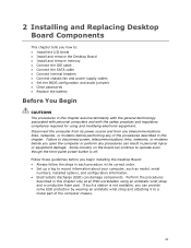
... practices and regulatory compliance required for using an antistatic wrist strap and a conductive foam pad. Disconnect the computer from its power source and from any telecommunications links, networks, or modems before performing any procedures can damage components. Follow these guidelines before ...in this chapter only at an ESD workstation using and modifying electronic equipment. If such a station is off. Failure to disconnect power, telecommunications links, networks, or modems before you begin installing the Desktop Board: • Always follow the steps in each procedure...
... practices and regulatory compliance required for using an antistatic wrist strap and a conductive foam pad. Disconnect the computer from its power source and from any telecommunications links, networks, or modems before performing any procedures can damage components. Follow these guidelines before ...in this chapter only at an ESD workstation using and modifying electronic equipment. If such a station is off. Failure to disconnect power, telecommunications links, networks, or modems before you begin installing the Desktop Board: • Always follow the steps in each procedure...

Product Guide
Page 22
...(such as voltage regulators and heat sinks) • Damage to qualified technical personnel. To avoid overloading the power supply, make sure that instruct you to refer computer servicing to wires that could cause a short circuit Observe...power supply output. If you do not follow these instructions and the instructions provided by chassis and module suppliers, you increase safety risk and the possibility of noncompliance with the chassis and associated modules. Observe Safety and Regulatory Requirements Read and adhere to Appendix B for safety and regulatory requirements. 22 Intel...
...(such as voltage regulators and heat sinks) • Damage to qualified technical personnel. To avoid overloading the power supply, make sure that instruct you to refer computer servicing to wires that could cause a short circuit Observe...power supply output. If you do not follow these instructions and the instructions provided by chassis and module suppliers, you increase safety risk and the possibility of noncompliance with the chassis and associated modules. Observe Safety and Regulatory Requirements Read and adhere to Appendix B for safety and regulatory requirements. 22 Intel...

Product Guide
Page 24
Refer to disconnect the power before performing the procedures described here. Figure 6 shows the location of the mounting screw holes for instructions on installing and removing the Desktop Board. Figure 6. Intel Desktop Board DG945GCLF Product Guide Installing and Removing the Desktop Board ...CAUTION Only qualified technical personnel should do this procedure. Failure to your chassis manual for Desktop Board DG945GCLF. Disconnect the computer from its power source before you open...
Refer to disconnect the power before performing the procedures described here. Figure 6 shows the location of the mounting screw holes for instructions on installing and removing the Desktop Board. Figure 6. Intel Desktop Board DG945GCLF Product Guide Installing and Removing the Desktop Board ...CAUTION Only qualified technical personnel should do this procedure. Failure to your chassis manual for Desktop Board DG945GCLF. Disconnect the computer from its power source before you open...

Product Guide
Page 26
... until the retaining clips snap into the socket. 8. Intel Desktop Board DG945GCLF Product Guide 1. Remove the computer's cover and locate the DIMM socket (see Figure 8). 7. Make sure the clips are pushed outward to the computer. Replace the computer's cover and reconnect the AC power cord. 26 Observe the precautions in "Before You...
... until the retaining clips snap into the socket. 8. Intel Desktop Board DG945GCLF Product Guide 1. Remove the computer's cover and locate the DIMM socket (see Figure 8). 7. Make sure the clips are pushed outward to the computer. Replace the computer's cover and reconnect the AC power cord. 26 Observe the precautions in "Before You...
Product Guide
Page 27
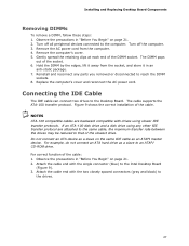
...anti-static package. 7. Gently spread the retaining clips at each end of the cable: 1. Replace the computer's cover and reconnect the AC power cord. Connecting the IDE Cable The IDE cable can connect two drives to an ATAPI CD-ROM drive. NOTES ATA-100 compatible cables are ...or disconnected to the drives. 27 Observe the precautions in "Before You Begin" on page 21. 2. Turn off all peripheral devices connected to the Intel Desktop Board (Figure 9). 3. The cable supports the ATA-100 transfer protocol. Attach the cable end with the single connector (blue) to the computer....
...anti-static package. 7. Gently spread the retaining clips at each end of the cable: 1. Replace the computer's cover and reconnect the AC power cord. Connecting the IDE Cable The IDE cable can connect two drives to an ATAPI CD-ROM drive. NOTES ATA-100 compatible cables are ...or disconnected to the drives. 27 Observe the precautions in "Before You Begin" on page 21. 2. Turn off all peripheral devices connected to the Intel Desktop Board (Figure 9). 3. The cable supports the ATA-100 transfer protocol. Attach the cable end with the single connector (blue) to the computer....

Product Guide
Page 31
...follow these steps: 1. Install a correctly keyed and shielded front panel audio cable. Observe the precautions in "Before You Begin" on page 30 for Intel High Definition Audio Pin Signal Name 1 PORT 1L 3 PORT 1R 5 PORT 2R 7 SENSE_SEND 9 PORT 2L Pin Signal Name 2 GND 4 PRESENCE... front panel audio header. Hi-Speed USB 2.0 Header Signal Names USB Port A USB Port B Pin Signal Name 1 Power 3 D- 5 D+ 7 Ground 9 Key Pin Signal Name 2 Power 4 D- 6 D+ 8 Ground 10 No connect Note: USB ports may be assigned as needed. 31 Installing and Replacing...
...follow these steps: 1. Install a correctly keyed and shielded front panel audio cable. Observe the precautions in "Before You Begin" on page 30 for Intel High Definition Audio Pin Signal Name 1 PORT 1L 3 PORT 1R 5 PORT 2R 7 SENSE_SEND 9 PORT 2L Pin Signal Name 2 GND 4 PRESENCE... front panel audio header. Hi-Speed USB 2.0 Header Signal Names USB Port A USB Port B Pin Signal Name 1 Power 3 D- 5 D+ 7 Ground 9 Key Pin Signal Name 2 Power 4 D- 6 D+ 8 Ground 10 No connect Note: USB ports may be assigned as needed. 31 Installing and Replacing...

Product Guide
Page 32
...4 HDR_BLNK_YEL Out Front panel yellow LED Reset Switch On/Off Switch 5 Ground Ground 6 SWITCH_ON# In Power switch 7 FP_RESET# In Reset switch 8 Ground Ground Power Not Connected 9 +5 V Power 10 N/C No pin Connecting a Chassis Fan Figure 12 shows the location of the chassis fan header. ...Table 6 shows the pin assignments for the location of the front panel header. Intel Desktop Board DG945GCLF Product Guide ...
...4 HDR_BLNK_YEL Out Front panel yellow LED Reset Switch On/Off Switch 5 Ground Ground 6 SWITCH_ON# In Power switch 7 FP_RESET# In Reset switch 8 Ground Ground Power Not Connected 9 +5 V Power 10 N/C No pin Connecting a Chassis Fan Figure 12 shows the location of the chassis fan header. ...Table 6 shows the pin assignments for the location of the front panel header. Intel Desktop Board DG945GCLF Product Guide ...

Product Guide
Page 33
Figure 13 shows the location of the power connectors. Figure 13. Connect the 12 V processor core voltage power supply cable to the 2 x 10 connector (Figure 13). 33 Connecting a 2 x 10 or 2 x 12 Power Supply Cable 1. Connect the main power supply cable (2 x 10 or 2 x 12) to the ...2 x 2 connector (Figure 13). 3. Installing and Replacing Desktop Board Components Connecting Power Supply Cables CAUTION Failure to use an appropriate power supply and/or not connecting the 12 V (2 x 2) power connector to the Desktop Board may not function properly. Observe the precautions in damage to...
Figure 13 shows the location of the power connectors. Figure 13. Connect the 12 V processor core voltage power supply cable to the 2 x 10 connector (Figure 13). 33 Connecting a 2 x 10 or 2 x 12 Power Supply Cable 1. Connect the main power supply cable (2 x 10 or 2 x 12) to the ...2 x 2 connector (Figure 13). 3. Installing and Replacing Desktop Board Components Connecting Power Supply Cables CAUTION Failure to use an appropriate power supply and/or not connecting the 12 V (2 x 2) power connector to the Desktop Board may not function properly. Observe the precautions in damage to...

Product Guide
Page 34
BIOS Configuration Jumper Block The three-pin BIOS jumper block enables all board configuration to be done in unreliable computer operation. Table 7 shows the jumper settings for the Setup program modes. 34 Intel Desktop Board DG945GCLF Product Guide Setting the BIOS Configuration Jumper NOTE Always turn off the power and unplug the power cord from the computer before changing a jumper. Figure 14 shows the location of the Desktop Board's BIOS configuration jumper block. Figure 14. Moving the jumper with the power on may result in the BIOS Setup program.
BIOS Configuration Jumper Block The three-pin BIOS jumper block enables all board configuration to be done in unreliable computer operation. Table 7 shows the jumper settings for the Setup program modes. 34 Intel Desktop Board DG945GCLF Product Guide Setting the BIOS Configuration Jumper NOTE Always turn off the power and unplug the power cord from the computer before changing a jumper. Figure 14 shows the location of the Desktop Board's BIOS configuration jumper block. Figure 14. Moving the jumper with the power on may result in the BIOS Setup program.

