
Product Specification
Page 5
......12 1.1.1 Feature Summary 12 1.1.2 Board Layout 13 1.1.3 Block Diagram 14 1.2 Online Support ...15 1.3 Design Specifications 16 1.4 Processor ...19 1.5 System Memory ...20 1.5.1 Memory Configurations 22 1.6 Intel® 865P Chipset ...24 1.6.1 Universal 0.8 V / 1.5 V AGP 3.0 Connector 24 1.6.2 USB...25 1.6.3 IDE Support 26 1.6.4 Real-... ALC202-based Audio Subsystem 28 1.8.2 Audio Connectors 28 1.8.3 Audio Subsystem Software 29 1.9 LAN Subsystem...29 1.9.1 Intel® 82562EZ Physical Layer Interface Device 29 1.9.2 RJ-45 LAN Connector with Integrated LEDs 30 1.9.3 LAN Subsystem...
......12 1.1.1 Feature Summary 12 1.1.2 Board Layout 13 1.1.3 Block Diagram 14 1.2 Online Support ...15 1.3 Design Specifications 16 1.4 Processor ...19 1.5 System Memory ...20 1.5.1 Memory Configurations 22 1.6 Intel® 865P Chipset ...24 1.6.1 Universal 0.8 V / 1.5 V AGP 3.0 Connector 24 1.6.2 USB...25 1.6.3 IDE Support 26 1.6.4 Real-... ALC202-based Audio Subsystem 28 1.8.2 Audio Connectors 28 1.8.3 Audio Subsystem Software 29 1.9 LAN Subsystem...29 1.9.1 Intel® 82562EZ Physical Layer Interface Device 29 1.9.2 RJ-45 LAN Connector with Integrated LEDs 30 1.9.3 LAN Subsystem...

Product Specification
Page 8
... LED Connector 53 25. Location of Single Channel Configuration without Dynamic Mode.....22 6. I /O Connectors 52 13. I/O Map ...38 13. Front Panel Audio Connector 47 18. Intel Desktop Board D865PCD Technical Product Specification Figures 1. Example of the Jumper Blocks 56 16. Back Panel Connectors 44 9. Audio Connectors ...46 10. Characteristics of Dual... Connector 49 22. Interrupts ...40 15. ATAPI CD-ROM Connector 47 17. Feature Summary...12 2. Block Diagram ...14 3. Example of Pressing the Power Switch 31 8. Processor Fan Connector 49 21.
... LED Connector 53 25. Location of Single Channel Configuration without Dynamic Mode.....22 6. I /O Connectors 52 13. I/O Map ...38 13. Front Panel Audio Connector 47 18. Intel Desktop Board D865PCD Technical Product Specification Figures 1. Example of the Jumper Blocks 56 16. Back Panel Connectors 44 9. Audio Connectors ...46 10. Characteristics of Dual... Connector 49 22. Interrupts ...40 15. ATAPI CD-ROM Connector 47 17. Feature Summary...12 2. Block Diagram ...14 3. Example of Pressing the Power Switch 31 8. Processor Fan Connector 49 21.

Product Specification
Page 11
1 Product Description What This Chapter Contains 1.1 Overview ...12 1.2 Online Support ...15 1.3 Design Specifications 16 1.4 Processor ...19 1.5 System Memory ...20 1.6 Intel® 865P Chipset ...24 1.7 I/O Controller ...27 1.8 Audio Subsystem...28 1.9 LAN Subsystem...29 1.10 Chassis Intrusion and Detection 30 1.11 Power Management 30 11
1 Product Description What This Chapter Contains 1.1 Overview ...12 1.2 Online Support ...15 1.3 Design Specifications 16 1.4 Processor ...19 1.5 System Memory ...20 1.6 Intel® 865P Chipset ...24 1.7 I/O Controller ...27 1.8 Audio Subsystem...28 1.9 LAN Subsystem...29 1.10 Chassis Intrusion and Detection 30 1.11 Power Management 30 11

Product Specification
Page 12
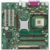
... (9.60 inches by 9.60 inches [243.84 millimeters by 243.84 millimeters]) Processor • Support for an Intel® Pentium® 4 processor in an mPGA478 socket with a 400 or 533 MHz system bus • Support for an Intel® Celeron® processor in card connectors (SMBus routed to PCI bus connector 2) For information about Available... Dual Inline Memory Module (DIMM) sockets • Support for DDR 333 and DDR 266 DIMMs • Support for up to 2 GB of system memory Chipset Intel® 865P Chipset, consisting of the Desktop Board D865PCD.
... (9.60 inches by 9.60 inches [243.84 millimeters by 243.84 millimeters]) Processor • Support for an Intel® Pentium® 4 processor in an mPGA478 socket with a 400 or 533 MHz system bus • Support for an Intel® Celeron® processor in card connectors (SMBus routed to PCI bus connector 2) For information about Available... Dual Inline Memory Module (DIMM) sockets • Support for DDR 333 and DDR 266 DIMMs • Support for up to 2 GB of system memory Chipset Intel® 865P Chipset, consisting of the Desktop Board D865PCD.

Product Specification
Page 13
... A Audio codec B Front panel audio connector C Ethernet PLC device (optional) D AGP connector E Rear chassis fan connector F Back panel connectors G +12V power connector (ATX12V) H mPGA478 processor socket I Processor fan connector J Intel 82865P MCH K DIMM Channel A socket L DIMM Channel B socket M I/O controller N Power connector OM17040 O Diskette drive connector P Parallel ATE IDE connectors Q Front chassis fan connector...
... A Audio codec B Front panel audio connector C Ethernet PLC device (optional) D AGP connector E Rear chassis fan connector F Back panel connectors G +12V power connector (ATX12V) H mPGA478 processor socket I Processor fan connector J Intel 82865P MCH K DIMM Channel A socket L DIMM Channel B socket M I/O controller N Power connector OM17040 O Diskette drive connector P Parallel ATE IDE connectors Q Front chassis fan connector...

Product Specification
Page 14
...Parallel ATA IDE Interface mPGA478 Processor Socket System Bus (400/533 MHz) USB LPC Bus I/O Controller LPC Bus Back Panel/ Front Panel USB Ports Serial Port Parallel Port PS/2 Mouse PS/2 Keyboard Diskette Drive Connector AGP Interface Universal 0.8/ 1.5 V AGP 3.0 Connector Intel 82865P Memory Controller Hub ...Channel B DIMM PCI Slot 1 PCI Slot 2 PCI Slot 3 Dual-Channel Memory Bus SMBus PCI Bus SMBus Intel 82801EB I/O Controller Hub (ICH5) 4 Mbit Firmware Hub (FWH) Intel 865P Chipset CSMA/CD Unit Interface 10/100 LAN PLC LAN Connector AC Link Line Out Realtek ALC202 Audio Codec ...
...Parallel ATA IDE Interface mPGA478 Processor Socket System Bus (400/533 MHz) USB LPC Bus I/O Controller LPC Bus Back Panel/ Front Panel USB Ports Serial Port Parallel Port PS/2 Mouse PS/2 Keyboard Diskette Drive Connector AGP Interface Universal 0.8/ 1.5 V AGP 3.0 Connector Intel 82865P Memory Controller Hub ...Channel B DIMM PCI Slot 1 PCI Slot 2 PCI Slot 3 Dual-Channel Memory Bus SMBus PCI Bus SMBus Intel 82801EB I/O Controller Hub (ICH5) 4 Mbit Firmware Hub (FWH) Intel 865P Chipset CSMA/CD Unit Interface 10/100 LAN PLC LAN Connector AC Link Line Out Realtek ALC202 Audio Codec ...

Product Specification
Page 15
... Support" Available configurations for the Desktop Board D865PCD Processor data sheets ICH5 addressing Custom splash screens Audio software and utilities LAN software and drivers Visit this World Wide Web site: http://www.intel.com/design/motherbd http://support.intel.com/support/motherboards/desktop http://developer.intel.com/design/motherbd/cd/cd_available.htm http://www...
... Support" Available configurations for the Desktop Board D865PCD Processor data sheets ICH5 addressing Custom splash screens Audio software and utilities LAN software and drivers Visit this World Wide Web site: http://www.intel.com/design/motherbd http://support.intel.com/support/motherboards/desktop http://developer.intel.com/design/motherbd/cd/cd_available.htm http://www...
Product Specification
Page 19
...; Do not use a standard ATX power supply. Product Description 1.4 Processor ✏ NOTE Refer to Thermal Considerations (Section 2.12, page 61) for important information when using an Intel Pentium 4 processor operating above . For information about Power supply connectors Refer to Table ...power supplies. The board is designed to support the following: • Intel Pentium 4 processors in an mPGA478 processor socket with a 400 or 533 MHz system bus • Intel Celeron processors in an mPGA478 processor socket with a standard ATX power supply. • Refer to Section ...
...; Do not use a standard ATX power supply. Product Description 1.4 Processor ✏ NOTE Refer to Thermal Considerations (Section 2.12, page 61) for important information when using an Intel Pentium 4 processor operating above . For information about Power supply connectors Refer to Table ...power supplies. The board is designed to support the following: • Intel Pentium 4 processors in an mPGA478 processor socket with a 400 or 533 MHz system bus • Intel Celeron processors in an mPGA478 processor socket with a standard ATX power supply. • Refer to Section ...

Product Specification
Page 20
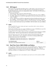
...function under the determined frequency. Supported System Bus Frequency and Memory Speed Combinations To use this type of DIMM... Table 3. DDR333 533 MHz DDR266 533 or 400 MHz ✏ NOTES • Remove the AGP video card before installing or upgrading ...Detect • DDR333 and DDR266 SDRAM DIMMs Table 3 lists the supported system bus frequency and memory speed combinations. For information about Obtaining DDR SDRAM specifications Refer to accurately configure memory settings for optimum performance. The processor's system bus frequency must be... Intel Desktop Board D865PCD...
...function under the determined frequency. Supported System Bus Frequency and Memory Speed Combinations To use this type of DIMM... Table 3. DDR333 533 MHz DDR266 533 or 400 MHz ✏ NOTES • Remove the AGP video card before installing or upgrading ...Detect • DDR333 and DDR266 SDRAM DIMMs Table 3 lists the supported system bus frequency and memory speed combinations. For information about Obtaining DDR SDRAM specifications Refer to accurately configure memory settings for optimum performance. The processor's system bus frequency must be... Intel Desktop Board D865PCD...
Product Specification
Page 26
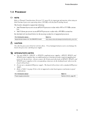
... (LBA) and Extended Cylinder Head Sector (ECHS) translation modes. floppy disk drive) • ARMD-HDD (ATAPI removable media device - Intel Desktop Board D865PCD Technical Product Specification 1.6.3 IDE Support The board provides two Parallel ATA IDE connectors, which support a total of the battery....of three years. The Parallel ATA IDE interfaces support the following modes: • Programmed I/O (PIO): processor controls data transfer. • 8237-style DMA: DMA offloads the processor, supporting transfer rates of up to 16 MB/sec. • Ultra DMA: DMA protocol on IDE ...
... (LBA) and Extended Cylinder Head Sector (ECHS) translation modes. floppy disk drive) • ARMD-HDD (ATAPI removable media device - Intel Desktop Board D865PCD Technical Product Specification 1.6.3 IDE Support The board provides two Parallel ATA IDE connectors, which support a total of the battery....of three years. The Parallel ATA IDE interfaces support the following modes: • Programmed I/O (PIO): processor controls data transfer. • 8237-style DMA: DMA offloads the processor, supporting transfer rates of up to 16 MB/sec. • Ultra DMA: DMA protocol on IDE ...

Product Specification
Page 32
...by the system chassis' power supply. 2. Dependent on the system configuration, including add-in the BIOS Setup program. Processor stopped S3 - Suspend to RAM. Soft off AC power is dependent on the standby power consumption of wake-up... 2) Power < 5 W (Note 2) Power < 5 W (Note 2) G3 - Notes: 1. Wake-up Devices and Events These devices/events can wake up event from specific states. Intel Desktop Board D865PCD Technical Product Specification Table 8. Power States and Targeted System Power Global States G0 - sleeping state G2/S5 Sleeping States S0 - working C1...
...by the system chassis' power supply. 2. Dependent on the system configuration, including add-in the BIOS Setup program. Processor stopped S3 - Suspend to RAM. Soft off AC power is dependent on the standby power consumption of wake-up... 2) Power < 5 W (Note 2) Power < 5 W (Note 2) G3 - Notes: 1. Wake-up Devices and Events These devices/events can wake up event from specific states. Intel Desktop Board D865PCD Technical Product Specification Table 8. Power States and Targeted System Power Global States G0 - sleeping state G2/S5 Sleeping States S0 - working C1...

Product Specification
Page 45
... support can access sensor data and other information residing on the Desktop Board. ✏ NOTE This document references back-panel slot numbering with respect to processor location on the board. The SMBus is not numbered. Figure 11 (page 51) illustrates the board's PCI slot numbering. 45 The AGP connector is keyed.... Do not install a legacy 3.3 V AGP card. Technical Reference 2.8.2 Internal I/O Connectors The internal I/O connectors are identified as PCI slot #x, starting with the slot closest to the processor.
... support can access sensor data and other information residing on the Desktop Board. ✏ NOTE This document references back-panel slot numbering with respect to processor location on the board. The SMBus is not numbered. Figure 11 (page 51) illustrates the board's PCI slot numbering. 45 The AGP connector is keyed.... Do not install a legacy 3.3 V AGP card. Technical Reference 2.8.2 Internal I/O Connectors The internal I/O connectors are identified as PCI slot #x, starting with the slot closest to the processor.

Product Specification
Page 48
A B 1 3 12 34 1 3 113 20 11 1 FE D C Item A B C D E F Description Rear chassis fan +12 V power connector (ATX12V) Processor fan Main power Front chassis fan Chassis intrusion For more information see: Table 18 Table 19 Table 20 Table 21 Table 22 Table 23 Figure 10. Power and Hardware Control Connectors OM17036 48 Intel Desktop Board D865PCD Technical Product Specification 2.8.2.3 Power and Hardware Control Connectors Figure 10 shows the location of the power and hardware control connectors.
A B 1 3 12 34 1 3 113 20 11 1 FE D C Item A B C D E F Description Rear chassis fan +12 V power connector (ATX12V) Processor fan Main power Front chassis fan Chassis intrusion For more information see: Table 18 Table 19 Table 20 Table 21 Table 22 Table 23 Figure 10. Power and Hardware Control Connectors OM17036 48 Intel Desktop Board D865PCD Technical Product Specification 2.8.2.3 Power and Hardware Control Connectors Figure 10 shows the location of the power and hardware control connectors.

Product Specification
Page 49
Processor Fan Connector Pin Signal Name 1 Control 2 +12 V 3 CPU_FAN_TACH Table 21. Main Power Connector Pin Signal Name 1 +3.3 V 2 +3.3 V 3 Ground 4 +5 V 5 Ground 6 +5 V 7 Ground 8 PWRGD (Power Good) 9 +5 V (Standby) 10 +12 V ... not boot with the Desktop Board D865PCD. ATX12V, SFX12V, and TFX12V power supplies have an additional power lead that provides required supplemental power for the processor. Technical Reference Table 18. The board will not boot. • Do not use a standard ATX power supply. Always connect the 20-pin and 4-pin leads...
Processor Fan Connector Pin Signal Name 1 Control 2 +12 V 3 CPU_FAN_TACH Table 21. Main Power Connector Pin Signal Name 1 +3.3 V 2 +3.3 V 3 Ground 4 +5 V 5 Ground 6 +5 V 7 Ground 8 PWRGD (Power Good) 9 +5 V (Standby) 10 +12 V ... not boot with the Desktop Board D865PCD. ATX12V, SFX12V, and TFX12V power supplies have an additional power lead that provides required supplemental power for the processor. Technical Reference Table 18. The board will not boot. • Do not use a standard ATX power supply. Always connect the 20-pin and 4-pin leads...

Product Specification
Page 52
...install a legacy 3.3 V AGP card. The AGP connector is keyed for Universal 0.8 V AGP 3.0 cards or 1.5 V AGP 2.0 cards only. Intel Desktop Board D865PCD Technical Product Specification # INTEGRATOR'S NOTES • The AGP connector is not mechanically compatible with legacy 3.3 V AGP cards. •...be used in PCI bus connector 3. 2.8.3 External I/O Connectors Figure 12 shows the locations of the external I /O Connectors 52 Do not attempt to the processor). External I /O connectors. 2 1 C 7 10 1 2 B 8 913 Item A B C A Description Auxiliary front panel power/sleep/message-...
...install a legacy 3.3 V AGP card. The AGP connector is keyed for Universal 0.8 V AGP 3.0 cards or 1.5 V AGP 2.0 cards only. Intel Desktop Board D865PCD Technical Product Specification # INTEGRATOR'S NOTES • The AGP connector is not mechanically compatible with legacy 3.3 V AGP cards. •...be used in PCI bus connector 3. 2.8.3 External I/O Connectors Figure 12 shows the locations of the external I /O Connectors 52 Do not attempt to the processor). External I /O connectors. 2 1 C 7 10 1 2 B 8 913 Item A B C A Description Auxiliary front panel power/sleep/message-...

Product Specification
Page 57
.... When the jumper is set to configure mode and the computer is displayed. Table 29. The 3 maintenance menu is powered-up, the BIOS compares the processor version and the microcode version in the BIOS and reports if the two match. The back panel audio line out connector is required. 57 A 3 recovery...
.... When the jumper is set to configure mode and the computer is displayed. Table 29. The 3 maintenance menu is powered-up, the BIOS compares the processor version and the microcode version in the BIOS and reports if the two match. The back panel audio line out connector is required. 57 A 3 recovery...

Product Specification
Page 60
... The boards are based on the board that impact its power delivery subsystems. The analysis does not include PCI add-in cards. Intel Desktop Board D865PCD Technical Product Specification 2.11 Electrical Considerations 2.11.1 DC Loading Table 30 lists the DC loading characteristics of the fan... connectors. This data is similar to the processor, memory, and USB ports. Maximum values assume a load placed on the minimum and maximum current draw possible from the board's power delivery...
... The boards are based on the board that impact its power delivery subsystems. The analysis does not include PCI add-in cards. Intel Desktop Board D865PCD Technical Product Specification 2.11 Electrical Considerations 2.11.1 DC Loading Table 30 lists the DC loading characteristics of the fan... connectors. This data is similar to the processor, memory, and USB ports. Maximum values assume a load placed on the minimum and maximum current draw possible from the board's power delivery...

Product Specification
Page 61
...integrators should refer to the power usage values listed in Table 30 when selecting a power supply for use of an Intel Pentium 4 processor operating above 2.80 GHz with this document will depend on the wake devices supported and manufacturing options. Additional power required ... result in reduced performance of both the processor and/or voltage regulator or, in a system with the reader. For a list of chassis that merely following recommendations found in this Intel desktop board requires the following website: http://developer.intel.com/design/motherbd/cooling.htm All responsibility...
...integrators should refer to the power usage values listed in Table 30 when selecting a power supply for use of an Intel Pentium 4 processor operating above 2.80 GHz with this document will depend on the wake devices supported and manufacturing options. Additional power required ... result in reduced performance of both the processor and/or voltage regulator or, in a system with the reader. For a list of chassis that merely following recommendations found in this Intel desktop board requires the following website: http://developer.intel.com/design/motherbd/cooling.htm All responsibility...

Product Specification
Page 62
... circuit. CAUTION Ensure that the ambient temperature does not exceed the Desktop Board's maximum operating temperature. The processor voltage regulator area (item A in an open chassis. A B C D Item A B C D Description Processor voltage regulator area Processor Intel 82865P MCH Intel 82801EB ICH5 OM17041 Figure 18. For information about the maximum operating temperature, see the environmental specifications in the...
... circuit. CAUTION Ensure that the ambient temperature does not exceed the Desktop Board's maximum operating temperature. The processor voltage regulator area (item A in an open chassis. A B C D Item A B C D Description Processor voltage regulator area Processor Intel 82865P MCH Intel 82801EB ICH5 OM17041 Figure 18. For information about the maximum operating temperature, see the environmental specifications in the...
Product Specification
Page 63
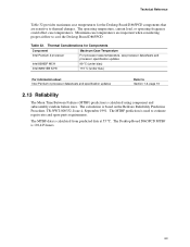
.... Technical Reference Table 32 provides maximum case temperatures for Components Component Intel Pentium 4 processor Intel 82865P MCH Intel 82801EB ICH5 Maximum Case Temperature For processor case temperature, see processor datasheets and processor specification updates 99 oC (under bias) 115 oC (under bias) For information about Intel Pentium 4 processor datasheets and specification updates Refer to Section 1.2, page 15 2.13 Reliability...
.... Technical Reference Table 32 provides maximum case temperatures for Components Component Intel Pentium 4 processor Intel 82865P MCH Intel 82801EB ICH5 Maximum Case Temperature For processor case temperature, see processor datasheets and processor specification updates 99 oC (under bias) 115 oC (under bias) For information about Intel Pentium 4 processor datasheets and specification updates Refer to Section 1.2, page 15 2.13 Reliability...


