Product Guide
Page 5
...Support 19 Battery ...22 Real-Time Clock 22 2 Installing and Replacing Desktop Board Components Before You Begin 23 Installation Precautions 25 Prevent Power Supply Overload 25 Observe Safety and Regulatory Requirements 25 Installing the I/O Shield 26 Installing and Removing the Desktop Board 27 Installing and ...Removing Memory 28 Connecting SATA Drives 29 Installing a Wireless LAN Card in the PCI Express Mini Card Slot 30 Installing an Intel® Z-U130 USB Solid-State Drive or Compatible Device 32 Connecting to the Internal Headers 33 Connecting to the Front Panel Audio...
...Support 19 Battery ...22 Real-Time Clock 22 2 Installing and Replacing Desktop Board Components Before You Begin 23 Installation Precautions 25 Prevent Power Supply Overload 25 Observe Safety and Regulatory Requirements 25 Installing the I/O Shield 26 Installing and Removing the Desktop Board 27 Installing and ...Removing Memory 28 Connecting SATA Drives 29 Installing a Wireless LAN Card in the PCI Express Mini Card Slot 30 Installing an Intel® Z-U130 USB Solid-State Drive or Compatible Device 32 Connecting to the Internal Headers 33 Connecting to the Front Panel Audio...

Product Guide
Page 6
... D525MW Product Guide 3 Updating the BIOS Updating the BIOS with the Intel® Express BIOS Update Utility 47 Updating the BIOS with the Iflash Memory Update Utility 48 Obtaining the BIOS Update File 48 Using the Iflash ...Memory Update Utility 48 Recovering the BIOS 49 A Board Status and Error Messages BIOS Beep Codes 51 BIOS Front-panel Power LED Blink Codes 52 POST Error Messages 52 B Regulatory Compliance Safety Standards 53 Battery Caution 53 European Union Declaration of Conformity Statement 54 Product Ecology...
... D525MW Product Guide 3 Updating the BIOS Updating the BIOS with the Intel® Express BIOS Update Utility 47 Updating the BIOS with the Iflash Memory Update Utility 48 Obtaining the BIOS Update File 48 Using the Iflash ...Memory Update Utility 48 Recovering the BIOS 49 A Board Status and Error Messages BIOS Beep Codes 51 BIOS Front-panel Power LED Blink Codes 52 POST Error Messages 52 B Regulatory Compliance Safety Standards 53 Battery Caution 53 European Union Declaration of Conformity Statement 54 Product Ecology...

Product Guide
Page 7
...Jumper Settings for AC '97 Audio 34 7. BIOS Front-panel Power LED Blink Codes 52 17. Installing a Full-Mini Card Wireless LAN Card 30 10. Internal Headers 33 13. Intel Desktop Board D525MW China RoHS Material Self Declaration Table 58 Tables.... Installing the I/O Shield 26 6. Location of the Standby Power Indicator 20 5. Serial Port Header (COM 1 35 9. Intel Desktop Board D525MW Mounting Screw Holes 27 7. Connecting Power Supply Cables 38 15. AcceptableDrives/Media Types for Intel HD Audio 34 6. Regulatory Compliance Marks 62 21. Installing ...
...Jumper Settings for AC '97 Audio 34 7. BIOS Front-panel Power LED Blink Codes 52 17. Installing a Full-Mini Card Wireless LAN Card 30 10. Internal Headers 33 13. Intel Desktop Board D525MW China RoHS Material Self Declaration Table 58 Tables.... Installing the I/O Shield 26 6. Location of the Standby Power Indicator 20 5. Serial Port Header (COM 1 35 9. Intel Desktop Board D525MW Mounting Screw Holes 27 7. Connecting Power Supply Cables 38 15. AcceptableDrives/Media Types for Intel HD Audio 34 6. Regulatory Compliance Marks 62 21. Installing ...
Product Guide
Page 10
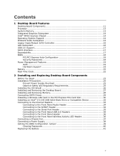
.../support/go/buildit 10 Visit this World Wide Web site: Intel Desktop Board D525MW http://www.intel.com/products/motherboard/index.htm Desktop Board Support http://www.intel.com/p/en_US/support?iid=hdr+support Available configurations for Advanced Configuration and Power Interface (ACPI) • Wake on USB, PCI, PCI Express, PS/2, LAN, serial, and...
.../support/go/buildit 10 Visit this World Wide Web site: Intel Desktop Board D525MW http://www.intel.com/products/motherboard/index.htm Desktop Board Support http://www.intel.com/p/en_US/support?iid=hdr+support Available configurations for Advanced Configuration and Power Interface (ACPI) • Wake on USB, PCI, PCI Express, PS/2, LAN, serial, and...

Product Guide
Page 13
... recommended above the processor heatsink area for DDR3 800/1066/1333 MHz SO-DIMMs (DDR3 1066 MHz and DDR3 1333 MHz SO-DIMMs operate at power up. The BIOS will see a notification to this effect on the screen at 800 MHz only) • Serial Presence Detect (SPD) memory...modules do not support SPD, you will attempt to be populated with gold-plated contacts. System Memory NOTE To be fully compliant with all applicable Intel® SDRAM memory specifications, the board should be passively cooled in a properly ventilated chassis. These sockets support: • Support for maximum heat...
... recommended above the processor heatsink area for DDR3 800/1066/1333 MHz SO-DIMMs (DDR3 1066 MHz and DDR3 1333 MHz SO-DIMMs operate at power up. The BIOS will see a notification to this effect on the screen at 800 MHz only) • Serial Presence Detect (SPD) memory...modules do not support SPD, you will attempt to be populated with gold-plated contacts. System Memory NOTE To be fully compliant with all applicable Intel® SDRAM memory specifications, the board should be passively cooled in a properly ventilated chassis. These sockets support: • Support for maximum heat...
Product Guide
Page 15
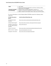
... (non-amplified) speakers are configurable through the audio device drivers. Pink Back panel - Desktop Board Features The front/back panel audio connectors are connected to power headphones or amplified speakers only.
... (non-amplified) speakers are configurable through the audio device drivers. Pink Back panel - Desktop Board Features The front/back panel audio connectors are connected to power headphones or amplified speakers only.
Product Guide
Page 16
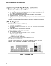
... LAN subsystem include: • CSMA/CD protocol engine • LAN connect interface that supports the ethernet controller • PCI bus power management ⎯ Supports ACPI technology ⎯ Supports LAN wake capabilities LAN drivers are built into the RJ-45 LAN connector located on... the back panel (see Figure 3). LAN Status LEDs 16 Figure 3. Two LEDs are available from Intel's World Wide Web site at http://downloadcenter.intel.com/. Intel Desktop Board D525MW Product Guide Legacy Input/Output (I/O) Controller The legacy I/O controller provides the following : •...
... LAN subsystem include: • CSMA/CD protocol engine • LAN connect interface that supports the ethernet controller • PCI bus power management ⎯ Supports ACPI technology ⎯ Supports LAN wake capabilities LAN drivers are built into the RJ-45 LAN connector located on... the back panel (see Figure 3). LAN Status LEDs 16 Figure 3. Two LEDs are available from Intel's World Wide Web site at http://downloadcenter.intel.com/. Intel Desktop Board D525MW Product Guide Legacy Input/Output (I/O) Controller The legacy I/O controller provides the following : •...

Product Guide
Page 17
...USB 2.0 Support The Desktop Board supports up and the LAN subsystem is attached to the cable. One of the front panel USB headers supports an Intel Z-U130 USB Solid-State Drive or compatible device. USB 2.0 support requires both legacy and native modes. This may be required to accommodate operating ...systems that support one device per channel. Desktop Board Features Table 4 describes the LED states when the board is powered up to seven USB 2.0 ports (four ports routed to the back panel and three ports routed to two front panel USB 2.0 headers). or...
...USB 2.0 Support The Desktop Board supports up and the LAN subsystem is attached to the cable. One of the front panel USB headers supports an Intel Z-U130 USB Solid-State Drive or compatible device. USB 2.0 support requires both legacy and native modes. This may be required to accommodate operating ...systems that support one device per channel. Desktop Board Features Table 4 describes the LED states when the board is powered up to seven USB 2.0 ports (four ports routed to the back panel and three ports routed to two front panel USB 2.0 headers). or...
Product Guide
Page 18
... set , you install a PCI/PCI Express add-in card. Security Passwords The BIOS includes security features that add-in card. Intel Desktop Board D525MW Product Guide BIOS The BIOS provides the Power-On Self-Test (POST), the BIOS Setup program, the PCI and SATA auto-configuration utilities, and the video BIOS. If...
... set , you install a PCI/PCI Express add-in card. Security Passwords The BIOS includes security features that add-in card. Intel Desktop Board D525MW Product Guide BIOS The BIOS provides the Power-On Self-Test (POST), the BIOS Setup program, the PCI and SATA auto-configuration utilities, and the video BIOS. If...

Product Guide
Page 19
...wakeup support ― WAKE# signal wakeup support ― Wake from serial port ACPI ACPI gives the operating system direct control over the power management and Plug and Play functions of ACPI with the Desktop Board requires an operating system that provides full ACPI support. The use ...a computer. Hardware Support Fan Header The Desktop Board has a 3-pin chassis fan header. Desktop Board Features Power Management Features Power management is still lit, disconnect the power cord before installing or removing any attached devices. Failure to do so could damage the board and any devices ...
...wakeup support ― WAKE# signal wakeup support ― Wake from serial port ACPI ACPI gives the operating system direct control over the power management and Plug and Play functions of ACPI with the Desktop Board requires an operating system that provides full ACPI support. The use ...a computer. Hardware Support Fan Header The Desktop Board has a 3-pin chassis fan header. Desktop Board Features Power Management Features Power management is still lit, disconnect the power cord before installing or removing any attached devices. Failure to do so could damage the board and any devices ...

Product Guide
Page 20
While in power management and can participate in the ACPI S3 sleep-state, the computer will appear to be used to the Technical Product Specification on the Intel Desktop D525MW web page at http://www.intel.com/products/motherboard/D525MW/index.htm. Instantly Available PC Technology... PCI 2.3 compliant add-in cards and drivers. 20 The board supports the PCI Bus Power Management Interface Specification. Intel Desktop Board D525MW Product Guide Figure 4. The use of the Standby Power Indicator For more information on standby current requirements for the Desktop Board, refer to wake ...
While in power management and can participate in the ACPI S3 sleep-state, the computer will appear to be used to the Technical Product Specification on the Intel Desktop D525MW web page at http://www.intel.com/products/motherboard/D525MW/index.htm. Instantly Available PC Technology... PCI 2.3 compliant add-in cards and drivers. 20 The board supports the PCI Bus Power Management Interface Specification. Intel Desktop Board D525MW Product Guide Figure 4. The use of the Standby Power Indicator For more information on standby current requirements for the Desktop Board, refer to wake ...

Product Guide
Page 21
..., S3, S4, or S5 state. The board supports LAN wake capabilities with ACPI in an ACPI S4 or S5 state, the only PS/2 activity that powers up of a USB peripheral that supports wake from USB. Wake from PS/2 Device PS/2 keyboard activity wakes the computer from an ACPI S1 or S3... the configured wake packet type, the LAN subsystem asserts a wakeup signal that will wake the computer is the Alt + Print Screen key combination or the Power key available only on the PCI bus, the computer wakes from an ACPI S1, S3, S4, or S5 state. NOTE Wake from an ACPI S1...
..., S3, S4, or S5 state. The board supports LAN wake capabilities with ACPI in an ACPI S4 or S5 state, the only PS/2 activity that powers up of a USB peripheral that supports wake from USB. Wake from PS/2 Device PS/2 keyboard activity wakes the computer from an ACPI S1 or S3... the configured wake packet type, the LAN subsystem asserts a wakeup signal that will wake the computer is the Alt + Print Screen key combination or the Power key available only on the PCI bus, the computer wakes from an ACPI S1, S3, S4, or S5 state. NOTE Wake from an ACPI S1...

Product Guide
Page 23
... any procedures can result in this chapter only at an ESD workstation using and modifying electronic equipment. Disconnect the computer from its power source and from any telecommunications links, networks, or modems before you begin installing the Desktop Board: • Always follow the ...8226; Connect SATA drives • Install a Wireless LAN card • Install an Intel Z-U130 USB Solid-State Drive or compatible device • Connect to operate even though the front panel power button is not available, you can provide some ESD protection by wearing an antistatic wrist...
... any procedures can result in this chapter only at an ESD workstation using and modifying electronic equipment. Disconnect the computer from its power source and from any telecommunications links, networks, or modems before you begin installing the Desktop Board: • Always follow the ...8226; Connect SATA drives • Install a Wireless LAN card • Install an Intel Z-U130 USB Solid-State Drive or compatible device • Connect to operate even though the front panel power button is not available, you can provide some ESD protection by wearing an antistatic wrist...

Product Guide
Page 25
... module suppliers, you increase safety risk and the possibility of noncompliance with the chassis and associated modules. To avoid overloading the power supply, make sure that instruct you to refer computer servicing to wires that could cause a short circuit Observe all warnings and...Components Installation Precautions When you install and test the Intel Desktop Board, observe all the modules within the computer is less than the output current rating of the power supply. Prevent Power Supply Overload Do not overload the power supply output. Observe Safety and Regulatory Requirements Read...
... module suppliers, you increase safety risk and the possibility of noncompliance with the chassis and associated modules. To avoid overloading the power supply, make sure that instruct you to refer computer servicing to wires that could cause a short circuit Observe all warnings and...Components Installation Precautions When you install and test the Intel Desktop Board, observe all the modules within the computer is less than the output current rating of the power supply. Prevent Power Supply Overload Do not overload the power supply output. Observe Safety and Regulatory Requirements Read...

Product Guide
Page 27
... of the mounting screw holes for instructions on installing and removing the Desktop Board. Intel Desktop Board D525MW Mounting Screw Holes 27 Failure to your chassis manual for Intel Desktop Board D525MW. Disconnect the computer from its power source before you open the computer can result in personal injury or equipment damage. Installing...
... of the mounting screw holes for instructions on installing and removing the Desktop Board. Intel Desktop Board D525MW Mounting Screw Holes 27 Failure to your chassis manual for Intel Desktop Board D525MW. Disconnect the computer from its power source before you open the computer can result in personal injury or equipment damage. Installing...

Product Guide
Page 36
Intel Desktop Board D525MW Product Guide Connecting to the Front Panel Header...LED (+) 2 Ground 36 Front Panel Header Signal Names Pin Signal In/Out Description Pin Signal In/Out Hard Drive Activity LED Power LED 1 HD_PWR Out Hard disk LED pullup (330 Ω) to +5 V 2 HDR_BLNK_GRN Out 3 HDA# Out Hard disk... Switch On/Off Switch 5 Ground 7 FP_RESET# In Ground Reset switch 6 SWITCH_ON# In 8 Ground Power switch Ground Power Not Connected 9 +5 V Power 10 N/C No pin Connecting to the Front Panel Wireless Activity LED Header Before connecting to the front panel...
Intel Desktop Board D525MW Product Guide Connecting to the Front Panel Header...LED (+) 2 Ground 36 Front Panel Header Signal Names Pin Signal In/Out Description Pin Signal In/Out Hard Drive Activity LED Power LED 1 HD_PWR Out Hard disk LED pullup (330 Ω) to +5 V 2 HDR_BLNK_GRN Out 3 HDA# Out Hard disk... Switch On/Off Switch 5 Ground 7 FP_RESET# In Ground Reset switch 6 SWITCH_ON# In 8 Ground Power switch Ground Power Not Connected 9 +5 V Power 10 N/C No pin Connecting to the Front Panel Wireless Activity LED Header Before connecting to the front panel...

Product Guide
Page 38
Connecting Power Supply Cables 1. Figure 14. Connect the main power supply cable to the 2 x 2 pin connector (Figure 14, A). 38 Connect the 12 V processor core voltage power supply cable to the 2 x 12 pin connector (Figure 14, B). 3. Figure 14 shows the location of the power connectors. Intel Desktop Board D525MW Product Guide Connecting a Power Supply CAUTION Failure to connect an appropriate power supply to the Desktop Board may not function properly. Observe the precautions in damage to the board or the system may result in "Before You Begin" on page 23. 2.
Connecting Power Supply Cables 1. Figure 14. Connect the main power supply cable to the 2 x 2 pin connector (Figure 14, A). 38 Connect the 12 V processor core voltage power supply cable to the 2 x 12 pin connector (Figure 14, B). 3. Figure 14 shows the location of the power connectors. Intel Desktop Board D525MW Product Guide Connecting a Power Supply CAUTION Failure to connect an appropriate power supply to the Desktop Board may not function properly. Observe the precautions in damage to the board or the system may result in "Before You Begin" on page 23. 2.

Product Guide
Page 39
Figure 15. Moving the jumper with the power on may result in unreliable computer operation. Table 13 shows the jumper settings for each of the Desktop Board's BIOS configuration jumper block. BIOS Configuration Jumper Block The three-pin BIOS configuration jumper block enables board operating modes. Figure 15 shows the location of the available modes. 39 Installing and Replacing Desktop Board Components Setting the BIOS Configuration Jumper NOTE Always turn off the power and unplug the power cord from the computer before changing a jumper.
Figure 15. Moving the jumper with the power on may result in unreliable computer operation. Table 13 shows the jumper settings for each of the Desktop Board's BIOS configuration jumper block. BIOS Configuration Jumper Block The three-pin BIOS configuration jumper block enables board operating modes. Figure 15 shows the location of the available modes. 39 Installing and Replacing Desktop Board Components Setting the BIOS Configuration Jumper NOTE Always turn off the power and unplug the power cord from the computer before changing a jumper.

Product Guide
Page 40
... the precautions in the computer, turn on the computer, and allow it to normal mode. 1. Place the jumper on page 23. 2. Intel Desktop Board D525MW Product Guide Figure 15 shows the location of a failed BIOS update. Remove the computer cover. 4. The computer starts the ... Select Yes and press . Turn off all peripheral devices connected to save the current values and exit Setup. 10. Disconnect the computer's power cord from a recovery diskette in the computer and the configuration jumper is installed in the event of the Desktop Board's BIOS configuration jumper...
... the precautions in the computer, turn on the computer, and allow it to normal mode. 1. Place the jumper on page 23. 2. Intel Desktop Board D525MW Product Guide Figure 15 shows the location of a failed BIOS update. Remove the computer cover. 4. The computer starts the ... Select Yes and press . Turn off all peripheral devices connected to save the current values and exit Setup. 10. Disconnect the computer's power cord from a recovery diskette in the computer and the configuration jumper is installed in the event of the Desktop Board's BIOS configuration jumper...

Product Guide
Page 41
Replacing the Battery A coin-cell battery powers the Desktop Board's real-time clock and CMOS memory. The clock is replaced with 3.3 VSB applied. CAUTION Risk of explosion if the battery is accurate ... une pile de type incorrect. VARO Räjähdysvaara, jos pariston tyyppi on the computer. Replace the cover, plug in , the standby current from the power supply extends the life of three years. When the voltage drops below . 13. Figure 16 on mahdollista. Risk för explosion om batteriet ersätts...
Replacing the Battery A coin-cell battery powers the Desktop Board's real-time clock and CMOS memory. The clock is replaced with 3.3 VSB applied. CAUTION Risk of explosion if the battery is accurate ... une pile de type incorrect. VARO Räjähdysvaara, jos pariston tyyppi on the computer. Replace the cover, plug in , the standby current from the power supply extends the life of three years. When the voltage drops below . 13. Figure 16 on mahdollista. Risk för explosion om batteriet ersätts...

