
Product Specification
Page 5
... Block Diagram 16 1.2 Online Support 17 1.3 Processor 17 1.4 System Memory 18 1.4.1 Memory Configurations 20 1.5 Intel® Virtualization Technology (Intel® VT 26 1.6 Intel® vPro™ Technology Support 27 1.7 Intel® Q965 Express Chipset 28 1.7.1 Intel Q965 Graphics Subsystem 28 1.7.2 USB 30 1.7.3 Serial ATA Interfaces 31 ... 36 1.10.2 LAN Subsystem Software 36 1.10.3 RJ-45 LAN Connector with Integrated LEDs 37 1.10.4 Intel® Active Management Technology (Intel® AMT) with System Defense Feature 37 1.10.5 Alert Standard Format (ASF) 2.0 Support 38 1.11...
... Block Diagram 16 1.2 Online Support 17 1.3 Processor 17 1.4 System Memory 18 1.4.1 Memory Configurations 20 1.5 Intel® Virtualization Technology (Intel® VT 26 1.6 Intel® vPro™ Technology Support 27 1.7 Intel® Q965 Express Chipset 28 1.7.1 Intel Q965 Graphics Subsystem 28 1.7.2 USB 30 1.7.3 Serial ATA Interfaces 31 ... 36 1.10.2 LAN Subsystem Software 36 1.10.3 RJ-45 LAN Connector with Integrated LEDs 37 1.10.4 Intel® Active Management Technology (Intel® AMT) with System Defense Feature 37 1.10.5 Alert Standard Format (ASF) 2.0 Support 38 1.11...
Product Specification
Page 6
Intel Desktop Board DQ965GF Technical Product Specification 2 Technical Reference 2.1 Memory Map 49 2.1.1 Addressable Memory 49 2.2 DMA Channels 51 2.3 Fixed I/O Map 52 2.4 PCI Configuration Space Map 53 2.5 Interrupts 54 2.6 PCI Interrupt ...Power Supply Considerations 74 2.11 Thermal Considerations 75 2.12 Reliability 77 2.13 Environmental 78 3 Overview of BIOS Features 3.1 Introduction 79 3.2 BIOS Flash Memory Organization 80 3.3 Resource Configuration 80 3.3.1 PCI Autoconfiguration 80 3.3.2 PCI IDE Support 81 3.4 System Management BIOS (SMBIOS 81 3.5 Legacy USB Support ...
Intel Desktop Board DQ965GF Technical Product Specification 2 Technical Reference 2.1 Memory Map 49 2.1.1 Addressable Memory 49 2.2 DMA Channels 51 2.3 Fixed I/O Map 52 2.4 PCI Configuration Space Map 53 2.5 Interrupts 54 2.6 PCI Interrupt ...Power Supply Considerations 74 2.11 Thermal Considerations 75 2.12 Reliability 77 2.13 Environmental 78 3 Overview of BIOS Features 3.1 Introduction 79 3.2 BIOS Flash Memory Organization 80 3.3 Resource Configuration 80 3.3.1 PCI Autoconfiguration 80 3.3.2 PCI IDE Support 81 3.4 System Management BIOS (SMBIOS 81 3.5 Legacy USB Support ...
Product Specification
Page 7
... Board Components 14 2. Thermal Sensors and Fan Headers 40 13. Connection Diagram for IEEE-1394a Header 66 20. Location of the Jumper Block 67 21. Memory Channel Configuration and DIMM Configuration 21 4. Flex Mode Configuration with Four DIMMs 23 7. LAN Connector LED Locations 37 12. Board Dimensions 68 22. Localized High... DIMM .......... 24 8. Connection Diagram for Boards with IEEE-1394a and PS/2 Connectors 70 23. I/O Shield Dimensions for Front Panel USB Headers 66 19. Detailed System Memory Address Map 50 15. Back Panel Connectors 57 16.
... Board Components 14 2. Thermal Sensors and Fan Headers 40 13. Connection Diagram for IEEE-1394a Header 66 20. Location of the Jumper Block 67 21. Memory Channel Configuration and DIMM Configuration 21 4. Flex Mode Configuration with Four DIMMs 23 7. LAN Connector LED Locations 37 12. Board Dimensions 68 22. Localized High... DIMM .......... 24 8. Connection Diagram for Boards with IEEE-1394a and PS/2 Connectors 70 23. I/O Shield Dimensions for Front Panel USB Headers 66 19. Detailed System Memory Address Map 50 15. Back Panel Connectors 57 16.
Product Specification
Page 8
...Front Panel Audio Header 61 25. Processor Core Power Connector 63 26. System Memory Map 51 12. States for a One-Color Power LED 65 29. Boot Device Menu Options 84 41. Supported Memory Configurations 18 5. Audio Jack Retasking Support 34 7. Wake-up Devices and Events... 43 11. States for a Two-Color Power LED 65 30. Compatible I /O Map 52 14. Acceptable Drives/Media Types for Components 77 36. Port 80h POST Code Ranges 88 45. Typical Port 80h POST Sequence 92 viii Intel...
...Front Panel Audio Header 61 25. Processor Core Power Connector 63 26. System Memory Map 51 12. States for a One-Color Power LED 65 29. Boot Device Menu Options 84 41. Supported Memory Configurations 18 5. Audio Jack Retasking Support 34 7. Wake-up Devices and Events... 43 11. States for a Two-Color Power LED 65 30. Compatible I /O Map 52 14. Acceptable Drives/Media Types for Components 77 36. Port 80h POST Code Ranges 88 45. Typical Port 80h POST Sequence 92 viii Intel...

Product Specification
Page 11
1 Product Description What This Chapter Contains 1.1 Overview 12 1.2 Online Support 17 1.3 Processor 17 1.4 System Memory 18 1.5 Intel® Virtualization Technology (Intel® VT 26 1.6 Intel® vPro™ Technology Support 27 1.7 Intel® Q965 Express Chipset 28 1.8 Legacy I/O Controller 33 1.9 Audio Subsystem 34 1.10 LAN Subsystem 36 1.11 Hardware Management Subsystem 39 1.12 Power Management 41 1.13 Trusted Platform Module (TPM 48 11
1 Product Description What This Chapter Contains 1.1 Overview 12 1.2 Online Support 17 1.3 Processor 17 1.4 System Memory 18 1.5 Intel® Virtualization Technology (Intel® VT 26 1.6 Intel® vPro™ Technology Support 27 1.7 Intel® Q965 Express Chipset 28 1.8 Legacy I/O Controller 33 1.9 Audio Subsystem 34 1.10 LAN Subsystem 36 1.11 Hardware Management Subsystem 39 1.12 Power Management 41 1.13 Trusted Platform Module (TPM 48 11

Product Specification
Page 12
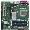
... Board DQ965GF Technical Product Specification 1.1 Overview 1.1.1 Feature Summary Table 1 summarizes the major features of : • Intel® 82Q965 Graphics Memory Controller Hub (GMCH) • Intel® 82801HO I/O Controller Hub (ICH8DO) Intel® GMA 3000 onboard graphics subsystem Audio Legacy I/O Control USB Peripheral Interfaces LAN Support BIOS Trusted Platform Module (TPM), revision 1.2 6-channel (5.1) audio subsystem...
... Board DQ965GF Technical Product Specification 1.1 Overview 1.1.1 Feature Summary Table 1 summarizes the major features of : • Intel® 82Q965 Graphics Memory Controller Hub (GMCH) • Intel® 82801HO I/O Controller Hub (ICH8DO) Intel® GMA 3000 onboard graphics subsystem Audio Legacy I/O Control USB Peripheral Interfaces LAN Support BIOS Trusted Platform Module (TPM), revision 1.2 6-channel (5.1) audio subsystem...
Product Specification
Page 16
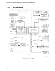
...Parallel ATA IDE Controller System Bus (1066/800/533 MHz) PCI Express x16 Connector Intel Q965 Express Chipset PCI Express x16 Interface Display Interface Intel 82Q965 Graphics and Memory Controller Hub (GMCH) Gigabit Ethernet Controller LAN Connector USB Back Panel/Front Panel USB... PS/2 Mouse* PS/2 Keyboard* LPC Bus Diskette Drive Connector Intel 82801HO I/O Controller Hub (ICH8DO) Serial Peripheral Interface (SPI) Flash Device DMI Interconnect VGA Port Channel A DIMMs (2) Channel B DIMMs (2) Dual-Channel Memory Bus SMBus LPC Bus TPM Component Serial ATA IDE Interface Serial...
...Parallel ATA IDE Controller System Bus (1066/800/533 MHz) PCI Express x16 Connector Intel Q965 Express Chipset PCI Express x16 Interface Display Interface Intel 82Q965 Graphics and Memory Controller Hub (GMCH) Gigabit Ethernet Controller LAN Connector USB Back Panel/Front Panel USB... PS/2 Mouse* PS/2 Keyboard* LPC Bus Diskette Drive Connector Intel 82801HO I/O Controller Hub (ICH8DO) Serial Peripheral Interface (SPI) Flash Device DMI Interconnect VGA Port Channel A DIMMs (2) Channel B DIMMs (2) Dual-Channel Memory Bus SMBus LPC Bus TPM Component Serial ATA IDE Interface Serial...
Product Specification
Page 18
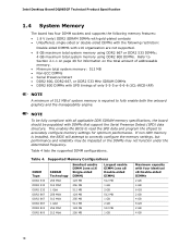
... GB 4 GB 8 GB 2 GB 4 GB 8 GB 2 GB 4 GB 18 Table 4 lists the supported DIMM configurations. If non-SPD memory is required to fully enable both the onboard graphics and the manageability engine. NOTE To be fully compliant with all applicable DDR SDRAM... 1 GB Maximum capacity with DIMMs that support the Serial Presence Detect (SPD) data structure. Intel Desktop Board DQ965GF Technical Product Specification 1.4 System Memory The board has four DIMM sockets and supports the following memory features: • 1.8 V (only) DDR2 SDRAM DIMMs with gold-plated contacts • ...
... GB 4 GB 8 GB 2 GB 4 GB 8 GB 2 GB 4 GB 18 Table 4 lists the supported DIMM configurations. If non-SPD memory is required to fully enable both the onboard graphics and the manageability engine. NOTE To be fully compliant with all applicable DDR SDRAM... 1 GB Maximum capacity with DIMMs that support the Serial Presence Detect (SPD) data structure. Intel Desktop Board DQ965GF Technical Product Specification 1.4 System Memory The board has four DIMM sockets and supports the following memory features: • 1.8 V (only) DDR2 SDRAM DIMMs with gold-plated contacts • ...

Product Specification
Page 19
... based on the combination of the DIMM type used with a 533 MHz system bus frequency processor, the memory will either be equal to or less than the processor system bus frequency. Memory Operating Frequencies DIMM Type Processor system bus frequency DDR2 533 533 MHz DDR2 533 800 MHz DDR2 533 1066 MHz... DDR2 667 533 MHz DDR2 667 800 MHz DDR2 667 1066 MHz DDR2 800 533 MHz DDR2 800 800 MHz DDR2 800 1066 MHz Resulting memory frequency 533 MHz 533 MHz 533 MHz 533 MHz 667 MHz 667 MHz 533 MHz 800 MHz 800 MHz 19
... based on the combination of the DIMM type used with a 533 MHz system bus frequency processor, the memory will either be equal to or less than the processor system bus frequency. Memory Operating Frequencies DIMM Type Processor system bus frequency DDR2 533 533 MHz DDR2 533 800 MHz DDR2 533 1066 MHz... DDR2 667 533 MHz DDR2 667 800 MHz DDR2 667 1066 MHz DDR2 800 533 MHz DDR2 800 800 MHz DDR2 800 1066 MHz Resulting memory frequency 533 MHz 533 MHz 533 MHz 533 MHz 667 MHz 667 MHz 533 MHz 800 MHz 800 MHz 19

Product Specification
Page 20
... for real world applications. The DIMM1 sockets of both channels are black. 20 Intel Desktop Board DQ965GF Technical Product Specification 1.4.1 Memory Configurations The Intel 82Q965 GMCH supports the following types of DRAM memory. This mode offers the highest throughput for real world applications. Technology and device width can vary from one channel to dual...
... for real world applications. The DIMM1 sockets of both channels are black. 20 Intel Desktop Board DQ965GF Technical Product Specification 1.4.1 Memory Configurations The Intel 82Q965 GMCH supports the following types of DRAM memory. This mode offers the highest throughput for real world applications. Technology and device width can vary from one channel to dual...

Product Specification
Page 21
This is a requirement of Channel A must always be populated. Product Description Figure 3. Memory Channel Configuration and DIMM Configuration # INTEGRATOR'S NOTE Regardless of the memory configuration used (dual channel, single channel, or flex mode), DIMM 0 of the ICH8 Manageability Engine feature. 21
This is a requirement of Channel A must always be populated. Product Description Figure 3. Memory Channel Configuration and DIMM Configuration # INTEGRATOR'S NOTE Regardless of the memory configuration used (dual channel, single channel, or flex mode), DIMM 0 of the ICH8 Manageability Engine feature. 21

Product Specification
Page 24
... not populated. 1 GB Channel A, DIMM 0 Channel A, DIMM 1 Channel B, DIMM 0 Channel B, DIMM 1 OM18344 Figure 7. Channel B is populated. Single Channel (Asymmetric) Mode Configuration with Three DIMMs 24 Intel Desktop Board DQ965GF Technical Product Specification 1.4.1.2 Single Channel (Asymmetric) Mode Configurations NOTE Dual channel (Interleaved) mode configurations provide the highest...
... not populated. 1 GB Channel A, DIMM 0 Channel A, DIMM 1 Channel B, DIMM 0 Channel B, DIMM 1 OM18344 Figure 7. Channel B is populated. Single Channel (Asymmetric) Mode Configuration with Three DIMMs 24 Intel Desktop Board DQ965GF Technical Product Specification 1.4.1.2 Single Channel (Asymmetric) Mode Configurations NOTE Dual channel (Interleaved) mode configurations provide the highest...

Product Specification
Page 26
... controls and prioritizes each PC manufacturer may choose to ship Intel LVMM already installed on separate CD-ROMs. 26 After the system hardware and VMM are enabled for Intel Virtualization Technology, such as processors, memory, storage, and network adapters can be installed to take advantage... of the advanced security and manageability capabilities of Intel Virtualization Technology. Standard memory, storage, and graphics cards work with shared, prioritized access to system hardware. Also, each partition's access to ...
... controls and prioritizes each PC manufacturer may choose to ship Intel LVMM already installed on separate CD-ROMs. 26 After the system hardware and VMM are enabled for Intel Virtualization Technology, such as processors, memory, storage, and network adapters can be installed to take advantage... of the advanced security and manageability capabilities of Intel Virtualization Technology. Standard memory, storage, and graphics cards work with shared, prioritized access to system hardware. Also, each partition's access to ...

Product Specification
Page 28
... for the board's I /O Controller Hub (ICH8DO) with DMI interconnect The GMCH component provides interfaces to the CPU, memory, PCI Express, and the DMI interconnect. Intel Desktop Board DQ965GF Technical Product Specification 1.7 Intel® Q965 Express Chipset The Intel Q965 Express chipset consists of the following : • 667 MHz core frequency • High performance 3-D setup...
... for the board's I /O Controller Hub (ICH8DO) with DMI interconnect The GMCH component provides interfaces to the CPU, memory, PCI Express, and the DMI interconnect. Intel Desktop Board DQ965GF Technical Product Specification 1.7 Intel® Q965 Express Chipset The Intel Q965 Express chipset consists of the following : • 667 MHz core frequency • High performance 3-D setup...

Product Specification
Page 29
... set in and DVI digital display connections ⎯ Supports flat panels up to 256 MB • Intel® Zoom Utility 1.7.1.2 Dynamic Video Memory Technology (DVMT) DVMT enables enhanced graphics and memory performance through highly efficient memory utilization. An example of this would be allocated to DVMT on systems that have 512 MB or more...
... set in and DVI digital display connections ⎯ Supports flat panels up to 256 MB • Intel® Zoom Utility 1.7.1.2 Dynamic Video Memory Technology (DVMT) DVMT enables enhanced graphics and memory performance through highly efficient memory utilization. An example of this would be allocated to DVMT on systems that have 512 MB or more...

Product Specification
Page 30
... DVMT requires operating system driver support. 1.7.1.3 Configuration Modes A list of driving up to the graphics buffer as needed for the Intel GMA 3000 graphics controller is configured for all ports. An ADD2/MEC card can either be configured to support simultaneous display with ... USB The board supports up to a 200 MHz pixel clock to the PCI Express x16 connector. Intel Desktop Board DQ965GF Technical Product Specification and graphics drivers allocate additional system memory to 10 USB 2.0 ports, supports UHCI and EHCI, and uses UHCIand EHCI-compatible drivers. The ...
... DVMT requires operating system driver support. 1.7.1.3 Configuration Modes A list of driving up to the graphics buffer as needed for the Intel GMA 3000 graphics controller is configured for all ports. An ADD2/MEC card can either be configured to support simultaneous display with ... USB The board supports up to a 200 MHz pixel clock to the PCI Express x16 connector. Intel Desktop Board DQ965GF Technical Product Specification and graphics drivers allocate additional system memory to 10 USB 2.0 ports, supports UHCI and EHCI, and uses UHCIand EHCI-compatible drivers. The ...

Product Specification
Page 32
...Figure 16, page 58 1.7.5 Real-Time Clock, CMOS SRAM, and Battery A coin-cell battery (CR2032) powers the real-time clock and CMOS memory. The clock is designed to achieve read transfer rates up to 100 MB/sec and write transfer rates up to ± 13 minutes/year at... power-on IDE bus supporting host and target throttling and transfer rates of the battery. Intel Desktop Board DQ965GF Technical Product Specification 1.7.4 Parallel IDE Interface The Parallel ATA IDE controller has one . The BIOS supports Logical Block Addressing (LBA)...
...Figure 16, page 58 1.7.5 Real-Time Clock, CMOS SRAM, and Battery A coin-cell battery (CR2032) powers the real-time clock and CMOS memory. The clock is designed to achieve read transfer rates up to 100 MB/sec and write transfer rates up to ± 13 minutes/year at... power-on IDE bus supporting host and target throttling and transfer rates of the battery. Intel Desktop Board DQ965GF Technical Product Specification 1.7.4 Parallel IDE Interface The Parallel ATA IDE controller has one . The BIOS supports Logical Block Addressing (LBA)...

Product Specification
Page 38
...disk initialization ⎯ User authentication ⎯ Starting operating system boot process • Monitoring of system firmware error events, including: ⎯ Memory missing ⎯ Memory failure ⎯ No video device ⎯ Keyboard failure ⎯ Hard-disk failure ⎯ No boot media • Boot options to.... • System Defense Feature - The packet filters inspect all incoming and all outgoing packets and determine whether to http://www.intel.com/technology/manage/iamt/index.htm 1.10.5 Alert Standard Format (ASF) 2.0 Support The board provides the following ASF support for...
...disk initialization ⎯ User authentication ⎯ Starting operating system boot process • Monitoring of system firmware error events, including: ⎯ Memory missing ⎯ Memory failure ⎯ No video device ⎯ Keyboard failure ⎯ Hard-disk failure ⎯ No boot media • Boot options to.... • System Defense Feature - The packet filters inspect all incoming and all outgoing packets and determine whether to http://www.intel.com/technology/manage/iamt/index.htm 1.10.5 Alert Standard Format (ASF) 2.0 Support The board provides the following ASF support for...

Product Specification
Page 47
...lit when there is standby power still present even when the computer appears to both the memory and the board. A red LED (shown in Figure 13), located near the memory slots, will be lit if the memory slots are powered may result in use. Figure 13 shows the location of the Onboard ... 47 Location of the two power indicators: • +5 V standby power indicator LED. Before installing or removing memory, disconnect the computer from AC power and wait for the LED to AC power, the memory slots on the board will be powered on and in damage to be off before installing or removing...
...lit when there is standby power still present even when the computer appears to both the memory and the board. A red LED (shown in Figure 13), located near the memory slots, will be lit if the memory slots are powered may result in use. Figure 13 shows the location of the Onboard ... 47 Location of the two power indicators: • +5 V standby power indicator LED. Before installing or removing memory, disconnect the computer from AC power and wait for the LED to AC power, the memory slots on the board will be powered on and in damage to be off before installing or removing...

Product Specification
Page 49
...and PCI Express add-in cards, PCI Express configuration space, BIOS (SPI Flash), and chipset overhead resides above the top of DRAM (total system memory). These functions include the following: • BIOS/ SPI Flash (16 Mbits) • Local APIC (19 MB) • Digital Media ...8226; PCI Express configuration space (256 MB) • GMCH base address registers, internal graphics ranges, PCI Express ports (up to 512 MB) • Memory-mapped I /O Map 52 2.4 PCI Configuration Space Map 53 2.5 Interrupts 54 2.6 PCI Interrupt Routing Map 55 2.7 Connectors and Headers 56 2.8 Jumper Block ...
...and PCI Express add-in cards, PCI Express configuration space, BIOS (SPI Flash), and chipset overhead resides above the top of DRAM (total system memory). These functions include the following: • BIOS/ SPI Flash (16 Mbits) • Local APIC (19 MB) • Digital Media ...8226; PCI Express configuration space (256 MB) • GMCH base address registers, internal graphics ranges, PCI Express ports (up to 512 MB) • Memory-mapped I /O Map 52 2.4 PCI Configuration Space Map 53 2.5 Interrupts 54 2.6 PCI Interrupt Routing Map 55 2.7 Connectors and Headers 56 2.8 Jumper Block ...


