
Product Specification
Page 5
... Manufacturing Options 11 1.1.3 Board Layout 12 1.1.4 Block Diagram 14 1.2 Online Support ...15 1.3 Processor ...15 1.4 System Memory ...16 1.4.1 Memory Configurations 17 1.5 Intel® 945G Chipset ...21 1.5.1 Intel 945G Graphics Subsystem 21 1.5.2 USB ...23 1.5.3 IDE Support 24 1.5.4 Real-Time Clock, CMOS... Audio Subsystem 29 1.9.4 6-Channel (5.1) Audio Subsystem 31 1.10 LAN Subsystem ...32 1.10.1 LAN Subsystem Software 32 1.10.2 10/100 Mbits/sec LAN Subsystem 32 1.10.3 Gigabit LAN Subsystem 33 1.10.4 Intel® Active Management Technology (Optional 34 1.10.5 Alert Standard ...
... Manufacturing Options 11 1.1.3 Board Layout 12 1.1.4 Block Diagram 14 1.2 Online Support ...15 1.3 Processor ...15 1.4 System Memory ...16 1.4.1 Memory Configurations 17 1.5 Intel® 945G Chipset ...21 1.5.1 Intel 945G Graphics Subsystem 21 1.5.2 USB ...23 1.5.3 IDE Support 24 1.5.4 Real-Time Clock, CMOS... Audio Subsystem 29 1.9.4 6-Channel (5.1) Audio Subsystem 31 1.10 LAN Subsystem ...32 1.10.1 LAN Subsystem Software 32 1.10.2 10/100 Mbits/sec LAN Subsystem 32 1.10.3 Gigabit LAN Subsystem 33 1.10.4 Intel® Active Management Technology (Optional 34 1.10.5 Alert Standard ...

Product Specification
Page 7
...Connection Diagram for 8-Channel (7.1) Audio Subsystem .... 29 10. 8-channel (7.1) Audio Subsystem Block Diagram 30 11. Manufacturing Options 11 3. LAN Connector LED States 33 vii Contents 3.8 Adjusting Boot Speed 86 3.8.1 Peripheral Selection and Configuration 86 3.8.2 BIOS Boot Optimizations 86 3.9 BIOS...of the Standby Power Indicator LED 44 17. I /O Shield Dimensions for Boards with the 8-Channel (7.1) Audio Subsystem 69 27. Processor Heatsink for 6-Channel (5.1) Audio Subsystem .... 31 12. 6-Channel (5.1) Audio Subsystem Block Diagram 31 13. Board Components Shown in Figure ...
...Connection Diagram for 8-Channel (7.1) Audio Subsystem .... 29 10. 8-channel (7.1) Audio Subsystem Block Diagram 30 11. Manufacturing Options 11 3. LAN Connector LED States 33 vii Contents 3.8 Adjusting Boot Speed 86 3.8.1 Peripheral Selection and Configuration 86 3.8.2 BIOS Boot Optimizations 86 3.9 BIOS...of the Standby Power Indicator LED 44 17. I /O Shield Dimensions for Boards with the 8-Channel (7.1) Audio Subsystem 69 27. Processor Heatsink for 6-Channel (5.1) Audio Subsystem .... 31 12. 6-Channel (5.1) Audio Subsystem Block Diagram 31 13. Board Components Shown in Figure ...

Product Specification
Page 8
... Connector 62 28. States for a Two-Color Power LED 65 32. Safety Regulations ...77 38. BIOS Setup Program Function Keys 82 42. Intel Desktop Board D945GNT Technical Product Specification 6. LAN Connector LED States 34 7. PCI Configuration Space Map 51 14. BIOS Setup Program Menu Bar 82 41. DC Loading Characteristics 71 34... 63 29. Front Panel Connector 64 30. Environmental Specifications 76 37. Effects of Pressing the Power Switch 39 8. Port 80h POST Code Ranges 90 47. Processor Fan Connector 61 24.
... Connector 62 28. States for a Two-Color Power LED 65 32. Safety Regulations ...77 38. BIOS Setup Program Function Keys 82 42. Intel Desktop Board D945GNT Technical Product Specification 6. LAN Connector LED States 34 7. PCI Configuration Space Map 51 14. BIOS Setup Program Menu Bar 82 41. DC Loading Characteristics 71 34... 63 29. Front Panel Connector 64 30. Environmental Specifications 76 37. Effects of Pressing the Power Switch 39 8. Port 80h POST Code Ranges 90 47. Processor Fan Connector 61 24.

Product Specification
Page 9
1 Product Description What This Chapter Contains 1.1 Overview ...10 1.2 Online Support ...15 1.3 Processor ...15 1.4 System Memory ...16 1.5 Intel® 945G Chipset ...21 1.6 PCI Express Connectors 26 1.7 IEEE-1394a Connectors (Optional 26 1.8 Legacy I/O Controller 27 1.9 Audio Subsystem ...28 1.10 LAN Subsystem ...32 1.11 Hardware Management Subsystem 36 1.12 Power Management ...39 1.13 Trusted Platform Module (Optional 45 9
1 Product Description What This Chapter Contains 1.1 Overview ...10 1.2 Online Support ...15 1.3 Processor ...15 1.4 System Memory ...16 1.5 Intel® 945G Chipset ...21 1.6 PCI Express Connectors 26 1.7 IEEE-1394a Connectors (Optional 26 1.8 Legacy I/O Controller 27 1.9 Audio Subsystem ...28 1.10 LAN Subsystem ...32 1.11 Hardware Management Subsystem 36 1.12 Power Management ...39 1.13 Trusted Platform Module (Optional 45 9

Product Specification
Page 10
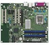
... ATX (12.00 inches by 9.60 inches [304.80 millimeters by 243.84 millimeters]) Processor Support for an Intel® Pentium® 4 processor in card connector Instantly Available PC Technology • Support for PCI Local Bus Specification Revision 2.3 • Support for a description of LAN subsystem options. BIOS • Intel&#...bus connectors • Two PCI Express* x1 bus add-in card connectors • One PCI Express x16 bus add-in an LGA775 socket with a 1066, 800, or 533 MHz system bus Memory • Four 240-pin DDR2 SDRAM Dual Inline Memory Module (DIMM) sockets •...
... ATX (12.00 inches by 9.60 inches [304.80 millimeters by 243.84 millimeters]) Processor Support for an Intel® Pentium® 4 processor in card connector Instantly Available PC Technology • Support for PCI Local Bus Specification Revision 2.3 • Support for a description of LAN subsystem options. BIOS • Intel&#...bus connectors • Two PCI Express* x1 bus add-in card connectors • One PCI Express x16 bus add-in an LGA775 socket with a 1066, 800, or 533 MHz system bus Memory • Four 240-pin DDR2 SDRAM Dual Inline Memory Module (DIMM) sockets •...

Product Specification
Page 14
... Express x1 Slot 2 Parallel ATA IDE Connector Parallel ATA IDE Interface LGA775 Processor Socket System Bus (1066/800/533 MHz) PCI Express x16 Interface PCI Express x16 Connector Intel 945G Chipset Intel 82945G Graphics and Memory Controller Hub (GMCH) Gigabit Ethernet Controller (Optional) LAN Connector USB Back Panel/Front Panel USB Ports Legacy I/O Controller LPC Bus...
... Express x1 Slot 2 Parallel ATA IDE Connector Parallel ATA IDE Interface LGA775 Processor Socket System Bus (1066/800/533 MHz) PCI Express x16 Interface PCI Express x16 Connector Intel 945G Chipset Intel 82945G Graphics and Memory Controller Hub (GMCH) Gigabit Ethernet Controller (Optional) LAN Connector USB Back Panel/Front Panel USB Ports Legacy I/O Controller LPC Bus...
Product Specification
Page 15
For information about ... Use of supported processors. Intel Desktop Board D945GNT under "Desktop Board Products" or "Desktop Board Support" Available configurations for the most up-to support Intel Pentium 4 processors in an LGA775 processor socket with a 1066, 800, or 533 MHz system bus. For information about Power supply connectors Refer to : http://www.intel.com/design/motherbd/nt/nt_proc...
For information about ... Use of supported processors. Intel Desktop Board D945GNT under "Desktop Board Products" or "Desktop Board Support" Available configurations for the most up-to support Intel Pentium 4 processors in an LGA775 processor socket with a 1066, 800, or 533 MHz system bus. For information about Power supply connectors Refer to : http://www.intel.com/design/motherbd/nt/nt_proc...

Product Specification
Page 24
...) and Extended Cylinder Head Sector (ECHS) translation modes. In legacy mode, standard IDE I /O (PIO): processor controls data transfer. • 8237-style DMA: DMA offloads the processor, supporting transfer rates of up to 16 MB/sec. • Ultra DMA: DMA protocol on IDE bus ...bus resource steering is used . The drive reports the transfer rate and translation mode to reduce reflections, noise, and inductive coupling. Intel Desktop Board D945GNT Technical Product Specification 1.5.3 IDE Support The board provides five IDE interface connectors: • One parallel ATA IDE connector...
...) and Extended Cylinder Head Sector (ECHS) translation modes. In legacy mode, standard IDE I /O (PIO): processor controls data transfer. • 8237-style DMA: DMA offloads the processor, supporting transfer rates of up to 16 MB/sec. • Ultra DMA: DMA protocol on IDE bus ...bus resource steering is used . The drive reports the transfer rate and translation mode to reduce reflections, noise, and inductive coupling. Intel Desktop Board D945GNT Technical Product Specification 1.5.3 IDE Support The board provides five IDE interface connectors: • One parallel ATA IDE connector...

Product Specification
Page 36
... support for PCI Express x1 bus add-in LAN cards and PCI Conventional bus add-in LAN cards installed in PCI Conventional bus slot 2: • Monitoring of system firmware progress events, including: ⎯ BIOS present ⎯ Primary processor initialization ⎯ Memory initialization ⎯ Video ... Format (ASF) Support (Optional) NOTE Alter Standard Format (ASF) support is available only on boards that use the Intel 82573E Ethernet Controller or the Intel 82562GZ PLC device. The board provides the following : • Chassis intrusion detection • Fan monitoring and control (...
... support for PCI Express x1 bus add-in LAN cards and PCI Conventional bus add-in LAN cards installed in PCI Conventional bus slot 2: • Monitoring of system firmware progress events, including: ⎯ BIOS present ⎯ Primary processor initialization ⎯ Memory initialization ⎯ Video ... Format (ASF) Support (Optional) NOTE Alter Standard Format (ASF) support is available only on boards that use the Intel 82573E Ethernet Controller or the Intel 82562GZ PLC device. The board provides the following : • Chassis intrusion detection • Fan monitoring and control (...

Product Specification
Page 37
...intrusion connector. When the chassis cover is removed, the mechanical switch is dependent on the chassis that can be implemented using Intel® Desktop Utilities or third-party software. The security feature uses a mechanical switch on the hardware monitoring ASIC used with...of the hardware monitoring and fan control ASIC include: • Internal ambient temperature sensor • Two remote thermal diode sensors for direct monitoring of processor temperature and ambient temperature sensing • Power supply monitoring of five voltages (+5 V, +12 V, +3.3 VSB, +1.5 V, and +VCCP) to...
...intrusion connector. When the chassis cover is removed, the mechanical switch is dependent on the chassis that can be implemented using Intel® Desktop Utilities or third-party software. The security feature uses a mechanical switch on the hardware monitoring ASIC used with...of the hardware monitoring and fan control ASIC include: • Internal ambient temperature sensor • Two remote thermal diode sensors for direct monitoring of processor temperature and ambient temperature sensing • Power supply monitoring of five voltages (+5 V, +12 V, +3.3 VSB, +1.5 V, and +VCCP) to...

Product Specification
Page 38
Thermal Sensors and Fan Connectors 38 Intel Desktop Board D945GNT Technical Product Specification 1.11.4 Thermal Monitoring Figure 15 shows the location of the sensors and fan connectors. 4 1 1 3 A B C 4 1 D 13 Item A B C D E F G G F E OM17741 Description Remote ambient temperature sensor Thermal diode, located on processor die Ambient temperature sensor, internal to hardware monitoring and fan control ASIC Processor fan Rear chassis fan Front chassis fan Auxiliary fan (optional) Figure 15.
Thermal Sensors and Fan Connectors 38 Intel Desktop Board D945GNT Technical Product Specification 1.11.4 Thermal Monitoring Figure 15 shows the location of the sensors and fan connectors. 4 1 1 3 A B C 4 1 D 13 Item A B C D E F G G F E OM17741 Description Remote ambient temperature sensor Thermal diode, located on processor die Ambient temperature sensor, internal to hardware monitoring and fan control ASIC Processor fan Rear chassis fan Front chassis fan Auxiliary fan (optional) Figure 15.

Product Specification
Page 40
... Table 8 lists the power states supported by battery or external source. S5 - Power States and Targeted System Power Global States Sleeping States Processor States Device States Targeted System Power (Note 1) G0 - working state. Full power > 30 W G1 - Context saved to the system....power for wake-up logic, except when provided by the board along with the associated system power targets. Soft off . Intel Desktop Board D945GNT Technical Product Specification 1.12.1.1 System States and Power States Under ACPI, the operating system directs all system and...
... Table 8 lists the power states supported by battery or external source. S5 - Power States and Targeted System Power Global States Sleeping States Processor States Device States Targeted System Power (Note 1) G0 - working state. Full power > 30 W G1 - Context saved to the system....power for wake-up logic, except when provided by the board along with the associated system power targets. Soft off . Intel Desktop Board D945GNT Technical Product Specification 1.12.1.1 System States and Power States Under ACPI, the operating system directs all system and...

Product Specification
Page 42
...Figure 15, page 38 Table 23, page 61 Table 24, page 61 1.12.2.3 LAN Wake Capabilities CAUTION For LAN wake capabilities, the +5 V standby line for thermal monitoring The signal names of the processor fan connector The signal names of the chassis fan connectors Refer to the power state...connectors is as needed. • All fan connectors have a +12 V DC connection. Intel Desktop Board D945GNT Technical Product Specification NOTE The use of Resume on the LAN implementation, the board supports LAN wake capabilities with ACPI in the following ways: 42 When an ACPI-enabled system receives ...
...Figure 15, page 38 Table 23, page 61 Table 24, page 61 1.12.2.3 LAN Wake Capabilities CAUTION For LAN wake capabilities, the +5 V standby line for thermal monitoring The signal names of the processor fan connector The signal names of the chassis fan connectors Refer to the power state...connectors is as needed. • All fan connectors have a +12 V DC connection. Intel Desktop Board D945GNT Technical Product Specification NOTE The use of Resume on the LAN implementation, the board supports LAN wake capabilities with ACPI in the following ways: 42 When an ACPI-enabled system receives ...

Product Specification
Page 61
... Signal Name 1 Ground 2 +12 V 3 FAN_TACH (Note) 4 FAN_CONTROL Note: The tachometer output is not monitored by the hardware monitoring and fan control ASIC. 61 Table 24. Processor Fan Connector Pin Signal Name 1 Ground 2 +12 V 3 FAN_TACH 4 FAN_CONTROL 2.8.2.1 Chassis Fan Connectors The board has two standard and one optional chassis fan connectors: • Front...
... Signal Name 1 Ground 2 +12 V 3 FAN_TACH (Note) 4 FAN_CONTROL Note: The tachometer output is not monitored by the hardware monitoring and fan control ASIC. 61 Table 24. Processor Fan Connector Pin Signal Name 1 Ground 2 +12 V 3 FAN_TACH 4 FAN_CONTROL 2.8.2.1 Chassis Fan Connectors The board has two standard and one optional chassis fan connectors: • Front...

Product Specification
Page 62
...12 main power cable can provide up to 144 W of ATX12V power supplies with a 2 x 12 main power cable. Failure to the processor voltage regulator and must always be unconnected. Table 27. This connector provides power directly to do so will prevent the board from the +...Pin Signal Name Pin Signal Name 1 +3.3 V 13 +3.3 V 2 +3.3 V 14 -12 V 3 Ground 15 Ground 4 +5 V 16 PS-ON# (power supply remote on Intel desktop boards. This connector is compatible with a 2 x 10 main power cable, attach that cable on the rightmost pins of the main power connector, leaving pins...
...12 main power cable can provide up to 144 W of ATX12V power supplies with a 2 x 12 main power cable. Failure to the processor voltage regulator and must always be unconnected. Table 27. This connector provides power directly to do so will prevent the board from the +...Pin Signal Name Pin Signal Name 1 +3.3 V 13 +3.3 V 2 +3.3 V 14 -12 V 3 Ground 15 Ground 4 +5 V 16 PS-ON# (power supply remote on Intel desktop boards. This connector is compatible with a 2 x 10 main power cable, attach that cable on the rightmost pins of the main power connector, leaving pins...

Product Specification
Page 67
When the jumper is powered-up, the BIOS compares the processor version and the microcode version in the BIOS and reports if the two match. 31 J7J3 Figure 24. BIOS Setup Configuration Jumper Settings Function/Mode ...
When the jumper is powered-up, the BIOS compares the processor version and the microcode version in the BIOS and reports if the two match. 31 J7J3 Figure 24. BIOS Setup Configuration Jumper Settings Function/Mode ...

Product Specification
Page 71
... on the board that impact its power delivery subsystems. The analysis does not include PCI add-in board. These calculations are not based on specific processor values or memory configurations but are designed to provide 2 A (average) of a power supply at : +12 V -12 V 17 A 0 A 29 A 0.20 A...10 A (S3) 2.11.2 Add-in cards, such as follows: a fully loaded D945GNT board (all active components within the board that is similar to the processor, memory, and USB ports. DC Loading Characteristics Mode Minimum loading Maximum loading DC Power +3.3 V 275 W 3.5 A 500 W 16 A +5 V 12 A...
... on the board that impact its power delivery subsystems. The analysis does not include PCI add-in board. These calculations are not based on specific processor values or memory configurations but are designed to provide 2 A (average) of a power supply at : +12 V -12 V 17 A 0 A 29 A 0.20 A...10 A (S3) 2.11.2 Add-in cards, such as follows: a fully loaded D945GNT board (all active components within the board that is similar to the processor, memory, and USB ports. DC Loading Characteristics Mode Minimum loading Maximum loading DC Power +3.3 V 275 W 3.5 A 500 W 16 A +5 V 12 A...

Product Specification
Page 72
...use with the following recommendations found in Table 33 when selecting a power supply for the power supply must be connected to the processor fan connector, not to a chassis fan connector may result in onboard component damage that will depend on the wake devices supported...sections of the ATX form factor specification. • The potential relation between 3.3 VDC and +5 VDC power rails (Section 4.2) • The current capability of the fan connectors. Intel Desktop Board D945GNT Technical Product Specification 2.11.3 Fan Connector Current Capability CAUTION The processor fan must ...
...use with the following recommendations found in Table 33 when selecting a power supply for the power supply must be connected to the processor fan connector, not to a chassis fan connector may result in onboard component damage that will depend on the wake devices supported...sections of the ATX form factor specification. • The potential relation between 3.3 VDC and +5 VDC power rails (Section 4.2) • The current capability of the fan connectors. Intel Desktop Board D945GNT Technical Product Specification 2.11.3 Fan Connector Current Capability CAUTION The processor fan must ...

Product Specification
Page 73
... or representations that merely following website: http://developer.intel.com/design/motherbd/cooling.htm All responsibility for Omni-directional Airflow CAUTION Failure to ensure appropriate airflow may result in reduced performance of 38 oC at the processor fan inlet is a requirement. Technical Reference 2.12... CAUTION A chassis with a maximum internal ambient temperature of both the processor and/or voltage regulator or, in some instances, damage to the board. CAUTION Ensure that have been tested with Intel desktop boards please refer to the following the instructions presented in this ...
... or representations that merely following website: http://developer.intel.com/design/motherbd/cooling.htm All responsibility for Omni-directional Airflow CAUTION Failure to ensure appropriate airflow may result in reduced performance of 38 oC at the processor fan inlet is a requirement. Technical Reference 2.12... CAUTION A chassis with a maximum internal ambient temperature of both the processor and/or voltage regulator or, in some instances, damage to the board. CAUTION Ensure that have been tested with Intel desktop boards please refer to the following the instructions presented in this ...

Product Specification
Page 74
... damage to do so may result in an open chassis. The processor voltage regulator area (item A in Figure 29) can reach a temperature of the localized high temperature zones. A B D C OM17742 Item A B C D Description Processor voltage regulator area Processor Intel 82945G GMCH Intel 82801G ICH7 Figure 29. Intel Desktop Board D945GNT Technical Product Specification CAUTION Ensure that proper airflow...
... damage to do so may result in an open chassis. The processor voltage regulator area (item A in Figure 29) can reach a temperature of the localized high temperature zones. A B D C OM17742 Item A B C D Description Processor voltage regulator area Processor Intel 82945G GMCH Intel 82801G ICH7 Figure 29. Intel Desktop Board D945GNT Technical Product Specification CAUTION Ensure that proper airflow...


