
Installation Guide
Page 1
Intel® Server Chassis SR2400 SCSI and SATA Backplane Kit Installation Guide Order Number: C83539-002
Intel® Server Chassis SR2400 SCSI and SATA Backplane Kit Installation Guide Order Number: C83539-002
Installation Guide
Page 2
...life sustaining applications or for such products, Intel assumes no liability whatsoever, and Intel disclaims any time, without notice. Intel is granted by estoppel or otherwise, to any intellectual property rights is a registered trademark of Intel products including liability or warranties relating to ...any express or implied warranty, relating to sale and/or use of Intel Corporation or its subsidiaries in connection with Intel® products. ii Intel® Server Chassis SR2400 SCSI and SATA Backplane Installation Instructions No license, express or implied, by this document...
...life sustaining applications or for such products, Intel assumes no liability whatsoever, and Intel disclaims any time, without notice. Intel is granted by estoppel or otherwise, to any intellectual property rights is a registered trademark of Intel products including liability or warranties relating to ...any express or implied warranty, relating to sale and/or use of Intel Corporation or its subsidiaries in connection with Intel® products. ii Intel® Server Chassis SR2400 SCSI and SATA Backplane Installation Instructions No license, express or implied, by this document...
Installation Guide
Page 4
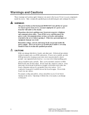
.... To remove power from server, you remove the Access Cover to ESD. WARNINGS The power button on your server when handling parts. iv Intel® Server Chassis SR2400 SCSI and SATA Backplane Installation Instructions There are present inside the server. Only a technically qualified person should be present on a grounded, static free surface.
.... To remove power from server, you remove the Access Cover to ESD. WARNINGS The power button on your server when handling parts. iv Intel® Server Chassis SR2400 SCSI and SATA Backplane Installation Instructions There are present inside the server. Only a technically qualified person should be present on a grounded, static free surface.
Installation Guide
Page 5
... into Drive Carrier 17 Figure 18. Installing Filler Panels 19 Contents v Contents About the SATA or SCSI Backplane Kit 1 Kit Contents...1 SCSI Backplane Kit ...1 SATA Backplane Kit ...3 Document Scope and Assumptions 4 Tools and Supplies Needed ...4 Intel® Server Chassis SR2400 SATA or SCSI Backplane Installation 5 Follow Steps in Quick Start User's Guide 5 Release Control...
... into Drive Carrier 17 Figure 18. Installing Filler Panels 19 Contents v Contents About the SATA or SCSI Backplane Kit 1 Kit Contents...1 SCSI Backplane Kit ...1 SATA Backplane Kit ...3 Document Scope and Assumptions 4 Tools and Supplies Needed ...4 Intel® Server Chassis SR2400 SATA or SCSI Backplane Installation 5 Follow Steps in Quick Start User's Guide 5 Release Control...

Installation Guide
Page 6
vi Intel® Server Chassis SR2400 SCSI and SATA Backplane Installation Instructions
vi Intel® Server Chassis SR2400 SCSI and SATA Backplane Installation Instructions
Installation Guide
Page 7
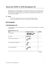
... SCSI Backplane can actually install depends on the server board capabilities and any SATA or SCSI add-in the Intel® Server Chassis SR2400. The SATA kit provides you with the ability to install up to six hot-swap SATA drives into your Server Chassis SR2400. Kit Contents SCSI Backplane Kit You should have... scale) Quantity 1 Flex cable 1 26-pin floppy drive data cable 1 44-pin CD-ROM drive data cable 1 50-pin front panel cable 1 continued About the SATA or SCSI Backplane Kit 1 The SCSI kit provides you can be installed in card that is installed.
... SCSI Backplane can actually install depends on the server board capabilities and any SATA or SCSI add-in the Intel® Server Chassis SR2400. The SATA kit provides you with the ability to install up to six hot-swap SATA drives into your Server Chassis SR2400. Kit Contents SCSI Backplane Kit You should have... scale) Quantity 1 Flex cable 1 26-pin floppy drive data cable 1 44-pin CD-ROM drive data cable 1 50-pin front panel cable 1 continued About the SATA or SCSI Backplane Kit 1 The SCSI kit provides you can be installed in card that is installed.
Installation Guide
Page 8
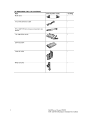
SCSI Backplane Parts List (continued) Item SCSI cable 10-pin fan distribution cable Picture (not to scale) 44-pin CD-ROM drive interposer board with two screws Hot-swap driver carrier Drive bay blank Quantity 1 1 1 5 1 Large air baffle 1 Small air baffle 1 2 Intel® Server Chassis SR2400 SCSI and SATA Backplane Installation Instructions
SCSI Backplane Parts List (continued) Item SCSI cable 10-pin fan distribution cable Picture (not to scale) 44-pin CD-ROM drive interposer board with two screws Hot-swap driver carrier Drive bay blank Quantity 1 1 1 5 1 Large air baffle 1 Small air baffle 1 2 Intel® Server Chassis SR2400 SCSI and SATA Backplane Installation Instructions
Installation Guide
Page 9
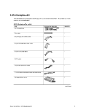
SATA Backplane Kit You should have received the following parts if you ordered the SATA Backplane Kit, order number A2400SATAKIT: SATA Backplane Parts List Item SATA backplane Picture (not to scale) Quantity 1 Flex cable 1 26-pin floppy drive data cable 1 44-pin CD-ROM drive data cable 1 50-pin front panel cable 1 SATA cable 5 10-pin fan distribution cable 1 CD-ROM drive interposer board with two screws 1 Hot-swap driver carrier 5 continued About the SATA or SCSI Backplane Kit 3
SATA Backplane Kit You should have received the following parts if you ordered the SATA Backplane Kit, order number A2400SATAKIT: SATA Backplane Parts List Item SATA backplane Picture (not to scale) Quantity 1 Flex cable 1 26-pin floppy drive data cable 1 44-pin CD-ROM drive data cable 1 50-pin front panel cable 1 SATA cable 5 10-pin fan distribution cable 1 CD-ROM drive interposer board with two screws 1 Hot-swap driver carrier 5 continued About the SATA or SCSI Backplane Kit 3
Installation Guide
Page 10
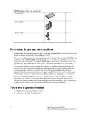
...with your installation. For boards other than the Server Board SE7520JR2 or Server Board SE7320VP2, refer to the documentation that came with other Intel® Server Boards as well. The User's Guide is currently operational, you through both the Quick Start User's Guide and this ...board to determine compatibility and cable routing. For the best results, read through installing the hot-swap SCSI or hot-swap SATA backplane into the Intel® Server Chassis SR2400. Because the Quick Start User's Guide used for the initial integration is used for instructions on removing...
...with your installation. For boards other than the Server Board SE7520JR2 or Server Board SE7320VP2, refer to the documentation that came with other Intel® Server Boards as well. The User's Guide is currently operational, you through both the Quick Start User's Guide and this ...board to determine compatibility and cable routing. For the best results, read through installing the hot-swap SCSI or hot-swap SATA backplane into the Intel® Server Chassis SR2400. Because the Quick Start User's Guide used for the initial integration is used for instructions on removing...
Installation Guide
Page 11
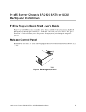
A TP00531 Figure 1. Intel® Server Chassis SR2400 SATA or SCSI Backplane Installation Follow Steps in Quick Start User's Guide Remove the CD-ROM tray if it is installed in the chassis and follow ... User's Guide will direct you to this guide at the appropriate point during the integration process. Releasing Control Panel Intel® Server Chassis SR2400 SATA or SCSI Backplane Installation 5 Release Control Panel Release lever (see letter "A" in the Intel® Server Chassis SR2400 Quick Start User's Guide that came with your server chassis.
A TP00531 Figure 1. Intel® Server Chassis SR2400 SATA or SCSI Backplane Installation Follow Steps in Quick Start User's Guide Remove the CD-ROM tray if it is installed in the chassis and follow ... User's Guide will direct you to this guide at the appropriate point during the integration process. Releasing Control Panel Intel® Server Chassis SR2400 SATA or SCSI Backplane Installation 5 Release Control Panel Release lever (see letter "A" in the Intel® Server Chassis SR2400 Quick Start User's Guide that came with your server chassis.
Installation Guide
Page 12
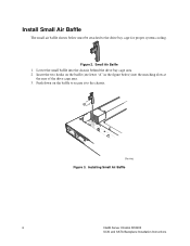
Lower the small baffle into the matching slots at the rear of the drive cage area. 3. Figure 3. Push down on the baffle (see letter "A" in the figure below must be attached to the chassis. Insert the two hooks on the baffle to secure it to the drive bay cage for proper system cooling. Installing Small Air Baffle 6 Intel® Server Chassis SR2400 SCSI and SATA Backplane Installation Instructions Small Air Baffle 1. Install Small Air Baffle The small air baffle shown below ) into the chassis behind the drive bay cage area. 2. Figure 2.
Lower the small baffle into the matching slots at the rear of the drive cage area. 3. Figure 3. Push down on the baffle (see letter "A" in the figure below must be attached to the chassis. Insert the two hooks on the baffle to secure it to the drive bay cage for proper system cooling. Installing Small Air Baffle 6 Intel® Server Chassis SR2400 SCSI and SATA Backplane Installation Instructions Small Air Baffle 1. Install Small Air Baffle The small air baffle shown below ) into the chassis behind the drive bay cage area. 2. Figure 2.
Installation Guide
Page 13
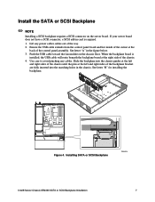
... the USB cable toward the fan module on the server board. See letter "B" for installing the backplane. Installing SATA or SCSI Backplane TP01074 Intel® Server Chassis SR2400 SATA or SCSI Backplane Installation 7 Install the SATA or SCSI Backplane ✏ NOTE Installing a SCSI backplane requires a SCSI connector on the chassis floor. If your server...
... the USB cable toward the fan module on the server board. See letter "B" for installing the backplane. Installing SATA or SCSI Backplane TP01074 Intel® Server Chassis SR2400 SATA or SCSI Backplane Installation 7 Install the SATA or SCSI Backplane ✏ NOTE Installing a SCSI backplane requires a SCSI connector on the chassis floor. If your server...
Installation Guide
Page 14
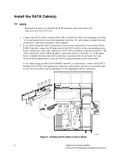
... backplane. The cable connected to SATA CH A should be connected to SATA 1. SATA SATA CH A SATA CH B SATA CH D CH C A A SATA CH E B SATA1 SATA0 C Figure 5. The cable connected to SATA CH B should be connected to SATA 0. Connect the SATA Cable(s) labeled SATA CH A and SATA CH B to Server Board TP01078 8 Intel® Server Chassis SR2400 SCSI and SATA Backplane Installation Instructions See letter "B" in...
... backplane. The cable connected to SATA CH A should be connected to SATA 1. SATA SATA CH A SATA CH B SATA CH D CH C A A SATA CH E B SATA1 SATA0 C Figure 5. The cable connected to SATA CH B should be connected to SATA 0. Connect the SATA Cable(s) labeled SATA CH A and SATA CH B to Server Board TP01078 8 Intel® Server Chassis SR2400 SCSI and SATA Backplane Installation Instructions See letter "B" in...
Installation Guide
Page 15
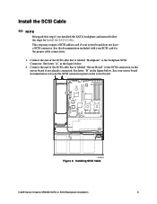
... on the server board if not already connected. See your SCSI card for Install the SATA Cable. Install the SCSI Cable ✏ NOTE Disregard this step if you installed the SATA backplane and instead follow the steps for the proper cable connections. 1. See letter "A"... in card if your server board does not have a SCSI connector. Installing SCSI Cable Intel® Server Chassis SR2400 SATA or SCSI Backplane Installation 9 See letter "B" in the figure below . 2. See the documentation included with your server board documentation ...
... on the server board if not already connected. See your SCSI card for Install the SATA Cable. Install the SCSI Cable ✏ NOTE Disregard this step if you installed the SATA backplane and instead follow the steps for the proper cable connections. 1. See letter "A"... in card if your server board does not have a SCSI connector. Installing SCSI Cable Intel® Server Chassis SR2400 SATA or SCSI Backplane Installation 9 See letter "B" in the figure below . 2. See the documentation included with your server board documentation ...
Installation Guide
Page 16
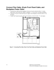
Connecting Flex Cable, 50-pin Front Panel Cable, and Backplane Power Cable 10 Intel® Server Chassis SR2400 SCSI and SATA Backplane Installation Instructions Attach the 2x3 power cable from the backplane to the server board as shown by letter "C" in the figure. 3. Figure 7. Attach the ...
Connecting Flex Cable, 50-pin Front Panel Cable, and Backplane Power Cable 10 Intel® Server Chassis SR2400 SCSI and SATA Backplane Installation Instructions Attach the 2x3 power cable from the backplane to the server board as shown by letter "C" in the figure. 3. Figure 7. Attach the ...
Installation Guide
Page 17
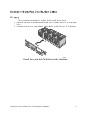
Attach the other end of the 10-pin fan distribution cable to the fan module. Connect 10-pin Fan Distribution Cable ✏ NOTE This step must be completed before installing the fan module into the chassis. 1. See letter "A" in the figure. Attach one end of the fan distribution cable to the backplane. B A TP01080 Figure 8. See letter "B" in the figure below. 2. Connecting 10-pin Fan Distribution Cable to Backplane Intel® Server Chassis SR2400 SATA or SCSI Backplane Installation 11
Attach the other end of the 10-pin fan distribution cable to the fan module. Connect 10-pin Fan Distribution Cable ✏ NOTE This step must be completed before installing the fan module into the chassis. 1. See letter "A" in the figure. Attach one end of the fan distribution cable to the backplane. B A TP01080 Figure 8. See letter "B" in the figure below. 2. Connecting 10-pin Fan Distribution Cable to Backplane Intel® Server Chassis SR2400 SATA or SCSI Backplane Installation 11
Installation Guide
Page 18
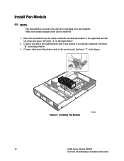
... of the ribbon cable to fan module if not already connected. See letter "B" in the figure below . 3. Installing Fan Module TP01081 12 Intel® Server Chassis SR2400 SCSI and SATA Backplane Installation Instructions Connect other end of the folded ribbon cable to the server board. Place the fan module over the chassis...
... of the ribbon cable to fan module if not already connected. See letter "B" in the figure below . 3. Installing Fan Module TP01081 12 Intel® Server Chassis SR2400 SCSI and SATA Backplane Installation Instructions Connect other end of the folded ribbon cable to the server board. Place the fan module over the chassis...
Installation Guide
Page 19
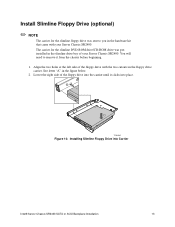
... Drive (optional) ✏ NOTE The carrier for the slimline DVD-ROM drive/CD-ROM drive was sent to remove it clicks into Carrier Intel® Server Chassis SR2400 SATA or SCSI Backplane Installation 13 A B TP01082 Figure 10. Align the two holes at the left side of the floppy drive into the carrier...
... Drive (optional) ✏ NOTE The carrier for the slimline DVD-ROM drive/CD-ROM drive was sent to remove it clicks into Carrier Intel® Server Chassis SR2400 SATA or SCSI Backplane Installation 13 A B TP01082 Figure 10. Align the two holes at the left side of the floppy drive into the carrier...
Installation Guide
Page 20
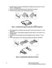
... cover to lock the cable into the connector. 5. Slide the floppy drive assembly into the chassis until it clicks into Chassis 14 Intel® Server Chassis SR2400 SCSI and SATA Backplane Installation Instructions See letter "B" in the figure below . 8. Installing Slimline Floppy Drive into place. See letter "A" in the figure. See letter...
... cover to lock the cable into the connector. 5. Slide the floppy drive assembly into the chassis until it clicks into Chassis 14 Intel® Server Chassis SR2400 SCSI and SATA Backplane Installation Instructions See letter "B" in the figure below . 8. Installing Slimline Floppy Drive into place. See letter "A" in the figure. See letter...
Installation Guide
Page 21
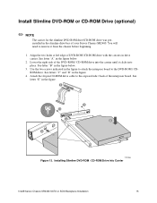
... DVD-ROM / CD-ROM Drive into place. See letter "B" in the figure to attach the interpose board to remove it clicks into Carrier Intel® Server Chassis SR2400 SATA or SCSI Backplane Installation 15 Align the two holes at left edge of the DVD-ROM / CD-ROM drive into the carrier until...
... DVD-ROM / CD-ROM Drive into place. See letter "B" in the figure to attach the interpose board to remove it clicks into Carrier Intel® Server Chassis SR2400 SATA or SCSI Backplane Installation 15 Align the two holes at left edge of the DVD-ROM / CD-ROM drive into the carrier until...