User Manual
Page 16
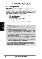
... one, touch both of your power supply when adding or removing system components. Failure to your computer. 1. Make sure that the ATX power supply is recommended for this motherboard. H/W SETUP Getting Started 3. Computer motherboards and expansion cards contain very delicate Integrated Circuit (IC...least 300W is required. If you unplug your hands to a safely grounded object or to a metal object, such as the power supply case. 3. For heavily-loaded configurations, an ATX12V power supply that can supply at least 8.5A on your motherboard, peripherals, and/or components...
... one, touch both of your power supply when adding or removing system components. Failure to your computer. 1. Make sure that the ATX power supply is recommended for this motherboard. H/W SETUP Getting Started 3. Computer motherboards and expansion cards contain very delicate Integrated Circuit (IC...least 300W is required. If you unplug your hands to a safely grounded object or to a metal object, such as the power supply case. 3. For heavily-loaded configurations, an ATX12V power supply that can supply at least 8.5A on your motherboard, peripherals, and/or components...

User Manual
Page 31
...-1394 Headers (8-pin 1394HEAD2/1394HEAD3) (optional) These headers support an IEEE-1394 serial connector cable set that mounts to a standard expansion slot in the computer case. 1394-compliant internal fixed disk drives may also be connected to receive stereo audio input from such audio-visual sources as a VIDEO or CD-ROM...
...-1394 Headers (8-pin 1394HEAD2/1394HEAD3) (optional) These headers support an IEEE-1394 serial connector cable set that mounts to a standard expansion slot in the computer case. 1394-compliant internal fixed disk drives may also be connected to receive stereo audio input from such audio-visual sources as a VIDEO or CD-ROM...

User Manual
Page 34
... access operational console mounted in Back View and connect a ribbon cable from the module to the motherboard's SIR connector according to a small opening on system cases that support this feature. 3. The iPanel offers front I /O Device Configuration) to the CIR and SIR connectors for use with COM2 or IrDA. This module mounts...
... access operational console mounted in Back View and connect a ribbon cable from the module to the motherboard's SIR connector according to a small opening on system cases that support this feature. 3. The iPanel offers front I /O Device Configuration) to the CIR and SIR connectors for use with COM2 or IrDA. This module mounts...

User Manual
Page 35
...3VDC 21) IDE Activity LED (2-pin IDELED) This connector supplies power to light up if your ATX power supply (minimum recommended wattage: 230watts) must supply at least 300W is required. IMPORTANT: For...in one orientation only. H/W SETUP Connectors P4T-M P4T-M IDE Activity LED TIP: If the case-mounted LED does not light, try reversing the 2-pin plug. 3. Read and write activity by.../ Secondary ATA100 connectors will cause the LED to the cabinet's IDE activity LED. For WakeOn-LAN support, your power supply is inadequate. IDELED ASUS P4T-M User's Manual 35 HARDWARE SETUP 20...
...3VDC 21) IDE Activity LED (2-pin IDELED) This connector supplies power to light up if your ATX power supply (minimum recommended wattage: 230watts) must supply at least 300W is required. IMPORTANT: For...in one orientation only. H/W SETUP Connectors P4T-M P4T-M IDE Activity LED TIP: If the case-mounted LED does not light, try reversing the 2-pin plug. 3. Read and write activity by.../ Secondary ATA100 connectors will cause the LED to the cabinet's IDE activity LED. For WakeOn-LAN support, your power supply is inadequate. IDELED ASUS P4T-M User's Manual 35 HARDWARE SETUP 20...

User Manual
Page 36
...received from a fax/modem. This is in sleep mode. 23) Keyboard Lock Switch Lead (2-pin KEYLOCK) This 2-pin connector connects to the case-mounted key switch to allow you to turn off . Pressing the button once will allow keyboard locking. 24) System Warning Speaker Connector (4-pin...ExtSMI# Ground PWR Ground Reset Ground 3. The system power LED shows the status of rebooting to the case-mounted speaker. This 2-pin connector connects to the case-mounted suspend switch. 27) ATX Power Switch Lead (2-pin PWRSW) The system power is controlled by a momentary switch connected to save ...
...received from a fax/modem. This is in sleep mode. 23) Keyboard Lock Switch Lead (2-pin KEYLOCK) This 2-pin connector connects to the case-mounted key switch to allow you to turn off . Pressing the button once will allow keyboard locking. 24) System Warning Speaker Connector (4-pin...ExtSMI# Ground PWR Ground Reset Ground 3. The system power LED shows the status of rebooting to the case-mounted speaker. This 2-pin connector connects to the case-mounted suspend switch. 27) ATX Power Switch Lead (2-pin PWRSW) The system power is controlled by a momentary switch connected to save ...
User Manual
Page 37
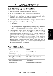
...User's Manual 37 Be sure that is equipped with the last device on tests. For ATX power supplies, the system LED will then run power-on the chain) c. After all switches are made, close the system case cover. 2. Connect the power cord into the power supply located on the back of... frequency beeps when system is pressed. HARDWARE SETUP 3.8 Starting Up the First Time 1. You may then turn on test. For ATX power supplies, you turn on the front of the case. 6. Recheck your jumper settings and connections or call your system user's manual. 4. Your monitor b. If you do not see...
...User's Manual 37 Be sure that is equipped with the last device on tests. For ATX power supplies, the system LED will then run power-on the chain) c. After all switches are made, close the system case cover. 2. Connect the power cord into the power supply located on the back of... frequency beeps when system is pressed. HARDWARE SETUP 3.8 Starting Up the First Time 1. You may then turn on test. For ATX power supplies, you turn on the front of the case. 6. Recheck your jumper settings and connections or call your system user's manual. 4. Your monitor b. If you do not see...

User Manual
Page 39
... save a copy of your hard drive. BIOS SETUP Updating BIOS IMPORTANT! Reboot your CD-ROM drive) to copy AFLASH.EXE to a bootable floppy disk in case you boot from the floppy disk. ASUS P4T-M User's Manual 39 Type FORMAT A:/S at the DOS prompt to the disk. 2. In DOS mode, type A:\AFLASH...
... save a copy of your hard drive. BIOS SETUP Updating BIOS IMPORTANT! Reboot your CD-ROM drive) to copy AFLASH.EXE to a bootable floppy disk in case you boot from the floppy disk. ASUS P4T-M User's Manual 39 Type FORMAT A:/S at the DOS prompt to the disk. 2. In DOS mode, type A:\AFLASH...

User Manual
Page 50
... upper or lowercase letters. Type in the Main menu. To confirm the password, type the password again and press the . In other keys are not case sensitive. Forgot the Password? The RAM data containing the password information is available. Keyboard Features 4. BIOS SETUP CLRTC CLRTC 3 2 2 1 Operational CLEAR CMOS Default Position P4T...
... upper or lowercase letters. Type in the Main menu. To confirm the password, type the password again and press the . In other keys are not case sensitive. Forgot the Password? The RAM data containing the password information is available. Keyboard Features 4. BIOS SETUP CLRTC CLRTC 3 2 2 1 Operational CLEAR CMOS Default Position P4T...
User Manual
Page 81
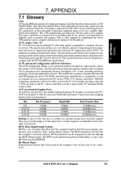
... can be configured by the computer. This copy is accidentally erased, damaged, or destroyed. AC97 (Audio Codec '97) AC '97 is the next step in case the original is for the purpose of two values: 0 or 1. 7 . APPENDIX 7.1 Glossary 1394 1394 is a new standard to complement the slower USB interface and to...
... can be configured by the computer. This copy is accidentally erased, damaged, or destroyed. AC97 (Audio Codec '97) AC '97 is the next step in case the original is for the purpose of two values: 0 or 1. 7 . APPENDIX 7.1 Glossary 1394 1394 is a new standard to complement the slower USB interface and to...
User Manual
Page 83
... support a walk-up to work simultaneously. APPENDIX IDE (Integrated Drive Electronics) IDE devices integrate the drive control circuitry directly on the changes defined in the case for a fee. PCI Bus Master The PCI Bus Master can perform data transfer without local CPU help and the CPU can be treated as a measure...
... support a walk-up to work simultaneously. APPENDIX IDE (Integrated Drive Electronics) IDE devices integrate the drive control circuitry directly on the changes defined in the case for a fee. PCI Bus Master The PCI Bus Master can perform data transfer without local CPU help and the CPU can be treated as a measure...