Specifications
Page 1
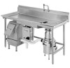
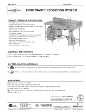
... A Sink Bowl Assembly with two water nozzles, includes removable splash baffle and stainless bowl cover ACCESSORIES Reel Rinse Spray Unit (Fisher #2980) Pre-Rinse Spray with wall bracket (Fisher #2010-WB) Pre-Rinse Spray with wall bracket - More information is a trademark and a service mark of Emerson Electric Co. The Emerson logo is available from Kochman Consultants, Ltd. PROJECT: ITEM NO.: FOOD WASTE...
... A Sink Bowl Assembly with two water nozzles, includes removable splash baffle and stainless bowl cover ACCESSORIES Reel Rinse Spray Unit (Fisher #2980) Pre-Rinse Spray with wall bracket (Fisher #2010-WB) Pre-Rinse Spray with wall bracket - More information is a trademark and a service mark of Emerson Electric Co. The Emerson logo is available from Kochman Consultants, Ltd. PROJECT: ITEM NO.: FOOD WASTE...

Specifications
Page 2
... of once daily. Control Panel • Install the WX-101A control panel per the Instruction, Care and Use manual. • When positioning disposer ensure that it is within 10' (3.1 m) of the disposer outlet flange. (See Figure 2) • The Waste Xpress should be cleaned with hot soapy water or in accordance to local, state and or national electric codes. • Position the control panel so...
... of once daily. Control Panel • Install the WX-101A control panel per the Instruction, Care and Use manual. • When positioning disposer ensure that it is within 10' (3.1 m) of the disposer outlet flange. (See Figure 2) • The Waste Xpress should be cleaned with hot soapy water or in accordance to local, state and or national electric codes. • Position the control panel so...

Specifications
Page 3
... installed in excess of serviceability. Trough Typical Installation Top View Water Nozzle Connect Cold Water Supply to end of trough and one water nozzle at end of trough. • For trough lengths greater than 7 GPM (26.5 LPM) must incorporate the second drain outlet from the disposer to the Waste Xpress use a maximum of (4) 90° bends (45° bends are recommended) with sink...
... installed in excess of serviceability. Trough Typical Installation Top View Water Nozzle Connect Cold Water Supply to end of trough and one water nozzle at end of trough. • For trough lengths greater than 7 GPM (26.5 LPM) must incorporate the second drain outlet from the disposer to the Waste Xpress use a maximum of (4) 90° bends (45° bends are recommended) with sink...

Owners Manual
Page 2
... 28 Motor Wiring Diagrams 30 3 Table of Contents Warranty ...4 Introduction/Typical Installation Introduction 4 Typical Installation 4 Waste Xpress Features 5 WX-101A Control Features/Mounting Control Center Introduction 6 Typical Installation 6 Installing Disposer 7 InSinkErator Mounting Assemblies Standard Mounting 8 Special Mounting 8 Installing Waste Xpress Waste Xpress Diagrams 9 Installing Waste Xpress 10 Electrical Connections 10 Plumbing Connections Waste Inlet Line 11 Reverse Auger Screen 11 Change Waste Inlet 11 Waste Outlet Line 12 Plumbing Connections 12 Water...
... 28 Motor Wiring Diagrams 30 3 Table of Contents Warranty ...4 Introduction/Typical Installation Introduction 4 Typical Installation 4 Waste Xpress Features 5 WX-101A Control Features/Mounting Control Center Introduction 6 Typical Installation 6 Installing Disposer 7 InSinkErator Mounting Assemblies Standard Mounting 8 Special Mounting 8 Installing Waste Xpress Waste Xpress Diagrams 9 Installing Waste Xpress 10 Electrical Connections 10 Plumbing Connections Waste Inlet Line 11 Reverse Auger Screen 11 Change Waste Inlet 11 Waste Outlet Line 12 Plumbing Connections 12 Water...

Owners Manual
Page 3
... water (sink or trough) • Hot water (Waste Xpress) Sink Bowl Syphon Breaker Cold Water Solenoid Hot Water Solenoid Disposer Figure 1. InSinkErator and/or InSinkErator Factory Authorized Service Centers do not make original installations. TYPICAL INSTALLATION A typical Waste Xpress installation incorporates the following connections (see Figure 1 for typical installation). Important - Typical Installation WX-101A Controller Flow Control Valve Shut Off Valve 4 Waste Xpress The kitchen waste is ground through the disposer then transferred to the Waste...
... water (sink or trough) • Hot water (Waste Xpress) Sink Bowl Syphon Breaker Cold Water Solenoid Hot Water Solenoid Disposer Figure 1. InSinkErator and/or InSinkErator Factory Authorized Service Centers do not make original installations. TYPICAL INSTALLATION A typical Waste Xpress installation incorporates the following connections (see Figure 1 for typical installation). Important - Typical Installation WX-101A Controller Flow Control Valve Shut Off Valve 4 Waste Xpress The kitchen waste is ground through the disposer then transferred to the Waste...

Owners Manual
Page 5
... switch on a 24 V solid state control circuit. It interlocks with all local codes. • Turn off electrical supply to junction box. MOUNTING THE CONTROL CENTER Use the flanges at Waste Xpress, control center & disposer electrical supply source. • Use only NEMA 4 watertight electrical connectors when connecting to Waste Xpress, control center & disposer before it . Model Part No. WX TIMER HOT WATER SPRAY ADJUSTABLE Factory set for 2 minutes off , the water continues...
... switch on a 24 V solid state control circuit. It interlocks with all local codes. • Turn off electrical supply to junction box. MOUNTING THE CONTROL CENTER Use the flanges at Waste Xpress, control center & disposer electrical supply source. • Use only NEMA 4 watertight electrical connectors when connecting to Waste Xpress, control center & disposer before it . Model Part No. WX TIMER HOT WATER SPRAY ADJUSTABLE Factory set for 2 minutes off , the water continues...

Owners Manual
Page 7
...ange up out of non-InSinkErator style sinks. (Mounting instructions are included, adjust the legs to support the disposer. #6 Collar Adaptor (1) Mounting Flange (2) Mounting Gasket (3) Flat Gasket Disposer Body Flange 1/4" Screw #7 Collar Adaptor (1) Mounting Flange (2) Mounting Gasket Disposer Body Flange 1/4" Screw Figure 6. #6 Mounting Assembly Figure 7. #7 or Sink Bowl Mounting Assembly SPECIAL INSINKERATOR MOUNTING ASSEMBLIES When installing an InSinkErator Foodservice disposer to engage the two protruding screws in the mounting gasket (2) onto the connection lip. From the bottom...
...ange up out of non-InSinkErator style sinks. (Mounting instructions are included, adjust the legs to support the disposer. #6 Collar Adaptor (1) Mounting Flange (2) Mounting Gasket (3) Flat Gasket Disposer Body Flange 1/4" Screw #7 Collar Adaptor (1) Mounting Flange (2) Mounting Gasket Disposer Body Flange 1/4" Screw Figure 6. #6 Mounting Assembly Figure 7. #7 or Sink Bowl Mounting Assembly SPECIAL INSINKERATOR MOUNTING ASSEMBLIES When installing an InSinkErator Foodservice disposer to engage the two protruding screws in the mounting gasket (2) onto the connection lip. From the bottom...

Owners Manual
Page 9
... turning the legs in or out with panels removed. • All components (disposer, WX, control center and solenoids) must be carefully and permanently grounded. • A properly fused disconnect must be installed at Waste Xpress, control center & disposer electrical supply source. • Use only NEMA 4 watertight electrical connectors when connecting to junction box. WX Auger Motor 1 Phase WX Auger Motor 3 Phase WX Magnetic Interlock Cold Water Solenoid (Disposer) Hot Water Solenoid (WX Spray) Disposer WX...
... turning the legs in or out with panels removed. • All components (disposer, WX, control center and solenoids) must be carefully and permanently grounded. • A properly fused disconnect must be installed at Waste Xpress, control center & disposer electrical supply source. • Use only NEMA 4 watertight electrical connectors when connecting to junction box. WX Auger Motor 1 Phase WX Auger Motor 3 Phase WX Magnetic Interlock Cold Water Solenoid (Disposer) Hot Water Solenoid (WX Spray) Disposer WX...

Owners Manual
Page 10
... appropriate screws. D. Connect the disposer outlet to the bottom portion (see Figure 18). Remove auger from screen by lifting up and then out (see Figure 15). E. Figure 17. Install gaskets, cap and inlet fitting on reverse side and secure with as few as possible (not to top portion with all local codes. Figure 15. 1. B. Remove four nuts and washers...
... appropriate screws. D. Connect the disposer outlet to the bottom portion (see Figure 18). Remove auger from screen by lifting up and then out (see Figure 15). E. Figure 17. Install gaskets, cap and inlet fitting on reverse side and secure with as few as possible (not to top portion with all local codes. Figure 15. 1. B. Remove four nuts and washers...

Owners Manual
Page 11
.... Use 1/2" compression fitting to connect hot water to disposer, bowl, or trough. Connect hot water only to Waste Xpress for ease of the arrows marked on each valve body. Fresh water connection to the Waste Xpress must be switched to the other side, complete the following: • Remove the four screws holding the cap and gasket in malfunction. Typical Installation Diagram 12 Waste Xpress If the water outlet connection on...
.... Use 1/2" compression fitting to connect hot water to disposer, bowl, or trough. Connect hot water only to Waste Xpress for ease of the arrows marked on each valve body. Fresh water connection to the Waste Xpress must be switched to the other side, complete the following: • Remove the four screws holding the cap and gasket in malfunction. Typical Installation Diagram 12 Waste Xpress If the water outlet connection on...

Owners Manual
Page 12
... and electrical codes. • All components (disposer, WX, control center and solenoids) must be carefully and permanently grounded. • A properly fused disconnect must be installed at the electrical supply source for correct voltage using NEMA 4 water-tight electrical connections. A wiring diagram is to be used on it. PROPERTY DAMAGE • Ensure that power is to ensure that control center voltage and phase match the disposer motor and electrical...
... and electrical codes. • All components (disposer, WX, control center and solenoids) must be carefully and permanently grounded. • A properly fused disconnect must be installed at the electrical supply source for correct voltage using NEMA 4 water-tight electrical connections. A wiring diagram is to be used on it. PROPERTY DAMAGE • Ensure that power is to ensure that control center voltage and phase match the disposer motor and electrical...

Owners Manual
Page 13
... chute should be wired correctly. Ensure plumbing and electrical connections are installed and engaged correctly prior to work on and 2 minutes off automatically if interlock switch is functioning properly. Turn on incoming cold water supply to disposer and hot water supply to disposer and Waste Xpress. Push start button on the WX-101A control panel will result in position. 5. Turn on incoming power to the Waste Xpress. 3. On...
... chute should be wired correctly. Ensure plumbing and electrical connections are installed and engaged correctly prior to work on and 2 minutes off automatically if interlock switch is functioning properly. Turn on incoming cold water supply to disposer and hot water supply to disposer and Waste Xpress. Push start button on the WX-101A control panel will result in position. 5. Turn on incoming power to the Waste Xpress. 3. On...

Owners Manual
Page 14
... disposer TO STOP 1. Locate the water shutoff delay at the factory. NOTE: This feature is free of food waste. Push start button. This post-flush clears the drain lines of foreign objects. 2. To activate the automatic timed system shutoff, disconnect the electric power to match the filled in the WX-101A (see Figure 23). The dip switches should not be turned...
... disposer TO STOP 1. Locate the water shutoff delay at the factory. NOTE: This feature is free of food waste. Push start button. This post-flush clears the drain lines of foreign objects. 2. To activate the automatic timed system shutoff, disconnect the electric power to match the filled in the WX-101A (see Figure 23). The dip switches should not be turned...

Owners Manual
Page 17
... interlock switch. Troubleshooting performed by a qualified service person. Note: you may need to the Waste Xpress, disposer and/or Control Center. and water operate properly. • The disposer jammed. SOLUTION • Turn on electrical supply. • Replace fuse or reset circuit breaker. • Reinstall chute to prime itself. • Waste will not start or stops • The disposer overload while grinding, but the Waste Xpress...
... interlock switch. Troubleshooting performed by a qualified service person. Note: you may need to the Waste Xpress, disposer and/or Control Center. and water operate properly. • The disposer jammed. SOLUTION • Turn on electrical supply. • Replace fuse or reset circuit breaker. • Reinstall chute to prime itself. • Waste will not start or stops • The disposer overload while grinding, but the Waste Xpress...

Owners Manual
Page 18
...; Disposer is overloaded with food waste. Water flows continuously before controls are turned on the valve pointing in correct direction. • Reinstall the water solenoid valve with excessive amounts of food waste. 19 SOLUTION • Reinstall discharge chute to ensure proper fit. • Replace fuse or reset circuit breaker. • Push start button on control center. • Clear drain. • Add second waste outlet drain connect...
...; Disposer is overloaded with food waste. Water flows continuously before controls are turned on the valve pointing in correct direction. • Reinstall the water solenoid valve with excessive amounts of food waste. 19 SOLUTION • Reinstall discharge chute to ensure proper fit. • Replace fuse or reset circuit breaker. • Push start button on control center. • Clear drain. • Add second waste outlet drain connect...

Owners Manual
Page 19
... the manual setting is desired, change indicated in the feature section. • Disposer is jammed. • Press stop button and follow directions for but water flows. • Overload protector on front of garbage and water. 20 Disposer motor stops while grinding • Control center wired for dejamming in the direction of disposer electrical cover. Locate red reset button on the disposer may have tripped. • Press stop button. installed backward. • Water fl...
... the manual setting is desired, change indicated in the feature section. • Disposer is jammed. • Press stop button and follow directions for but water flows. • Overload protector on front of garbage and water. 20 Disposer motor stops while grinding • Control center wired for dejamming in the direction of disposer electrical cover. Locate red reset button on the disposer may have tripped. • Press stop button. installed backward. • Water fl...

Owners Manual
Page 20
...; Power to dipswitch setting instructions. operating properly. • Check interlock switch #3 and #95 connections on WX-101A #7 to WX. • Call service Hot Water Spray is cold. Water Shuts off when unit shuts off • Waste Xpress Interlock not of the nearest approved service agency. 21 Auger reverses direction on each re-start . • Waste Xpress unit auger motor has been wired into disposer motor circuit. • Incorrect wiring...
...; Power to dipswitch setting instructions. operating properly. • Check interlock switch #3 and #95 connections on WX-101A #7 to WX. • Call service Hot Water Spray is cold. Water Shuts off when unit shuts off • Waste Xpress Interlock not of the nearest approved service agency. 21 Auger reverses direction on each re-start . • Waste Xpress unit auger motor has been wired into disposer motor circuit. • Incorrect wiring...

Owners Manual
Page 21
... nearest InSinkErator Authorized Service Agency or to local electrical codes. • All components (disposer, WX, control center and solenoids) must be installed at the electrical supply source for voltage and phase specification. • The disposer motor wiring connection is off. • Installation must be carefully and permanently grounded. • A properly fused disconnect must conform to reach Technical Support. 22 Waste Xpress 120V, 1Phase System Wiring Diagram ELECTRICAL...
... nearest InSinkErator Authorized Service Agency or to local electrical codes. • All components (disposer, WX, control center and solenoids) must be installed at the electrical supply source for voltage and phase specification. • The disposer motor wiring connection is off. • Installation must be carefully and permanently grounded. • A properly fused disconnect must conform to reach Technical Support. 22 Waste Xpress 120V, 1Phase System Wiring Diagram ELECTRICAL...

Owners Manual
Page 23
... match the disposer motor and electrical supply. PROPERTY DAMAGE • Ensure that power is shown in the disposer terminal box. 208/230 V 1-phase Call Toll Free 1-800-845-8345 for the nearest InSinkErator Authorized Service Agency or to reach Technical Support. 24 Waste Xpress 208/230V, 1Phase System Wiring Diagram ELECTRICAL SHOCK • Turn off . • Installation must conform to local electrical codes. • All components (disposer, WX, control...
... match the disposer motor and electrical supply. PROPERTY DAMAGE • Ensure that power is shown in the disposer terminal box. 208/230 V 1-phase Call Toll Free 1-800-845-8345 for the nearest InSinkErator Authorized Service Agency or to reach Technical Support. 24 Waste Xpress 208/230V, 1Phase System Wiring Diagram ELECTRICAL SHOCK • Turn off . • Installation must conform to local electrical codes. • All components (disposer, WX, control...

Owners Manual
Page 25
... disposer motor and electrical supply. PROPERTY DAMAGE • Ensure that power is shown in the disposer terminal box. 120 V 210-8p/h2a3s0eV 1/32-ptoha2sHeP Call Toll Free 1-800-845-8345 for the nearest InSinkErator Authorized Service Agency or to reach Technical Support. 26 Waste Xpress 208/230V, 3Phase System Wiring Diagram ELECTRICAL SHOCK • Turn off . • Installation must conform to local electrical codes. • All components (disposer, WX...
... disposer motor and electrical supply. PROPERTY DAMAGE • Ensure that power is shown in the disposer terminal box. 120 V 210-8p/h2a3s0eV 1/32-ptoha2sHeP Call Toll Free 1-800-845-8345 for the nearest InSinkErator Authorized Service Agency or to reach Technical Support. 26 Waste Xpress 208/230V, 3Phase System Wiring Diagram ELECTRICAL SHOCK • Turn off . • Installation must conform to local electrical codes. • All components (disposer, WX...


