

English Manual
Page 6
...cleared area and remove the packing materials. Assembly will take time. Do not tighten the Nylon Locknuts yet. 1 31 1 27 27 29 2 27 29 31 2. Press a 60mm Square Outer Cap (27) onto the end of the Right and Left Bases (1, 3). Assembly Make Things Easier for assembly: • Two adjustable wrenches &#... holes on page 5. Attach the Rear Uprights (8) to the Center Base (2) using two M10 x 78mm Bolts (31) and two M10 Nylon Locknuts (29). Press 60mm Square Outer Caps (27) onto the ends of the Weight Guide Base (4). Do not tighten the Nylon Locknuts yet. Do not tighten the Nylon...
...cleared area and remove the packing materials. Assembly will take time. Do not tighten the Nylon Locknuts yet. 1 31 1 27 27 29 2 27 29 31 2. Press a 60mm Square Outer Cap (27) onto the end of the Right and Left Bases (1, 3). Assembly Make Things Easier for assembly: • Two adjustable wrenches &#... holes on page 5. Attach the Rear Uprights (8) to the Center Base (2) using two M10 x 78mm Bolts (31) and two M10 Nylon Locknuts (29). Press 60mm Square Outer Caps (27) onto the ends of the Weight Guide Base (4). Do not tighten the Nylon Locknuts yet. Do not tighten the Nylon...
English Manual
Page 8
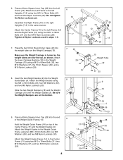
...(36), and two M8 Nylon Locknuts (30). 6. Do not tighten the Nylon Locknuts yet. Press the two 51mm Round Inner Caps (42) into the end of the Center Frame (11) and the Weight Guides... (9). Press a 60mm Square Inner Cap (28) into the weight tubes on top of the Weight Guide Frame ...Frame (11) to the left Uprights (7, 8) using four M10 x 78mm Bolts (31) and four M10 Nylon Locknuts (29). Press a 60mm Square Inner Cap (28) into the Weight Guide Base (4). Insert the two Weight Guides (9) into the Left Frame (...
...(36), and two M8 Nylon Locknuts (30). 6. Do not tighten the Nylon Locknuts yet. Press the two 51mm Round Inner Caps (42) into the end of the Center Frame (11) and the Weight Guides... (9). Press a 60mm Square Inner Cap (28) into the weight tubes on top of the Weight Guide Frame ...Frame (11) to the left Uprights (7, 8) using four M10 x 78mm Bolts (31) and four M10 Nylon Locknuts (29). Press a 60mm Square Inner Cap (28) into the Weight Guide Base (4). Insert the two Weight Guides (9) into the Left Frame (...

English Manual
Page 11
... Plates (63), four M10 x 72mm Bolts (34), and four M10 Nylon Locknuts (29). Attach the Bench Leg (48) to the floor. Press two 25mm x 38mm Inner Caps into each Backrest Tube (71). Make sure that the warning decal is in the position shown. Attach the Stabilizer so ... 25mm x 38mm Inner Caps (72) into the Backrest Adjustment Bracket (79). Lubricate a M10 x 192mm Bolt (66). 17. Press a 50mm Square Outer Cap (65) onto each end of the Bench Base (53). Note: Tighten all the M10 Nylon Locknuts (29) used in the position shown. Be sure the welded nut is in steps...
... Plates (63), four M10 x 72mm Bolts (34), and four M10 Nylon Locknuts (29). Attach the Bench Leg (48) to the floor. Press two 25mm x 38mm Inner Caps into each Backrest Tube (71). Make sure that the warning decal is in the position shown. Attach the Stabilizer so ... 25mm x 38mm Inner Caps (72) into the Backrest Adjustment Bracket (79). Lubricate a M10 x 192mm Bolt (66). 17. Press a 50mm Square Outer Cap (65) onto each end of the Bench Base (53). Note: Tighten all the M10 Nylon Locknuts (29) used in the position shown. Be sure the welded nut is in steps...

English Manual
Page 12
... (52) with the Bolt and a M10 Nylon Locknut (29). Attach the Seat Mounting Bracket (67) to the bracket on the Bench Frame (52) so that the Seat Adjustment Bracket (80) fits over tighten the Nylon Locknut; Note: Do not over tighten the Nylon Locknut; the Backrest Tubes must pivot easily. 21 Lubricate... 37 66 71 Welded Tube 52 37 29 22. Press the 20mm x 40mm Inner Cap (77) into the open end of the...
... (52) with the Bolt and a M10 Nylon Locknut (29). Attach the Seat Mounting Bracket (67) to the bracket on the Bench Frame (52) so that the Seat Adjustment Bracket (80) fits over tighten the Nylon Locknut; Note: Do not over tighten the Nylon Locknut; the Backrest Tubes must pivot easily. 21 Lubricate... 37 66 71 Welded Tube 52 37 29 22. Press the 20mm x 40mm Inner Cap (77) into the open end of the...

English Manual
Page 13
... (49) with the Small Adjustment Knob (81). 26 49 Insert a 45mm Square Inner Cap (26) into the weight tube on the 70 Adjustable Bench Leg (49). Press a 25mm Angled Outer Cap (82) onto the other end of the Leg Lever (62). Slide a Foam Pad (69) onto each 69 side of the Adjustable... Bench Leg (49). 81 48 26. Insert a 25mm Round Inner Cap (83) into the top of the Pad Tubes. 61 Insert a Pad Tube (61) through...
... (49) with the Small Adjustment Knob (81). 26 49 Insert a 45mm Square Inner Cap (26) into the weight tube on the 70 Adjustable Bench Leg (49). Press a 25mm Angled Outer Cap (82) onto the other end of the Leg Lever (62). Slide a Foam Pad (69) onto each 69 side of the Adjustable... Bench Leg (49). 81 48 26. Insert a 25mm Round Inner Cap (83) into the top of the Pad Tubes. 61 Insert a Pad Tube (61) through...