
Instruction Manual
Page 1
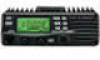
INSTRUCTION MANUAL VHF FM TRANSCEIVER iV8000 This device complies with Part 15 of the FCC rules. Operation is subject to the following two conditions: (1) This device may not cause harmful interference, and (2) this device must accept any interference received, including interference that may cause undesired operation.
INSTRUCTION MANUAL VHF FM TRANSCEIVER iV8000 This device complies with Part 15 of the FCC rules. Operation is subject to the following two conditions: (1) This device may not cause harmful interference, and (2) this device must accept any interference received, including interference that may cause undesired operation.

Instruction Manual
Page 2
...10061; Optional DTMF decoder i IMPORTANT READ ALL INSTRUCTIONS carefully and completely before using the transceiver. No risk of your time to thank you for making your IC-V8000 your IC-V8000. FOREWORD Thank you with years of trouble-free operation. NOTE Recommended for purchasing this ... you for optimum use. many, France, Spain, Russia and/or other countries. The IC-V8000 VHF FM TRANSCEIVER is designed and built with Icom's philosophy of "technology first." Icom, Icom Inc. Many hours of research and development went into the design of your radio of...
...10061; Optional DTMF decoder i IMPORTANT READ ALL INSTRUCTIONS carefully and completely before using the transceiver. No risk of your time to thank you for making your IC-V8000 your IC-V8000. FOREWORD Thank you with years of trouble-free operation. NOTE Recommended for purchasing this ... you for optimum use. many, France, Spain, Russia and/or other countries. The IC-V8000 VHF FM TRANSCEIVER is designed and built with Icom's philosophy of "technology first." Icom, Icom Inc. Many hours of research and development went into the design of your radio of...
Instruction Manual
Page 3
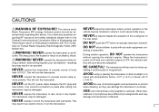
... or in an electric shock or ruin the transceiver. NEVER connect the transceiver to an AC outlet. This will ruin the transceiver. NEVER operate or touch the transceiver with FCC Guidelines for long periods. BE CAREFUL! USE Icom microphones only (supplied or optional). Other man- NEVER expose the transceiver to play with temperatures below -10°...
... or in an electric shock or ruin the transceiver. NEVER connect the transceiver to an AC outlet. This will ruin the transceiver. NEVER operate or touch the transceiver with FCC Guidelines for long periods. BE CAREFUL! USE Icom microphones only (supplied or optional). Other man- NEVER expose the transceiver to play with temperatures below -10°...

Instruction Manual
Page 6
QUICK REFERENCE GUIDE Installation D Location Select a location which can support the weight of the function display. AVOID placing the transceiver in the diagram below. Installation location D Using the mounting bracket ➀ Drill 4 holes where the mounting bracket is to be hindered or where it . approx..... ➁ Insert the supplied screws, nuts and washers through the mounting bracket and tighten. ➂ Adjust the angle for the clearest view of the transceiver and does not interfere with driving in any way. Nut Spring washer Flat washer When using nuts; DO NOT place the...
QUICK REFERENCE GUIDE Installation D Location Select a location which can support the weight of the function display. AVOID placing the transceiver in the diagram below. Installation location D Using the mounting bracket ➀ Drill 4 holes where the mounting bracket is to be hindered or where it . approx..... ➁ Insert the supplied screws, nuts and washers through the mounting bracket and tighten. ➂ Adjust the angle for the clearest view of the transceiver and does not interfere with driving in any way. Nut Spring washer Flat washer When using nuts; DO NOT place the...
Instruction Manual
Page 7
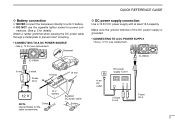
QUICK REFERENCE GUIDE D Battery connection NEVER connect the transceiver directly to an AC outlet DC power supply 13.8 V −⊕ − black ⊕ red Fuses 20 A II DO NOT use the cigarette lighter socket ... DC power cable through a metal plate to prevent short circuiting. • CONNECTING TO A DC POWER SOURCE • See p. 72 for the cable connections. IC-V8000 to a 24 V battery. Grommet IC-V8000 ⊕ red − black Fuses 20 A _ black + red 12 V 12 V battery NOTE: Crimp Use terminals for fuse replacement. Supplied DC power cable Solder...
QUICK REFERENCE GUIDE D Battery connection NEVER connect the transceiver directly to an AC outlet DC power supply 13.8 V −⊕ − black ⊕ red Fuses 20 A II DO NOT use the cigarette lighter socket ... DC power cable through a metal plate to prevent short circuiting. • CONNECTING TO A DC POWER SOURCE • See p. 72 for the cable connections. IC-V8000 to a 24 V battery. Grommet IC-V8000 ⊕ red − black Fuses 20 A _ black + red 12 V 12 V battery NOTE: Crimp Use terminals for fuse replacement. Supplied DC power cable Solder...

Instruction Manual
Page 8
... the connector body on the front panel of the IC-V8000. A nonradial antenna should be supplied with your local dealer for more information and recommendations. Strip the cable jacket and soft solder. Check with some versions of the transceiver. *HM-133V; Roof-mount antenna (Drill a ... Soft solder 1-2 mm q Slide the coupling ring down. QUICK REFERENCE GUIDE D Antenna installation • Antenna location To obtain maximum performance from the transceiver, select a high-quality antenna and mount it . r Screw the coupling ring onto the connector body. (10 mm ≈ 3⁄8 in...
... the connector body on the front panel of the IC-V8000. A nonradial antenna should be supplied with your local dealer for more information and recommendations. Strip the cable jacket and soft solder. Check with some versions of the transceiver. *HM-133V; Roof-mount antenna (Drill a ... Soft solder 1-2 mm q Slide the coupling ring down. QUICK REFERENCE GUIDE D Antenna installation • Antenna location To obtain maximum performance from the transceiver, select a high-quality antenna and mount it . r Screw the coupling ring onto the connector body. (10 mm ≈ 3⁄8 in...

Instruction Manual
Page 9
...pointers have purchased a brand new transceiver, some settings may want to operate. Turning ON the transceiver Before powering up your first "On The Air" an enjoyable experience. 1. Although you may be changed from factory default. 2. Now you want to make your IC-V8000, you have been helpful. Pages...-133V keypad. [EXAMPLE]: Setting frequency to reset the CPU. QUICK REFERENCE GUIDE Your first contact Now that you have your IC-V8000 installed in your car or shack, you through a few basic operation steps to make sure the audio volume and squelch level controls...
...pointers have purchased a brand new transceiver, some settings may want to operate. Turning ON the transceiver Before powering up your first "On The Air" an enjoyable experience. 1. Although you may be changed from factory default. 2. Now you want to make your IC-V8000, you have been helpful. Pages...-133V keypad. [EXAMPLE]: Setting frequency to reset the CPU. QUICK REFERENCE GUIDE Your first contact Now that you have your IC-V8000 installed in your car or shack, you through a few basic operation steps to make sure the audio volume and squelch level controls...

Instruction Manual
Page 16
... rotates while receiving depending on the setting in a vehicle. NOTE: DO NOT use a cigarette lighter socket as a power source when operating in set mode and transceiver's temperature. (p. 61) r ANTENNA CONNECTOR [ANT] Connects a 50 Ω antenna with the supplied DC power cable.
... rotates while receiving depending on the setting in a vehicle. NOTE: DO NOT use a cigarette lighter socket as a power source when operating in set mode and transceiver's temperature. (p. 61) r ANTENNA CONNECTOR [ANT] Connects a 50 Ω antenna with the supplied DC power cable.

Instruction Manual
Page 17
... receiving while the one -touch PTT function is in use . (p. 16) e UP/DOWN SWITCHES [Y]/[Z] ➥ Push either switch for 1 sec. to select call your desired transceiver conditions. !0 BANK/OPTION SWITCH [BANK/OPTION] ➥ Push to select memory mode. (p. 24) ➥ Push for 1 sec. to start scanning. (p. 38) r ACTIVITY INDICATOR 1 ➥ Lights...
... receiving while the one -touch PTT function is in use . (p. 16) e UP/DOWN SWITCHES [Y]/[Z] ➥ Push either switch for 1 sec. to select call your desired transceiver conditions. !0 BANK/OPTION SWITCH [BANK/OPTION] ➥ Push to select memory mode. (p. 24) ➥ Push for 1 sec. to start scanning. (p. 38) r ACTIVITY INDICATOR 1 ➥ Lights...

Instruction Manual
Page 20
... select VFO mode. The display shows that in 1 MHz (10 MHz for 1 sec. to select VFO mode. Push [PWR] for 1 sec. D VFO mode selection The transceiver has 2 basic operating modes: VFO mode and memory mode. ➥ Push [V/MHz(SCAN)] to turn power ON and OFF. cel it. 2 SETTING A FREQUENCY Preparation D Turning...
... select VFO mode. The display shows that in 1 MHz (10 MHz for 1 sec. to select VFO mode. Push [PWR] for 1 sec. D VFO mode selection The transceiver has 2 basic operating modes: VFO mode and memory mode. ➥ Push [V/MHz(SCAN)] to turn power ON and OFF. cel it. 2 SETTING A FREQUENCY Preparation D Turning...
Instruction Manual
Page 23
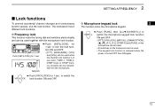
... together with the microphone lock function. SETTING A FREQUENCY 2 Lock functions To prevent accidental channel changes and unnecessary function access, use . The transceiver has 2 different lock functions. Push [SET(LOCK)] for 1 sec. Appears ➥ Push [SET(LOCK)] for 1 sec. D Microphone.../LOCK], [MR/CALL], [BANK/OPTION], [Y], [Z], [F-1], [F-2], [DTMF-S] and [FUNC] on the microphone can be used. • All switches on the transceiver can be transmitted from the microphone. ➥ Push [VFO/LOCK] for 1 sec. to turn the lock function ON and OFF. • [PTT], ...
... together with the microphone lock function. SETTING A FREQUENCY 2 Lock functions To prevent accidental channel changes and unnecessary function access, use . The transceiver has 2 different lock functions. Push [SET(LOCK)] for 1 sec. Appears ➥ Push [SET(LOCK)] for 1 sec. D Microphone.../LOCK], [MR/CALL], [BANK/OPTION], [Y], [Z], [F-1], [F-2], [DTMF-S] and [FUNC] on the microphone can be used. • All switches on the transceiver can be transmitted from the microphone. ➥ Push [VFO/LOCK] for 1 sec. to turn the lock function ON and OFF. • [PTT], ...

Instruction Manual
Page 24
... OPERATION Receiving q Push [PWR] for the received signal. r Set the operating frequency. (pgs. 9, 10) t When receiving a signal on the set frequency, squelch opens and the transceiver emits audio. • "BUSY" appears and the S/RF indicator shows the relative signal strength for 1 sec. to open the squelch. • "BUSY" blinks. • Push...
... OPERATION Receiving q Push [PWR] for the received signal. r Set the operating frequency. (pgs. 9, 10) t When receiving a signal on the set frequency, squelch opens and the transceiver emits audio. • "BUSY" appears and the S/RF indicator shows the relative signal strength for 1 sec. to open the squelch. • "BUSY" blinks. • Push...

Instruction Manual
Page 25
... o'clock and fully clockwise position. • When setting the squelch from the microphone, a level greater than '19' activates the squelch attenuator. Appears Squelch attenuator The transceiver has an RF attenuator related to cancel the function. Approx. 10 dB attenuation is open. BASIC OPERATION 3 Audio mute function This function temporarily mutes the...
... o'clock and fully clockwise position. • When setting the squelch from the microphone, a level greater than '19' activates the squelch attenuator. Appears Squelch attenuator The transceiver has an RF attenuator related to cancel the function. Approx. 10 dB attenuation is open. BASIC OPERATION 3 Audio mute function This function temporarily mutes the...

Instruction Manual
Page 26
... return to select output power. ➥ Push [HIGH 4(DTCS)] for 75 W transmission): The IC-V8000 is connected, or when the transceiver temperature becomes extremely high, the transceiver reduces transmit output power to 25 W (approx.) automatically. 15 Selecting output power The transceiver has 4* output power levels to select the output power. 3 BASIC OPERATION Transmitting CAUTION: Transmitting...
... return to select output power. ➥ Push [HIGH 4(DTCS)] for 75 W transmission): The IC-V8000 is connected, or when the transceiver temperature becomes extremely high, the transceiver reduces transmit output power to 25 W (approx.) automatically. 15 Selecting output power The transceiver has 4* output power levels to select the output power. 3 BASIC OPERATION Transmitting CAUTION: Transmitting...

Instruction Manual
Page 27
c Push [FUNC] then [PRIO 3(PTT-M)] to turn the one -touch PTT function ON. • The activity indicator lights green. Using this function, the transceiver has a time-out timer. z Push [FUNC] then [PRIO 3(PTT-M)] to turn the PTT-M one -touch PTT function OFF. • The activity indicator goes out. See p. ...
c Push [FUNC] then [PRIO 3(PTT-M)] to turn the one -touch PTT function ON. • The activity indicator lights green. Using this function, the transceiver has a time-out timer. z Push [FUNC] then [PRIO 3(PTT-M)] to turn the PTT-M one -touch PTT function OFF. • The activity indicator goes out. See p. ...
Instruction Manual
Page 31
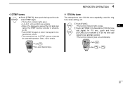
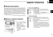
... 100 MHz digit, cancel the DTMF memory encoder in advance. (p. 46) • Push [DTMF-S] again to return the keypad to normal function control. • The transceiver has 10 DTMF memory channels for details. See p. 45 for autopatch operation. z Push [FUNC]. D 1750 Hz tone The microphone has 1750 Hz tone capability, used...
... 100 MHz digit, cancel the DTMF memory encoder in advance. (p. 46) • Push [DTMF-S] again to return the keypad to normal function control. • The transceiver has 10 DTMF memory channels for details. See p. 45 for autopatch operation. z Push [FUNC]. D 1750 Hz tone The microphone has 1750 Hz tone capability, used...

Instruction Manual
Page 32
... [PWR] to other stations by the offset frequency. Repeater lockout USING INITIAL SET MODE This function helps prevent interference to exit initial set mode. The transceiver has two inhibiting conditions, repeater and busy. Repeater lockout function is received. v Push [CLR A(MW)] to set mode. c Push [Y] or [Z] to exit set the desired...
... [PWR] to other stations by the offset frequency. Repeater lockout USING INITIAL SET MODE This function helps prevent interference to exit initial set mode. The transceiver has two inhibiting conditions, repeater and busy. Repeater lockout function is received. v Push [CLR A(MW)] to set mode. c Push [Y] or [Z] to exit set the desired...
Instruction Manual
Page 35
... memory mode. MR/CALL x Push [ENT C(T-OFF)] to select and set the desired memory channel. 4 Y/Z • Pushing [Y]/[Z] for numeral input. 5 MEMORY OPERATION General description The transceiver has 207 memory channels including 6 scan edge memory channels (3 pairs), and 1 call channel.
... memory mode. MR/CALL x Push [ENT C(T-OFF)] to select and set the desired memory channel. 4 Y/Z • Pushing [Y]/[Z] for numeral input. 5 MEMORY OPERATION General description The transceiver has 207 memory channels including 6 scan edge memory channels (3 pairs), and 1 call channel.

Instruction Manual
Page 54
...WATCH Priority watch types Priority watch starts. The watch types to the selected scan resume condition. MEMORY CHANNEL WATCH While operating on a memory channel. The transceiver has 3 priority watch resumes according to suit your needs. See previous page for signals on a VFO frequency every 5 sec. frequency 50 msec. while...operating on a VFO frequency, priority watch checks for a signal on each memory channel in sequence. • The memory skip function is activated, the transceiver automatically selects the tone squelch function when priority watch checks for details.
...WATCH Priority watch types Priority watch starts. The watch types to the selected scan resume condition. MEMORY CHANNEL WATCH While operating on a memory channel. The transceiver has 3 priority watch resumes according to suit your needs. See previous page for signals on a VFO frequency every 5 sec. frequency 50 msec. while...operating on a VFO frequency, priority watch checks for a signal on each memory channel in sequence. • The memory skip function is activated, the transceiver automatically selects the tone squelch function when priority watch checks for details.

Instruction Manual
Page 55
e Push [M/CALL(PRIO)] for 1 sec. to start the watch. • The transceiver checks the memory or call channel every 5 sec. • The watch : Select the desired memory channel. PRIORITY WATCH 8 z Select VFO mode; For memory scan watch ... memory channel watch resumes according to the selected scan re- dition. (p. 42) • While the watch is paused). 44 to start the watch. • The transceiver checks the memory or call channel every 5 sec. • The watch : Push [MR/CALL], then push [SCAN 2] to start the memory scan. c Push [PRIO 3(PTT...
e Push [M/CALL(PRIO)] for 1 sec. to start the watch. • The transceiver checks the memory or call channel every 5 sec. • The watch : Select the desired memory channel. PRIORITY WATCH 8 z Select VFO mode; For memory scan watch ... memory channel watch resumes according to the selected scan re- dition. (p. 42) • While the watch is paused). 44 to start the watch. • The transceiver checks the memory or call channel every 5 sec. • The watch : Push [MR/CALL], then push [SCAN 2] to start the memory scan. c Push [PRIO 3(PTT...