Instruction Manual
Page 1
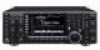
HF/50 MHz TRANSCEIVER i7700 Instruction Manual A-6612H-1EX-q Printed in Japan © 2008 Icom Inc.
HF/50 MHz TRANSCEIVER i7700 Instruction Manual A-6612H-1EX-q Printed in Japan © 2008 Icom Inc.
Instruction Manual
Page 2
... manual contains impor- These limits are registered trademarks of Icom Incorporated (Japan) in the United States, the United Kingdom, Germany, France, Spain, Russia and/or other countries. An LCD filter has been added to operate the transceiver. We hope you for Electromagnetic interference (EMI) and ...if not installed and used in Baudot RTTY and PSK31 modulator/demodulator and direct PC keyboard connection capability for the IC-7700. TRADEMARKS Icom, Icom Inc. In some instances, the LCD may cause harmful interference to part 15 of the FCC Rules. FOREWORD Thank you ...
... manual contains impor- These limits are registered trademarks of Icom Incorporated (Japan) in the United States, the United Kingdom, Germany, France, Spain, Russia and/or other countries. An LCD filter has been added to operate the transceiver. We hope you for Electromagnetic interference (EMI) and ...if not installed and used in Baudot RTTY and PSK31 modulator/demodulator and direct PC keyboard connection capability for the IC-7700. TRADEMARKS Icom, Icom Inc. In some instances, the LCD may cause harmful interference to part 15 of the FCC Rules. FOREWORD Thank you ...
Instruction Manual
Page 3
...amplifier will not use a linear amplifier, set - The transceiver weighs approx. 22.5 kg (50 lb). AVOID using or storing the transceiver in areas with a headset or other ob- This may scratch the surface of time. Use Icom microphones only (supplied or optional). Other manufacturers' microphones have... connectors on a slanted surface or vibrated place). R CAUTION! This may result in a secure place to the IC-7700 may damage the transceiver or microphone. Always have different pin assignments, and connection to avoid inadvertent use chemical agents such as output power,...
...amplifier will not use a linear amplifier, set - The transceiver weighs approx. 22.5 kg (50 lb). AVOID using or storing the transceiver in areas with a headset or other ob- This may scratch the surface of time. Use Icom microphones only (supplied or optional). Other manufacturers' microphones have... connectors on a slanted surface or vibrated place). R CAUTION! This may result in a secure place to the IC-7700 may damage the transceiver or microphone. Always have different pin assignments, and connection to avoid inadvertent use chemical agents such as output power,...
Instruction Manual
Page 9
...-24 ■ Deleting a file 12-25 ■ Unmounting USB-Memory 12-25 ■ Formatting the USB-Memory 12-26 Section 13 MAINTENANCE ■ Troubleshooting 13-2 D Transceiver power 13-2 D Transmit and receive 13-2 D Scanning 13-3 D Display 13-3 D Format USB-Memory 13-3 ■ Main dial brake adjustment 13-3 ■ SWR reading 13-4 ■...
...-24 ■ Deleting a file 12-25 ■ Unmounting USB-Memory 12-25 ■ Formatting the USB-Memory 12-26 Section 13 MAINTENANCE ■ Troubleshooting 13-2 D Transceiver power 13-2 D Transmit and receive 13-2 D Scanning 13-3 D Display 13-3 D Format USB-Memory 13-3 ■ Main dial brake adjustment 13-3 ■ SWR reading 13-4 ■...
Instruction Manual
Page 12
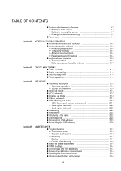
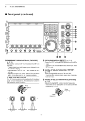
...internal speaker or connected external speaker does not function. The internal power supply switch is located on the rear panel. (p. 3-2) ➥ Push to turn the transceiver power ON. • The [POWER] indicator above this switch lights green when powered ON. ➥ Push and hold for 1 sec. • The ... lights green when the timer is in keyer set mode when pushed and held for 1 sec. to turn the transceiver power OFF. • The [POWER] indicator lights orange when the transceiver is OFF when the internal power supply is open. See [CW KEY] on p. 1-12. • Keyer polarity...
...internal speaker or connected external speaker does not function. The internal power supply switch is located on the rear panel. (p. 3-2) ➥ Push to turn the transceiver power ON. • The [POWER] indicator above this switch lights green when powered ON. ➥ Push and hold for 1 sec. • The ... lights green when the timer is in keyer set mode when pushed and held for 1 sec. to turn the transceiver power OFF. • The [POWER] indicator lights orange when the transceiver is OFF when the internal power supply is open. See [CW KEY] on p. 1-12. • Keyer polarity...
Instruction Manual
Page 14
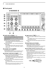
...the transceiver reads or writes to the memory data. • Unmount operation should be performed before removing the USB-Memory* (p.12-25). ➥ Connects a PC keyboard for RTTY and PSK31 operations. • USB keyboards* are supported. *: USB-Memory or USB keyboard is not supplied by Icom.... Insert USB-Memory* for maximum readability. • To use this control, push NB . 1 PANEL DESCRIPTION ■ Front panel (continued) !7 !8 POWER HF/50MHz TRANSCEIVER i7700 TRANSMIT TUNER VOX BK-IN MONITOR MIC RF PWR KEY SPEED DELAY TIMER PHONES AGC SQL NR NB ELEC-KEY MIC AGC VR NR...
...the transceiver reads or writes to the memory data. • Unmount operation should be performed before removing the USB-Memory* (p.12-25). ➥ Connects a PC keyboard for RTTY and PSK31 operations. • USB keyboards* are supported. *: USB-Memory or USB keyboard is not supplied by Icom.... Insert USB-Memory* for maximum readability. • To use this control, push NB . 1 PANEL DESCRIPTION ■ Front panel (continued) !7 !8 POWER HF/50MHz TRANSCEIVER i7700 TRANSMIT TUNER VOX BK-IN MONITOR MIC RF PWR KEY SPEED DELAY TIMER PHONES AGC SQL NR NB ELEC-KEY MIC AGC VR NR...
Instruction Manual
Page 20
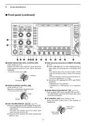
PBT2 PBT1 - + &1 &0 ^9 ^2 PBT CLEAR SWITCH PBT-CLR (p. 5-12) Clears the PBT settings when pushed and held for the PBT function. This transceiver uses the DSP circuit for 1 sec. • The [PBT-CLR] indicator above this switch lights when PBT is in use . ^4 DIGITAL RF SELECTOR CONTROL [DIGI-...
PBT2 PBT1 - + &1 &0 ^9 ^2 PBT CLEAR SWITCH PBT-CLR (p. 5-12) Clears the PBT settings when pushed and held for the PBT function. This transceiver uses the DSP circuit for 1 sec. • The [PBT-CLR] indicator above this switch lights when PBT is in use . ^4 DIGITAL RF SELECTOR CONTROL [DIGI-...
Instruction Manual
Page 22
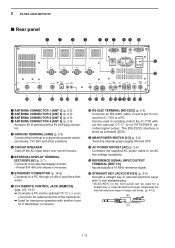
... key or external electronic keyer with 1⁄4 inch standard plug. • [ELEC-KEY] on the front panel can be used for transceive operation with a PL-259 plug connector. The [RS-232C] interface is necessary. o CI-V REMOTE CONTROL JACK [REMOTE] (pgs. ...CONNECTOR 4 [ANT 4] (p. 2-5) Accept a 50 Ω antenna with another Icom CI-V transceiver or receiver. !0 RS-232C TERMINAL [RS-232C] (p. 2-6) Connects an RS-232C cable, D-sub 9-pin to connect the IC-7700 to remotely control the IC-7700 without the optional CT-17, or for RTTY/PSK31 decoded signal output. Deactivate the...
... key or external electronic keyer with 1⁄4 inch standard plug. • [ELEC-KEY] on the front panel can be used for transceive operation with a PL-259 plug connector. The [RS-232C] interface is necessary. o CI-V REMOTE CONTROL JACK [REMOTE] (pgs. ...CONNECTOR 4 [ANT 4] (p. 2-5) Accept a 50 Ω antenna with another Icom CI-V transceiver or receiver. !0 RS-232C TERMINAL [RS-232C] (p. 2-6) Connects an RS-232C cable, D-sub 9-pin to connect the IC-7700 to remotely control the IC-7700 without the optional CT-17, or for RTTY/PSK31 decoded signal output. Deactivate the...
Instruction Manual
Page 23
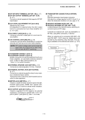
...1 [ACC 1] @1 ACCESSORY SOCKET 2 [ACC 2] Enable connection of a non-Icom linear amplifier. !9 T/R CONTROL JACK [RELAY] (p. 2-8) Connects to ground when transmitting to control an external unit, such as a non-Icom linear amplifier. Connects an external unit, such as a linear amplifier, an automatic antenna... (p. 2-7) Connects external equipment that supports S/P DIF input/output. !7 ALC LEVEL ADJUSTMENT POT [ALC ADJ] Adjusts the ALC levels. Transceiver mute control line (both transmit and receive) is also supported. @4 METER JACK [METER] (p. 2-7) Outputs a signal showing received signal...
...1 [ACC 1] @1 ACCESSORY SOCKET 2 [ACC 2] Enable connection of a non-Icom linear amplifier. !9 T/R CONTROL JACK [RELAY] (p. 2-8) Connects to ground when transmitting to control an external unit, such as a non-Icom linear amplifier. Connects an external unit, such as a linear amplifier, an automatic antenna... (p. 2-7) Connects external equipment that supports S/P DIF input/output. !7 ALC LEVEL ADJUSTMENT POT [ALC ADJ] Adjusts the ALC levels. Transceiver mute control line (both transmit and receive) is also supported. @4 METER JACK [METER] (p. 2-7) Outputs a signal showing received signal...
Instruction Manual
Page 27
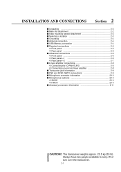
... D Front panel 2-6 D Rear panel-1 2-6 D Rear panel-2 2-7 ■ Linear amplifier connections 2-8 D Connecting the IC-PW1/EURO 2-8 D Connecting a non-Icom linear amplifier 2-8 ■ Transverter jack information 2-9 ■ FSK and AFSK (SSTV) connections 2-9 ■ Microphone connector ...information 2-10 ■ Microphones (options 2-10 D SM-20 2-10 D HM-36 2-10 ■ Accessory connector information 2-11 CAUTION!: The transceiver...
... D Front panel 2-6 D Rear panel-1 2-6 D Rear panel-2 2-7 ■ Linear amplifier connections 2-8 D Connecting the IC-PW1/EURO 2-8 D Connecting a non-Icom linear amplifier 2-8 ■ Transverter jack information 2-9 ■ FSK and AFSK (SSTV) connections 2-9 ■ Microphone connector ...information 2-10 ■ Microphones (options 2-10 D SM-20 2-10 D HM-36 2-10 ■ Accessory connector information 2-11 CAUTION!: The transceiver...
Instruction Manual
Page 28
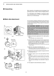
... the screw until the screw extends into the shaft hole out slightly using supplied hexagonal wrench as the main dial, when carrying or lifting the transceiver. e Attach the main dial as desired. r Tighten the screw using supplied hexagonal wrench (2 mm) (Fig. 2). • Be careful that the screw...with the IC-7700, see 'Supplied accessories' on the main dial by little. • Be careful to the delivering carrier or dealer. iii of the dial knob. • Never install the rubber cover on p. Front side Side view Fig. 4 2-2 The main dial is shipped unattached to the transceiver to ...
... the screw until the screw extends into the shaft hole out slightly using supplied hexagonal wrench as the main dial, when carrying or lifting the transceiver. e Attach the main dial as desired. r Tighten the screw using supplied hexagonal wrench (2 mm) (Fig. 2). • Be careful that the screw...with the IC-7700, see 'Supplied accessories' on the main dial by little. • Be careful to the delivering carrier or dealer. iii of the dial knob. • Never install the rubber cover on p. Front side Side view Fig. 4 2-2 The main dial is shipped unattached to the transceiver to ...
Instruction Manual
Page 29
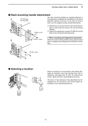
...M4 × 15 mm Attach the rack mounting handles using original screws when re-packing and shipping the transceiver at any time. The base of the transceiver has adjustable feet for the transceiver that allows adequate air circulation, free from extreme heat, cold, or vibrations, and away from the rack ...mounting han- dles on both side and remove the rack mounting handles. Set the feet to stabilize the transceiver in the shock absorber material in the box. If you want to remove them, use . PH M4 × 8 mm ■ Selecting a location Select...
...M4 × 15 mm Attach the rack mounting handles using original screws when re-packing and shipping the transceiver at any time. The base of the transceiver has adjustable feet for the transceiver that allows adequate air circulation, free from extreme heat, cold, or vibrations, and away from the rack ...mounting han- dles on both side and remove the rack mounting handles. Set the feet to stabilize the transceiver in the shock absorber material in the box. If you want to remove them, use . PH M4 × 8 mm ■ Selecting a location Select...
Instruction Manual
Page 30
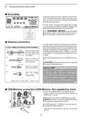
... SWR Each antenna is recommended before removing the USB-Memory* (p.12-25). The IC-7700 has an SWR meter to monitor the antenna SWR continuously. ■ USB-Memory connection (USB-Memory: Not supplied by Icom) Connect the USB-Memory* to a gas or electric pipe, since the connection ... Tin the 1-2 mm center conductor. In this case, an antenna tuner is higher than approx. 2.0:1, the transceiver's power drops to a long ground rod. Make sure to match the transceiver and antenna. Select antenna(s), such as solder shown at left. We recommend 1.5:1 or better of critical importance...
... SWR Each antenna is recommended before removing the USB-Memory* (p.12-25). The IC-7700 has an SWR meter to monitor the antenna SWR continuously. ■ USB-Memory connection (USB-Memory: Not supplied by Icom) Connect the USB-Memory* to a gas or electric pipe, since the connection ... Tin the 1-2 mm center conductor. In this case, an antenna tuner is higher than approx. 2.0:1, the transceiver's power drops to a long ground rod. Make sure to match the transceiver and antenna. Select antenna(s), such as solder shown at left. We recommend 1.5:1 or better of critical importance...
Instruction Manual
Page 31
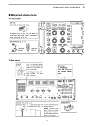
... cap when no antenna or external equipment is changed in keyer set mode. (p. 4-12) Microphones (p. 2-10) Optional SM-20 Optional HM-36 POWER HF/50MHz TRANSCEIVER i7700 TRANSMIT TUNER VOX BK-IN MONITOR MIC RF PWR KEY SPEED DELAY TIMER PHONES AGC SQL NR NB TX RX ELEC-KEY MIC AGC...
... cap when no antenna or external equipment is changed in keyer set mode. (p. 4-12) Microphones (p. 2-10) Optional SM-20 Optional HM-36 POWER HF/50MHz TRANSCEIVER i7700 TRANSMIT TUNER VOX BK-IN MONITOR MIC RF PWR KEY SPEED DELAY TIMER PHONES AGC SQL NR NB TX RX ELEC-KEY MIC AGC...
Instruction Manual
Page 32
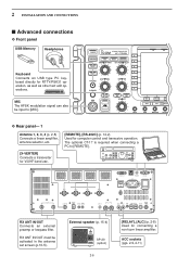
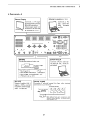
...]. 2 INSTALLATION AND CONNECTIONS ■ Advanced connections D Front panel USB-Memory Headphones Keyboard Connects an USB type PC keyboard directly for computer control and transceive operation. POWER HF/50MHz TRANSCEIVER i7700 TRANSMIT TUNER VOX BK-IN MONITOR MIC RF PWR KEY SPEED DELAY TIMER PHONES AGC SQL NR NB TX RX ELEC-KEY... REF I RX ANT OUT IN X-VERTER DC OUT 15V MAX1A EXT METER KEYPAD E X T- External speaker (p. 15-4) SP-20 (option) 2-6 [RELAY], [ALC] (p. 2-8) Used for connecting a non-Icom linear amplifier.
...]. 2 INSTALLATION AND CONNECTIONS ■ Advanced connections D Front panel USB-Memory Headphones Keyboard Connects an USB type PC keyboard directly for computer control and transceive operation. POWER HF/50MHz TRANSCEIVER i7700 TRANSMIT TUNER VOX BK-IN MONITOR MIC RF PWR KEY SPEED DELAY TIMER PHONES AGC SQL NR NB TX RX ELEC-KEY... REF I RX ANT OUT IN X-VERTER DC OUT 15V MAX1A EXT METER KEYPAD E X T- External speaker (p. 15-4) SP-20 (option) 2-6 [RELAY], [ALC] (p. 2-8) Used for connecting a non-Icom linear amplifier.
Instruction Manual
Page 33
...;5% ±5% ±5% S1 S2 S3 S4 (T1/M1) (T2/M2) (T3/M3) (T4/M4) Mute switch: Mutes both transmission and reception when switched ON during transceive operation, etc. 2-7 Video output signal can be turned ON and OFF in ACC set mode (p. 12-11) 2 INSTALLATION AND CONNECTIONS Ethernet connector (p. 16-6) Connects a PC...
...;5% ±5% ±5% S1 S2 S3 S4 (T1/M1) (T2/M2) (T3/M3) (T4/M4) Mute switch: Mutes both transmission and reception when switched ON during transceive operation, etc. 2-7 Video output signal can be turned ON and OFF in ACC set mode (p. 12-11) 2 INSTALLATION AND CONNECTIONS Ethernet connector (p. 16-6) Connects a PC...
Instruction Manual
Page 34
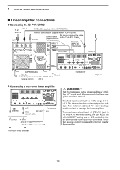
... (supplied with "MOSFET" setting (see p. 12-8 for details). Connect [INPUT2] if necessary Coaxial cable* REMOTE EXCITER 1 1&2 GND ANT1 ANT2 GND ACC 2 IC-PW1/EURO AC outlet Ground (Non-European versions: 100-120/220-240 V European version : 230 V) Transceiver *Optional D Connecting a non-Icom linear amplifier To an antenna ANT1 50 Ω RELAY coaxial cable...
... (supplied with "MOSFET" setting (see p. 12-8 for details). Connect [INPUT2] if necessary Coaxial cable* REMOTE EXCITER 1 1&2 GND ANT1 ANT2 GND ACC 2 IC-PW1/EURO AC outlet Ground (Non-European versions: 100-120/220-240 V European version : 230 V) Transceiver *Optional D Connecting a non-Icom linear amplifier To an antenna ANT1 50 Ω RELAY coaxial cable...
Instruction Manual
Page 40
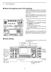
...INP ENT q Turn the main power ON with [I/O] on the rear panel. • The transceiver power is normal and does not indicate any equipment malfunction. ■ Initial settings After resetting the transceiver, set controls as shown in set mode settings after turning power ON. counter clockwise [DELAY] ...the set mode to turn power ON. • The CPU is reset. • The CPU start-up takes approx. 5 sec. • The transceiver displays its initial VFO frequencies when resetting is complete. w While pushing and holding F-INPENT and MW , push POWER to default values. clockwise [NB]...
...INP ENT q Turn the main power ON with [I/O] on the rear panel. • The transceiver power is normal and does not indicate any equipment malfunction. ■ Initial settings After resetting the transceiver, set controls as shown in set mode settings after turning power ON. counter clockwise [DELAY] ...the set mode to turn power ON. • The CPU is reset. • The CPU start-up takes approx. 5 sec. • The transceiver displays its initial VFO frequencies when resetting is complete. w While pushing and holding F-INPENT and MW , push POWER to default values. clockwise [NB]...
Instruction Manual
Page 43
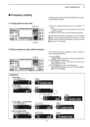
... ENT 850 kHz (0.85000 MHz) Push F-INP 50 GENE ENT 0 24 14 8 5 F-INP ENT 3-5 3 BASIC OPERATIONS ■ Frequency setting D Tuning with the keypad Keypad The transceiver has a keypad for convenient frequency tuning. q Push the desired band key on the keypad 1-3 times. • 3 different frequencies can be selected on each band with.... w Rotate the main dial to deactivate the lock function. (see p. 5-17 for details) D Direct frequency entry with the main dial Band keys Main dial The transceiver has several tuning methods for direct frequency entry as described below.
... ENT 850 kHz (0.85000 MHz) Push F-INP 50 GENE ENT 0 24 14 8 5 F-INP ENT 3-5 3 BASIC OPERATIONS ■ Frequency setting D Tuning with the keypad Keypad The transceiver has a keypad for convenient frequency tuning. q Push the desired band key on the keypad 1-3 times. • 3 different frequencies can be selected on each band with.... w Rotate the main dial to deactivate the lock function. (see p. 5-17 for details) D Direct frequency entry with the main dial Band keys Main dial The transceiver has several tuning methods for direct frequency entry as described below.
Instruction Manual
Page 55
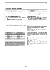
...transceiver to adjust the audio tone. D About 5 MHz band operation (USA version only) Operation on the 5 MHz band is allowed on 5 discrete frequencies and must adhere to set mode. It's your responsibility to the following: • USB mode • Maximum of 50 watts ERP (Effective Radiated Power) • 2.8 kHz bandwidth IC-7700...and hold [COMP] (MF6) for easy recall. *The FCC specifies center frequencies on the 5 MHz band. However, the IC-7700 displays carrier frequency. to select the compression bandwidth from wide, middle and narrow. • VOX (voice operated transmit) (p. ...
...transceiver to adjust the audio tone. D About 5 MHz band operation (USA version only) Operation on the 5 MHz band is allowed on 5 discrete frequencies and must adhere to set mode. It's your responsibility to the following: • USB mode • Maximum of 50 watts ERP (Effective Radiated Power) • 2.8 kHz bandwidth IC-7700...and hold [COMP] (MF6) for easy recall. *The FCC specifies center frequencies on the 5 MHz band. However, the IC-7700 displays carrier frequency. to select the compression bandwidth from wide, middle and narrow. • VOX (voice operated transmit) (p. ...
