Instruction Manual
Page 5
...; Required connections 2-5 D Front panel 2-5 D Rear panel 2-5 ■ Advanced connections 2-6 D Front panel 2-6 D Rear panel-1 2-6 D Rear panel-2 2-7 ■ Linear amplifier connections 2-8 D Connecting the IC-PW1/EURO 2-8 D Connecting a non-Icom linear amplifier 2-8 ■ Transverter jack information 2-9 ■ FSK and AFSK (SSTV) connections 2-9 ■ Microphone connector information 2-10 ■ Microphones (options 2-10 D SM-20 2-10 D HM-36...
...; Required connections 2-5 D Front panel 2-5 D Rear panel 2-5 ■ Advanced connections 2-6 D Front panel 2-6 D Rear panel-1 2-6 D Rear panel-2 2-7 ■ Linear amplifier connections 2-8 D Connecting the IC-PW1/EURO 2-8 D Connecting a non-Icom linear amplifier 2-8 ■ Transverter jack information 2-9 ■ FSK and AFSK (SSTV) connections 2-9 ■ Microphone connector information 2-10 ■ Microphones (options 2-10 D SM-20 2-10 D HM-36...
Instruction Manual
Page 16
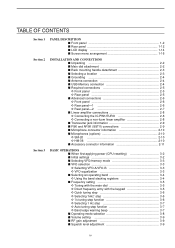
...(p. 10-2) ➥ Displays antenna selection memory when pushed and held for 1 sec. (p. 5-9) ✔ What is the preamp? When a transverter is used for 1 sec. • When the receive antenna is activated, the antenna connected to [ANT4] is in use, this [ANT] ...a desired signal from being distorted when very strong signals are near your location. 1-6 1 PANEL DESCRIPTION ■ Front panel (continued) #3 #4 #5 #6 #7 #8 #9 $0 $1 $2 NSCEIVER 7700 MONITOR D DELAY NB NB RF DRIVE TX RX SPLIT LOCK 1.8 1 10 4 21 7 GENE 3.5 2 14 5 24 8 50 0 MP-W MW 7 3 18 6 28 9 F-...
...(p. 10-2) ➥ Displays antenna selection memory when pushed and held for 1 sec. (p. 5-9) ✔ What is the preamp? When a transverter is used for 1 sec. • When the receive antenna is activated, the antenna connected to [ANT4] is in use, this [ANT] ...a desired signal from being distorted when very strong signals are near your location. 1-6 1 PANEL DESCRIPTION ■ Front panel (continued) #3 #4 #5 #6 #7 #8 #9 $0 $1 $2 NSCEIVER 7700 MONITOR D DELAY NB NB RF DRIVE TX RX SPLIT LOCK 1.8 1 10 4 21 7 GENE 3.5 2 14 5 24 8 50 0 MP-W MW 7 3 18 6 28 9 F-...
Instruction Manual
Page 23
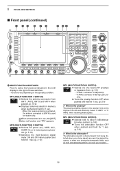
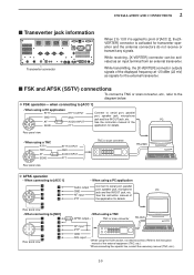
...ALC INPUT JACK [ALC] (p. 2-8) Connects to the ALC output jack of a non-Icom linear amplifier. !9 T/R CONTROL JACK [RELAY] (p. 2-8) Connects to ground when transmitting to [ACC 2] pin 6, or when the transverter function is connected, [RX ANT- Connected in parallel with MOSFET switching). @0 ACCESSORY SOCKET... circuit Receiver IN [RX ANT] OUT 1-13 When no external unit is in total) _ + _ @6 TRANSVERTER CONNECTOR [X-VERTER] (p. 2-6) External transverter input/output connector. Activated by the switching relay internally. IN] and [RX ANT- OUT] (p. 2-7) Connects external...
...ALC INPUT JACK [ALC] (p. 2-8) Connects to the ALC output jack of a non-Icom linear amplifier. !9 T/R CONTROL JACK [RELAY] (p. 2-8) Connects to ground when transmitting to [ACC 2] pin 6, or when the transverter function is connected, [RX ANT- Connected in parallel with MOSFET switching). @0 ACCESSORY SOCKET... circuit Receiver IN [RX ANT] OUT 1-13 When no external unit is in total) _ + _ @6 TRANSVERTER CONNECTOR [X-VERTER] (p. 2-6) External transverter input/output connector. Activated by the switching relay internally. IN] and [RX ANT- OUT] (p. 2-7) Connects external...
Instruction Manual
Page 27
...; Required connections 2-5 D Front panel 2-5 D Rear panel 2-5 ■ Advanced connections 2-6 D Front panel 2-6 D Rear panel-1 2-6 D Rear panel-2 2-7 ■ Linear amplifier connections 2-8 D Connecting the IC-PW1/EURO 2-8 D Connecting a non-Icom linear amplifier 2-8 ■ Transverter jack information 2-9 ■ FSK and AFSK (SSTV) connections 2-9 ■ Microphone connector information 2-10 ■ Microphones (options 2-10 D SM-20 2-10 D HM-36...
...; Required connections 2-5 D Front panel 2-5 D Rear panel 2-5 ■ Advanced connections 2-6 D Front panel 2-6 D Rear panel-1 2-6 D Rear panel-2 2-7 ■ Linear amplifier connections 2-8 D Connecting the IC-PW1/EURO 2-8 D Connecting a non-Icom linear amplifier 2-8 ■ Transverter jack information 2-9 ■ FSK and AFSK (SSTV) connections 2-9 ■ Microphone connector information 2-10 ■ Microphones (options 2-10 D SM-20 2-10 D HM-36...
Instruction Manual
Page 32
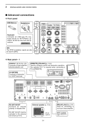
... RTTY/PSK DRIVE COMP MONI GAIN VOX GAIN D Rear panel- 1 Antenna 1, 2, 3, 4 (p. 2-8) Connects a linear amplifier, antenna selector, etc. [X-VERTER] Connects a transverter for V/UHF band use. [REMOTE], [RS-232C] (p. 14-2) Used for connecting a non-Icom linear amplifier. ANT 1 ANT 2 ANT 3 ANT 4 E X T- DISPL AY 15A GND REMOTE RS-232C AC I /O 10MHz -10dBm RX ANT IN...
... RTTY/PSK DRIVE COMP MONI GAIN VOX GAIN D Rear panel- 1 Antenna 1, 2, 3, 4 (p. 2-8) Connects a linear amplifier, antenna selector, etc. [X-VERTER] Connects a transverter for V/UHF band use. [REMOTE], [RS-232C] (p. 14-2) Used for connecting a non-Icom linear amplifier. ANT 1 ANT 2 ANT 3 ANT 4 E X T- DISPL AY 15A GND REMOTE RS-232C AC I /O 10MHz -10dBm RX ANT IN...
Instruction Manual
Page 35
...Audio output Connect to the instruction manual of the displayed frequency at -20 dBm (22 mV) as an input terminal from an external transverter. While transmitting, the [X-VERTER] connector outputs signals of the external equipment (TNC, etc.). †When connecting the squelch line, ... a PC application RTTY RTTY OUTPUT Connect to the diagram below. While receiving, [X-VERTER] connector can be activated as signals for transverter operation and the antenna connectors do not receive or transmit any signals. Refer to serial port, parallel GND port, speaker jack, microphone...
...Audio output Connect to the instruction manual of the displayed frequency at -20 dBm (22 mV) as an input terminal from an external transverter. While transmitting, the [X-VERTER] connector outputs signals of the external equipment (TNC, etc.). †When connecting the squelch line, ... a PC application RTTY RTTY OUTPUT Connect to the diagram below. While receiving, [X-VERTER] connector can be activated as signals for transverter operation and the antenna connectors do not receive or transmit any signals. Refer to serial port, parallel GND port, speaker jack, microphone...
Instruction Manual
Page 168
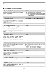
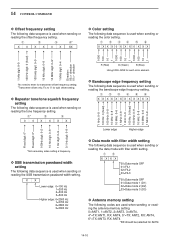
... automatically selected when the internal RTTY decoder is applied to [ACC2] pin 6. 12 SET MODE ■ Others set mode (continued) Transverter Function Selects the transverter operation condition from HIGH (faster) and LOW (slower). (default: HIGH) HIGH 12-14 There are reversed. • Normal : ... Reverse : Key open/close = Space/Mark PSK Tone Frequency Selects the desired PSK tone frequency for the transverter operation within 0.000 to 13.8 V DC is used . Transverter Offset Sets the desired offset frequency for the PSK reception from 1000, 1500 and 2000 Hz. (default: ...
... automatically selected when the internal RTTY decoder is applied to [ACC2] pin 6. 12 SET MODE ■ Others set mode (continued) Transverter Function Selects the transverter operation condition from HIGH (faster) and LOW (slower). (default: HIGH) HIGH 12-14 There are reversed. • Normal : ... Reverse : Key open/close = Space/Mark PSK Tone Frequency Selects the desired PSK tone frequency for the transverter operation within 0.000 to 13.8 V DC is used . Transverter Offset Sets the desired offset frequency for the PSK reception from 1000, 1500 and 2000 Hz. (default: ...
Instruction Manual
Page 193
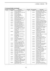
...details) Send/read split lock set (0=OFF, 1=ON) Send/read tuner auto start set (0=OFF, 1=ON) Send/read PTT tune set (0=OFF, 1=ON) Send/read transverter set (0=OFF, 1=15 min., 2=30 min., 3=60 min.) Set/read screen saver type (0=Bound, 1=Rotation, 2=Twist) Send/read output signal setting for external display ...1275 Hz, 1=1615 Hz, 2=2125 Hz) Send/read CLOCK2 name (up indication setting (0=OFF, 1=ON) Send/read screen saver set (0=OFF, 1=ON) Send/read transverter offset (see p. 14-9 for details) Send/read date (20000101=1st Jan. 2000 to 20991231=31st Dec. 2099) Send/read time (0000=00:00 to 2359...
...details) Send/read split lock set (0=OFF, 1=ON) Send/read tuner auto start set (0=OFF, 1=ON) Send/read PTT tune set (0=OFF, 1=ON) Send/read transverter set (0=OFF, 1=15 min., 2=30 min., 3=60 min.) Set/read screen saver type (0=Bound, 1=Rotation, 2=Twist) Send/read output signal setting for external display ...1275 Hz, 1=1615 Hz, 2=2125 Hz) Send/read CLOCK2 name (up indication setting (0=OFF, 1=ON) Send/read screen saver set (0=OFF, 1=ON) Send/read transverter offset (see p. 14-9 for details) Send/read date (20000101=1st Jan. 2000 to 20991231=31st Dec. 2099) Send/read time (0000=00:00 to 2359...
Instruction Manual
Page 198
... setting. direction 1000 100 10 1 1000 100 10 1 1000 100 10 1 R (Red) G (Green) B (Blue) Using 0000-0255 for each color element. *No need to '0' for transverter offset frequency setting. †Transverter offset only; Fix to enter for split offset setting.
... setting. direction 1000 100 10 1 1000 100 10 1 1000 100 10 1 R (Red) G (Green) B (Blue) Using 0000-0255 for each color element. *No need to '0' for transverter offset frequency setting. †Transverter offset only; Fix to enter for split offset setting.