

Instruction Manual
Page 3
... s Dial lock function 19 5 RECEIVE AND TRANSMIT 20 - 34 s Mode selection 20 s Squelch and RF gain 20 s Function for receive 21 s DSP function (option 23 s Filter selection 24 s Filter setting 25 s Function for transmit 26 s Split frequency operation 30 s SWR 30 s Function for...
... s Dial lock function 19 5 RECEIVE AND TRANSMIT 20 - 34 s Mode selection 20 s Squelch and RF gain 20 s Function for receive 21 s DSP function (option 23 s Filter selection 24 s Filter setting 25 s Function for transmit 26 s Split frequency operation 30 s SWR 30 s Function for...
Instruction Manual
Page 5
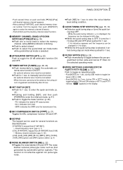
...➥ While the kHz quick tuning step is selected, it enters tuning step set mode when pushed for 1 sec. @0 FILTER SWITCH [FIL] (p. 24) ➥ Push momentarily to toggle between CW and CW reverse or RTTY and RTTY reverse. Memory channel selection.(pgs. 4, 35) • [V/M], [A=B], [A/B], [MW], [M-CL], [M&#...!8 NOISE BLANKER SWITCH [NB] (p. 22) ➥Toggles the noise blanker ON and OFF. during CW or RTTY mode, to toggle between the pre-programmed normal, wide and narrow IF filters for several times (or push and hold) [√ DN]/[UP ∫] until desired memory channel appears...
...➥ While the kHz quick tuning step is selected, it enters tuning step set mode when pushed for 1 sec. @0 FILTER SWITCH [FIL] (p. 24) ➥ Push momentarily to toggle between CW and CW reverse or RTTY and RTTY reverse. Memory channel selection.(pgs. 4, 35) • [V/M], [A=B], [A/B], [MW], [M-CL], [M&#...!8 NOISE BLANKER SWITCH [NB] (p. 22) ➥Toggles the noise blanker ON and OFF. during CW or RTTY mode, to toggle between the pre-programmed normal, wide and narrow IF filters for several times (or push and hold) [√ DN]/[UP ∫] until desired memory channel appears...
Instruction Manual
Page 7
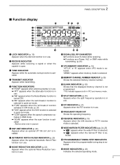
... (p. 23) Appears when the optional Automatic Notch Filter function is in use. !5 FREQUENCY READOUT Shows the operating frequency. !6 REVERSE INDICATOR (p.19) Appears when the CW reverse or RTTY reverse mode is selected. !7 WIDE/NARROW FILTER INDICATORS (pgs. 24, 25) ➥" " appears when the wide IF ...filter is selected. ➥" " appears when the narrow IF filter is selected. !8 PROGRAMMABLE TUNING STEP INDICATORS...
... (p. 23) Appears when the optional Automatic Notch Filter function is in use. !5 FREQUENCY READOUT Shows the operating frequency. !6 REVERSE INDICATOR (p.19) Appears when the CW reverse or RTTY reverse mode is selected. !7 WIDE/NARROW FILTER INDICATORS (pgs. 24, 25) ➥" " appears when the wide IF ...filter is selected. ➥" " appears when the narrow IF filter is selected. !8 PROGRAMMABLE TUNING STEP INDICATORS...
Instruction Manual
Page 25
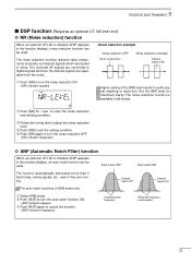
... [NR] indicator appears. w Push [ANF] to turn the noise reduction OFF. • [NR] indicator disappears. ï ANF (Automatic Notch Filter) function When an optional UT-106 is installed (DSP appears in noise. The noise reduction function is available in audio signal masking or distortion. e ...signals, etc., even if they are separated from the noise. • Noise reduction example Noise reduction OFF Noise components Noise reduction activated Desired signal (CW) q Push [NR] to turn the auto notch function ON. • [ANF] indicator appears. e Push [ANF] again to adjust the ...
... [NR] indicator appears. w Push [ANF] to turn the noise reduction OFF. • [NR] indicator disappears. ï ANF (Automatic Notch Filter) function When an optional UT-106 is installed (DSP appears in noise. The noise reduction function is available in audio signal masking or distortion. e ...signals, etc., even if they are separated from the noise. • Noise reduction example Noise reduction OFF Noise components Noise reduction activated Desired signal (CW) q Push [NR] to turn the auto notch function ON. • [ANF] indicator appears. e Push [ANF] again to adjust the ...
Instruction Manual
Page 26
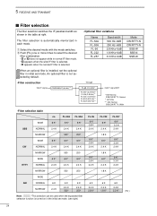
... switches. An optional filter is installed, set the optional filter in the table at right. Narrow, SSB/CW/RTTY; The filter selection is turned on in each mode. Wide • Filter selection table no FL-52A FL-53A WIDE 6 K* 6 K* 6 K* SSB NORMAL 2.4 K 2.4 K 2.4 K NARROW 500*... width 500 Hz/-6dB 250 Hz/-6dB 2.8 KHz/-6dB 1.8 KHz/-6dB 3.3 KHz/-6dB Mode CW/RTTY-N CW/RTTY-N SSB-W SSB-N SSB-W When an optional filter is not selected by default. • Filter construction 2nd IF signal CFWS450HT (6 kHz)*** Through FL-65 (2.4 kHz)* FL-257 (3.3 kHz)**...
... switches. An optional filter is installed, set the optional filter in the table at right. Narrow, SSB/CW/RTTY; The filter selection is turned on in each mode. Wide • Filter selection table no FL-52A FL-53A WIDE 6 K* 6 K* 6 K* SSB NORMAL 2.4 K 2.4 K 2.4 K NARROW 500*... width 500 Hz/-6dB 250 Hz/-6dB 2.8 KHz/-6dB 1.8 KHz/-6dB 3.3 KHz/-6dB Mode CW/RTTY-N CW/RTTY-N SSB-W SSB-N SSB-W When an optional filter is not selected by default. • Filter construction 2nd IF signal CFWS450HT (6 kHz)*** Through FL-65 (2.4 kHz)* FL-257 (3.3 kHz)**...
Instruction Manual
Page 27
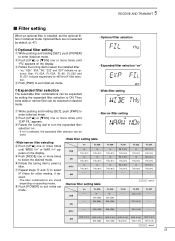
pears on operating modes. CW FL-222 no THU (6 K) no THU (6 K) no optional filter, FL-52A, FL-53A, FL-96, FL-222 and FL-257, indicate respectively for other modes, if de- e Rotate the tuning dial to ...K) no THU (6 K) no FL-52A SSB - - - FL-222 222 (1.8 K) 222 (1.8 K) FL-257 257(3.3 k) THU (6 K) 257(3.3 k) THU (6 K) 257(3.3 k) THU (6 K) - - - : default FL-257 - - - - - - 5 RECEIVE AND TRANSMIT s Filter setting When an optional filter is selected, the expanded filter selection can be selected on desired mode. • Wide filter setting q While...
pears on operating modes. CW FL-222 no THU (6 K) no THU (6 K) no optional filter, FL-52A, FL-53A, FL-96, FL-222 and FL-257, indicate respectively for other modes, if de- e Rotate the tuning dial to ...K) no THU (6 K) no FL-52A SSB - - - FL-222 222 (1.8 K) 222 (1.8 K) FL-257 257(3.3 k) THU (6 K) 257(3.3 k) THU (6 K) 257(3.3 k) THU (6 K) - - - : default FL-257 - - - - - - 5 RECEIVE AND TRANSMIT s Filter setting When an optional filter is selected, the expanded filter selection can be selected on desired mode. • Wide filter setting q While...
Instruction Manual
Page 31
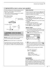
...pushing and holding [SET], push [PWR] to select "4". • AH-4 AUTOMATIC ANTENNA TUNER is required for 1 sec. • " " blinks and "CW" appears while tuning. w Push and hold [TUNER]" operation and activates first transmission on the transceiver directly. r To bypass the AH-4 manually, push ...to turn power ON. Tuning indicator; AH-4 setting example: For mobile operation Optional AH-2b antenna element For outdoor operation Long wire AH-4 IC-718 MODE FILTER TS PWR AF SQL RIT SHIFT MIC PHONES LOCK ˛ V/M1 A=B2 A/B3 MW4 M=C5L M V6 SP7L SCN8 VOX9 .NR ANF0...
...pushing and holding [SET], push [PWR] to select "4". • AH-4 AUTOMATIC ANTENNA TUNER is required for 1 sec. • " " blinks and "CW" appears while tuning. w Push and hold [TUNER]" operation and activates first transmission on the transceiver directly. r To bypass the AH-4 manually, push ...to turn power ON. Tuning indicator; AH-4 setting example: For mobile operation Optional AH-2b antenna element For outdoor operation Long wire AH-4 IC-718 MODE FILTER TS PWR AF SQL RIT SHIFT MIC PHONES LOCK ˛ V/M1 A=B2 A/B3 MW4 M=C5L M V6 SP7L SCN8 VOX9 .NR ANF0...
Instruction Manual
Page 58
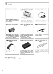
IC-MB5 MOBILE MOUNTING BRACKET CT-17 CI-V LEVEL CONVERTER AH-710 FOLDED DIPOLE ANTENNA approx. 24.5 m; 80.3 ft Transceiver mounting bracket for your convenience. • FL-52A: 500 Hz/-6dB (CW/RTTY narrow) • FL-53A: 250 Hz/-6dB (CW narrow) • FL-96: 2.8 KHz/-6dB (SSB wide) • FL-222: 1.8 KHz/-6dB... station operation. Covers from 1.9-30 MHz bands. 12 OPTIONS SP-7 EXTERNAL SPEAKER FL-52A, FL-53A, FL-96, FL-222 and FL-257 455 KHz FILTERS UT-106 DSP RECEIVE UNIT Compact speaker for portable operation.
IC-MB5 MOBILE MOUNTING BRACKET CT-17 CI-V LEVEL CONVERTER AH-710 FOLDED DIPOLE ANTENNA approx. 24.5 m; 80.3 ft Transceiver mounting bracket for your convenience. • FL-52A: 500 Hz/-6dB (CW/RTTY narrow) • FL-53A: 250 Hz/-6dB (CW narrow) • FL-96: 2.8 KHz/-6dB (SSB wide) • FL-222: 1.8 KHz/-6dB... station operation. Covers from 1.9-30 MHz bands. 12 OPTIONS SP-7 EXTERNAL SPEAKER FL-52A, FL-53A, FL-96, FL-222 and FL-257 455 KHz FILTERS UT-106 DSP RECEIVE UNIT Compact speaker for portable operation.


