
Instruction Manual
Page 2
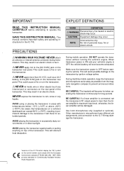
...the transceiver's RF output power to less than 16 V DC, such as possible from the magnetic navigation compass to the IC-718 may damage the transceiver. Use Icom microphones only (supplied or optional). This may occur. This could cause a fire or ruin the transceiver. CAUTION Equipment... electric shock. This will be damaged. During maritime mobile operation, keep the transceiver and microphone as far away as a 24 V battery, to the transceiver if left there for the IC-718. BE CAREFUL! If a linear amplifier is OFF before attempting to rain, snow or any...
...the transceiver's RF output power to less than 16 V DC, such as possible from the magnetic navigation compass to the IC-718 may damage the transceiver. Use Icom microphones only (supplied or optional). This may occur. This could cause a fire or ruin the transceiver. CAUTION Equipment... electric shock. This will be damaged. During maritime mobile operation, keep the transceiver and microphone as far away as a 24 V battery, to the transceiver if left there for the IC-718. BE CAREFUL! If a linear amplifier is OFF before attempting to rain, snow or any...

Instruction Manual
Page 3
q DC power cable 1 w Hand microphone (HM-36 1 e Fuse (FGB 20 A; for RTTY 33 6 MEMORY OPERATION 35 - 38 s Memory channels 35 s Memory channel ...er 1 1 TABLE OF CONTENTS IMPORTANT i EXPLICIT DEFINITIONS i PRECAUTIONS i 1 TABLE OF CONTENTS 1 SUPPLIED ACCESSORIES 1 2 PANEL DESCRIPTION 2 - 8 s Front panel 2 s Function display 5 s Rear panel 6 s Microphone (HM-36 8 3 INSTALLATION AND CONNECTIONS ......... 9 - 14 s Unpacking 9 s Selecting a location 9 s Grounding 9 s Antenna connection 9 s Required connections 10 s Advanced connections 11 s Power supply connections 12...
q DC power cable 1 w Hand microphone (HM-36 1 e Fuse (FGB 20 A; for RTTY 33 6 MEMORY OPERATION 35 - 38 s Memory channels 35 s Memory channel ...er 1 1 TABLE OF CONTENTS IMPORTANT i EXPLICIT DEFINITIONS i PRECAUTIONS i 1 TABLE OF CONTENTS 1 SUPPLIED ACCESSORIES 1 2 PANEL DESCRIPTION 2 - 8 s Front panel 2 s Function display 5 s Rear panel 6 s Microphone (HM-36 8 3 INSTALLATION AND CONNECTIONS ......... 9 - 14 s Unpacking 9 s Selecting a location 9 s Grounding 9 s Antenna connection 9 s Required connections 10 s Advanced connections 11 s Power supply connections 12...
Instruction Manual
Page 4
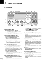
...at maxi- pgs. 20, 44) o MAIN DIAL Adjusts the squelch threshold level. mum) in advance. ➥ Push for microphone connector information. p. 21) ➥ Shifts the receive frequency without changing the transmit frequency. • Rotate the control clockwise to ...momentarily to turn power ON. tial set mode (p. 46). t RF GAIN/SQUELCH CONTROL [RF/SQL] (outer control; 2 PANEL DESCRIPTION s Front panel Speaker Function Display @1 @0 !9 !8 !7 IC-718 MODE FIL TS 1 2 3 V/M A=B A/B 4 5 6 MW M -CL ˛ M V q PWR AF RF/SQL RIT SHIFT MIC PHONES w LOCK 7 8 9 SPL SCN...
...at maxi- pgs. 20, 44) o MAIN DIAL Adjusts the squelch threshold level. mum) in advance. ➥ Push for microphone connector information. p. 21) ➥ Shifts the receive frequency without changing the transmit frequency. • Rotate the control clockwise to ...momentarily to turn power ON. tial set mode (p. 46). t RF GAIN/SQUELCH CONTROL [RF/SQL] (outer control; 2 PANEL DESCRIPTION s Front panel Speaker Function Display @1 @0 !9 !8 !7 IC-718 MODE FIL TS 1 2 3 V/M A=B A/B 4 5 6 MW M -CL ˛ M V q PWR AF RF/SQL RIT SHIFT MIC PHONES w LOCK 7 8 9 SPL SCN...
Instruction Manual
Page 10
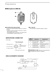
...continuously. • The [UP]/[DN] switch can damage the internal 8 V regulator. • HM-36 SCHEMATIC DIAGRAM MICROPHONE MICROPHONE CABLE MICROPHONE PLUG MIC ELEMENT + 10µ 2k 4700p + 0.33µ 4700p DOWN UP qu wiy ert PTT RECEIVE 470 TRANSMIT 8 ...release to receive. • MICROPHONE CONNECTOR (Front view) q Microphone input w +8 V DC output e Frequency up e Frequency down i Main readout AF output (varies with [AF]/[BAL]) u GND (Microphone ground) y GND (PTT ground) t PTT r Main readout squelch switch [MIC...
...continuously. • The [UP]/[DN] switch can damage the internal 8 V regulator. • HM-36 SCHEMATIC DIAGRAM MICROPHONE MICROPHONE CABLE MICROPHONE PLUG MIC ELEMENT + 10µ 2k 4700p + 0.33µ 4700p DOWN UP qu wiy ert PTT RECEIVE 470 TRANSMIT 8 ...release to receive. • MICROPHONE CONNECTOR (Front view) q Microphone input w +8 V DC output e Frequency up e Frequency down i Main readout AF output (varies with [AF]/[BAL]) u GND (Microphone ground) y GND (PTT ground) t PTT r Main readout squelch switch [MIC...
Instruction Manual
Page 12
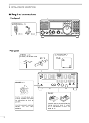
... used when the internal electronic keyer is turned OFF in "CW PADDL" in initial set mode. (p. 31) 3 INSTALLATION AND CONNECTIONS s Required connections • Front panel MICROPHONES (p. 55) HM-36 SM-20 IC-718 MODE FIL TS PWR AF RF/SQL RIT SHIFT MIC PHONES LOCK 1 2 3 V/M A=B A/B 4 5 6 MW M -
... used when the internal electronic keyer is turned OFF in "CW PADDL" in initial set mode. (p. 31) 3 INSTALLATION AND CONNECTIONS s Required connections • Front panel MICROPHONES (p. 55) HM-36 SM-20 IC-718 MODE FIL TS PWR AF RF/SQL RIT SHIFT MIC PHONES LOCK 1 2 3 V/M A=B A/B 4 5 6 MW M -
Instruction Manual
Page 28
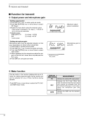
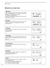
... set mode. DISPLAY INDICATION MEASUREMENT Po Indicates the relative RF output power. In such cases, reduce the microphone gain (see above). 5 RECEIVE AND TRANSMIT s Function for transmit ï Output power and microphone gain • Setting output power q Push [SET] for 1 sec. to enter the quick set mode...8226; Available power SSB/CW/RTTY: 2 (or less) -100 W AM: 2 (or less) -40 W* *Carrier power • Setting microphone gain Microphone gain must be selected for one of three functions during transmit. • Push [SET] one or more times to select "RF Power". e ...
... set mode. DISPLAY INDICATION MEASUREMENT Po Indicates the relative RF output power. In such cases, reduce the microphone gain (see above). 5 RECEIVE AND TRANSMIT s Function for transmit ï Output power and microphone gain • Setting output power q Push [SET] for 1 sec. to enter the quick set mode...8226; Available power SSB/CW/RTTY: 2 (or less) -100 W AM: 2 (or less) -40 W* *Carrier power • Setting microphone gain Microphone gain must be selected for one of three functions during transmit. • Push [SET] one or more times to select "RF Power". e ...
Instruction Manual
Page 29
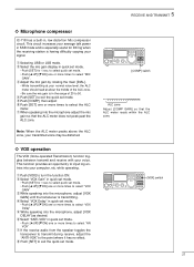
... within the ALC zone. ï VOX operation The VOX (Voice-operated Transmission) function toggles between transmit and receive with your signal. u When speaking into the microphone, adjust [VOX DELAY] as desired. w Select "VOX Gain" in quick set mode. • Push [SET] for 1 sec. i Push [SET] ... into the microphone, adjust [VOX GAIN] until the transceiver is in quick set mode. • Push [∫ UP]/[√ DN] one or more times to exit the quick set mode. q Selecting USB or LSB mode. 5 RECEIVE AND TRANSMIT ˛ ˛ ï Microphone compressor IC-718 has a built...
... within the ALC zone. ï VOX operation The VOX (Voice-operated Transmission) function toggles between transmit and receive with your signal. u When speaking into the microphone, adjust [VOX DELAY] as desired. w Select "VOX Gain" in quick set mode. • Push [SET] for 1 sec. i Push [SET] ... into the microphone, adjust [VOX GAIN] until the transceiver is in quick set mode. • Push [∫ UP]/[√ DN] one or more times to exit the quick set mode. q Selecting USB or LSB mode. 5 RECEIVE AND TRANSMIT ˛ ˛ ï Microphone compressor IC-718 has a built...
Instruction Manual
Page 33
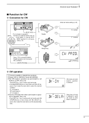
... 11 12 5678 SEND terminal for all bands. (See p. 33) 1234 ˛ ˛ See p. 32 for connection details: Paddle operation from front panel MIC connector. [MICROPHONE] 5 RECEIVE AND TRANSMIT Paddle Straight key Initial set the desired delay time. s Function for CW ï Connection for CW 13 9 10 11 12 5678 1234... such as above. Delay time of 6 dots is selected. w Select CW (or CW-REV) mode with [MODE]. to set mode setting (p. 45) : normal : reverse : off Microphone : UP/DN key ï CW operation q Connect a paddle or straight key as a foot switch;
... 11 12 5678 SEND terminal for all bands. (See p. 33) 1234 ˛ ˛ See p. 32 for connection details: Paddle operation from front panel MIC connector. [MICROPHONE] 5 RECEIVE AND TRANSMIT Paddle Straight key Initial set the desired delay time. s Function for CW ï Connection for CW 13 9 10 11 12 5678 1234... such as above. Delay time of 6 dots is selected. w Select CW (or CW-REV) mode with [MODE]. to set mode setting (p. 45) : normal : reverse : off Microphone : UP/DN key ï CW operation q Connect a paddle or straight key as a foot switch;
Instruction Manual
Page 35
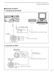
... Personal computer Rear panel view 13 9 10 11 12 5678 12 34 AF GND SQL*1 AF out SEND GND FSKK Use either the ACC or microphone connector. 13 9 10 11 12 5678 12 34 SQL*1 AF out AF in SEND GND *1Connect SQL line when required. 33 s Function for RTTY ï...
... Personal computer Rear panel view 13 9 10 11 12 5678 12 34 AF GND SQL*1 AF out SEND GND FSKK Use either the ACC or microphone connector. 13 9 10 11 12 5678 12 34 SQL*1 AF out AF in SEND GND *1Connect SQL line when required. 33 s Function for RTTY ï...
Instruction Manual
Page 44
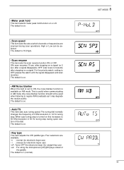
..., it can be adjusted from 0 to 99 and H for the VOX (voice activated transmit). The default is displayed automatically. • Mic gain This item adjusts microphone gain from 0 to 99 and H for the VOX (voice activated transmit) function. SE : Semi break-in operation available. 42 The delay time can be adjusted...
..., it can be adjusted from 0 to 99 and H for the VOX (voice activated transmit). The default is displayed automatically. • Mic gain This item adjusts microphone gain from 0 to 99 and H for the VOX (voice activated transmit) function. SE : Semi break-in operation available. 42 The delay time can be adjusted...
Instruction Manual
Page 47
... electronic keyer use) • r : reverse (for electronic keyer use) • oF : Turns OFF the electronic keyer (for straight key use) • ud : For using the microphone's [UP]/[DN] keys insted of the dial. Four selections are scanned during quick rotation of the paddle. The default is n (normal). OFF: scan soes not...
... electronic keyer use) • r : reverse (for electronic keyer use) • oF : Turns OFF the electronic keyer (for straight key use) • ud : For using the microphone's [UP]/[DN] keys insted of the dial. Four selections are scanned during quick rotation of the paddle. The default is n (normal). OFF: scan soes not...
Instruction Manual
Page 56
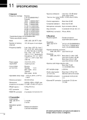
... below 30 MHz: -50 dB, above 30 MHz: -60 dB • Carrier suppression : More than 40 dB • Unwanted sideband : More than 50 dB • Microphone connector : 8-pin connector (600 Ω) • Key connector : 3-conductor 6.5 (d) mm (1⁄4˝) • SEND/ALC connector : Phono (RCA) D Receiver • Receive system : Double-conversion superheterodyne...
... below 30 MHz: -50 dB, above 30 MHz: -60 dB • Carrier suppression : More than 40 dB • Unwanted sideband : More than 50 dB • Microphone connector : 8-pin connector (600 Ω) • Key connector : 3-conductor 6.5 (d) mm (1⁄4˝) • SEND/ALC connector : Phono (RCA) D Receiver • Receive system : Double-conversion superheterodyne...
Instruction Manual
Page 57
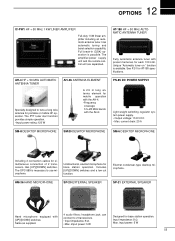
...MHz AUTOMATIC ANTENNA TUNER Specially designed to tune a long wire antenna for each 100 kHz. current drain: 20 A SM-8 DESKTOP MICROPHONE SM-20 DESKTOP MICROPHONE SM-6 DESKTOP MICROPHONE Including 2 connection cables for base station operation. The OPC-589 is necessary to 2 transceivers. • Input impedance: 8 Ω...SP-21 EXTERNAL SPEAKER Hand microphone equipped with preset memories for portable or mobile HF operation. Includes [UP]/[DOWN] switches and a low cut function. See P. 51 for AT-180 specifications. can connect to use microphone. 12 OPTIONS IC-PW1 HF + 50 MHz...
...MHz AUTOMATIC ANTENNA TUNER Specially designed to tune a long wire antenna for each 100 kHz. current drain: 20 A SM-8 DESKTOP MICROPHONE SM-20 DESKTOP MICROPHONE SM-6 DESKTOP MICROPHONE Including 2 connection cables for base station operation. The OPC-589 is necessary to 2 transceivers. • Input impedance: 8 Ω...SP-21 EXTERNAL SPEAKER Hand microphone equipped with preset memories for portable or mobile HF operation. Includes [UP]/[DOWN] switches and a low cut function. See P. 51 for AT-180 specifications. can connect to use microphone. 12 OPTIONS IC-PW1 HF + 50 MHz...