
Instruction Manual
Page 1
Operation is subject to the following two conditions: (1) This device may not cause harmful interference, and (2) this device must accept any interference received, including interference that may cause undesired operation. INSTRUCTION MANUAL HF ALL BAND TRANSCEIVER i718 This device complies with Part 15 of the FCC rules.
Operation is subject to the following two conditions: (1) This device may not cause harmful interference, and (2) this device must accept any interference received, including interference that may cause undesired operation. INSTRUCTION MANUAL HF ALL BAND TRANSCEIVER i718 This device complies with Part 15 of the FCC rules.
Instruction Manual
Page 16
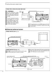
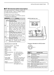
...cable supplied with the AT-180 [ACC] one of two AT-180 [ACC] connectors HF antenna IC-718 13 9 10 11 12 5678 1234 Ground 14 If this level is exceeded, a large external relay must be used. Turn the IC-718's power OFF when connecting the AT-180, otherwise, the CPU may malfunction and the... power and linear amplifier ALC output level referring to -4 V, and the transceiver does not accept positive voltage. To an antenna RF OUTPUT RF INPUT SEND ALC Non-Icom linear amplifier 50 Ω coaxial cable ANT IC-718 SEND 13 9 10 11 12 5678 1234 ALC The specifications for the SEND relay ...
...cable supplied with the AT-180 [ACC] one of two AT-180 [ACC] connectors HF antenna IC-718 13 9 10 11 12 5678 1234 Ground 14 If this level is exceeded, a large external relay must be used. Turn the IC-718's power OFF when connecting the AT-180, otherwise, the CPU may malfunction and the... power and linear amplifier ALC output level referring to -4 V, and the transceiver does not accept positive voltage. To an antenna RF OUTPUT RF INPUT SEND ALC Non-Icom linear amplifier 50 Ω coaxial cable ANT IC-718 SEND 13 9 10 11 12 5678 1234 ALC The specifications for the SEND relay ...
Instruction Manual
Page 30
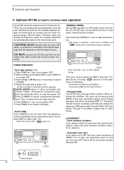
... [UP Y] or [Z DN] one or more times to the connected antenna automatically. of VSWR 1.5:1 or less, use "automatic tuner on HF bands at poor SWR's. CONVENIENT • Tuner sensitive condition If you change the frequency. Tuning indicator; 28 Then, re-select the tuner type...automatically during transmission, select the tuner sensitive condition. Y [TUNER] • Automatic tuner start manual tun- This will not be damage both the transceiver and the antenna tuner. In this case, check the following: • the antenna connection and feedline • the antenna SWR (p. 26;...
... [UP Y] or [Z DN] one or more times to the connected antenna automatically. of VSWR 1.5:1 or less, use "automatic tuner on HF bands at poor SWR's. CONVENIENT • Tuner sensitive condition If you change the frequency. Tuning indicator; 28 Then, re-select the tuner type...automatically during transmission, select the tuner sensitive condition. Y [TUNER] • Automatic tuner start manual tun- This will not be damage both the transceiver and the antenna tuner. In this case, check the following: • the antenna connection and feedline • the antenna SWR (p. 26;...
Instruction Manual
Page 31
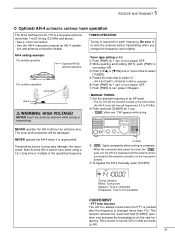
...will not transmit outside of the operating frequency. AH-4 setting example: For mobile operation Optional AH-2b antenna element For outdoor operation Long wire AH-4 IC-718 MODE FILTER TS PWR AF SQL RIT SHIFT MIC PHONES LOCK ˛ V/M1 A=B2 A/B3 MW4 M=C5L M V6 SP7L SCN8 VOX9 .NR ANF0...] for 1 sec. • " " blinks and "CW" appears while tuning. The tuner and transceiver will be tuned, the " " goes out, the AH-4 is bypassed and the antenna wire is turned ON in an HF band. • The IC-718 will tune all frequencies 3.5 to turn power OFF. to 30 MHz. Blinks: Tuning now...
...will not transmit outside of the operating frequency. AH-4 setting example: For mobile operation Optional AH-2b antenna element For outdoor operation Long wire AH-4 IC-718 MODE FILTER TS PWR AF SQL RIT SHIFT MIC PHONES LOCK ˛ V/M1 A=B2 A/B3 MW4 M=C5L M V6 SP7L SCN8 VOX9 .NR ANF0...] for 1 sec. • " " blinks and "CW" appears while tuning. The tuner and transceiver will be tuned, the " " goes out, the AH-4 is bypassed and the antenna wire is turned ON in an HF band. • The IC-718 will tune all frequencies 3.5 to turn power OFF. to 30 MHz. Blinks: Tuning now...
Instruction Manual
Page 49
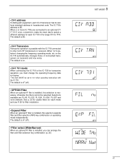
... filer is possible with the IC-735. on " when operating transceiver with the IC-718 connected to "on the IC-718 automatically changes those of connected transceivers (or receivers) and vice versa. The default is 5E. • CI-V Transceive Transceive operation is installed, this selection expands ... an optional IF filter is necessary, otherwise the filters cannot be set to other Icom HF transceivers or receivers. • CI-V address To distinguish equipment, each IC-718 in hexadecimal code. See p. 24 for usable filters for each mode and see P. 50 for ...
... filer is possible with the IC-735. on " when operating transceiver with the IC-718 connected to "on the IC-718 automatically changes those of connected transceivers (or receivers) and vice versa. The default is 5E. • CI-V Transceive Transceive operation is installed, this selection expands ... an optional IF filter is necessary, otherwise the filters cannot be set to other Icom HF transceivers or receivers. • CI-V address To distinguish equipment, each IC-718 in hexadecimal code. See p. 24 for usable filters for each mode and see P. 50 for ...
Instruction Manual
Page 53
... impedance : 50 Ω • Maximum input : 120 W power • Minimum tuning : 8 W power • Matching impedance : 16.7-150 Ω (HF band) range 20 -125 Ω (50 MHz band) • Tuning accuracy : Less than SWR 1.5:1 • Insertion loss : Less than 1.0 dB (after tuning...) • Power supply : 13.8 V DC/1 A (supplied from requirements the transceiver's ACC socket) • Dimensions (mm/in) : 167(W) × 58.6(H) × 225(D) 69⁄16(W) × 25⁄17(H) × 87⁄...
... impedance : 50 Ω • Maximum input : 120 W power • Minimum tuning : 8 W power • Matching impedance : 16.7-150 Ω (HF band) range 20 -125 Ω (50 MHz band) • Tuning accuracy : Less than SWR 1.5:1 • Insertion loss : Less than 1.0 dB (after tuning...) • Power supply : 13.8 V DC/1 A (supplied from requirements the transceiver's ACC socket) • Dimensions (mm/in) : 167(W) × 58.6(H) × 225(D) 69⁄16(W) × 25⁄17(H) × 87⁄...
Instruction Manual
Page 57
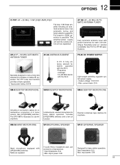
...input power: 5 W 55 12 OPTIONS IC-PW1 HF + 50 MHz 1 KW LINER AMPLIFIER Full-duty 1 kW linear amplifier including an automatic antenna tuner. The amplifier/power supply unit and the remote control unit are separated. AT-180 HF + 50 MHz AUTOMATIC ANTENNA TUNER Fully automatic...provides simple operation. • Input power rating: 120 W AH-2b ANTENNA ELEMENT A 2.5 m long antenna element for simultaneous connection of 2 transceivers. current drain: 20 A SM-8 DESKTOP MICROPHONE SM-20 DESKTOP MICROPHONE SM-6 DESKTOP MICROPHONE Including 2 connection cables for mobile operation with the ...
...input power: 5 W 55 12 OPTIONS IC-PW1 HF + 50 MHz 1 KW LINER AMPLIFIER Full-duty 1 kW linear amplifier including an automatic antenna tuner. The amplifier/power supply unit and the remote control unit are separated. AT-180 HF + 50 MHz AUTOMATIC ANTENNA TUNER Fully automatic...provides simple operation. • Input power rating: 120 W AH-2b ANTENNA ELEMENT A 2.5 m long antenna element for simultaneous connection of 2 transceivers. current drain: 20 A SM-8 DESKTOP MICROPHONE SM-20 DESKTOP MICROPHONE SM-6 DESKTOP MICROPHONE Including 2 connection cables for mobile operation with the ...

