

Instruction Manual
Page 3
... internal switch description 51 10 MAINTENANCE 52 - 53 s Troubleshooting 52 s Fuse replacement 53 s Resetting the CPU 53 11 SPECIFICATIONS 54 12 OPTIONS 55 - 56 13 CONTROL COMMAND 57 - 58 s Remote jack (CI-V) information 57 14 INTERNAL VIEWS 59 s Top view 59 s Bottom view 59 SUPPLIED ACCESSORIES q w The transceiver comes with the...
... internal switch description 51 10 MAINTENANCE 52 - 53 s Troubleshooting 52 s Fuse replacement 53 s Resetting the CPU 53 11 SPECIFICATIONS 54 12 OPTIONS 55 - 56 13 CONTROL COMMAND 57 - 58 s Remote jack (CI-V) information 57 14 INTERNAL VIEWS 59 s Top view 59 s Bottom view 59 SUPPLIED ACCESSORIES q w The transceiver comes with the...
Instruction Manual
Page 4
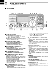
.... !0 PREAMP SWITCH [P.AMP] (p. 21) • The control can be set as the squelch plus RF gain controls or squelch control only (RF gain is fixed at maxi- announced. The squelch re- " " appears on . 2 mum) in advance. ➥ Push for 1 sec. 2 PANEL DESCRIPTION s Front panel Speaker Function Display @1 @0 !9 !8 !7 IC-718 MODE FIL TS 1 2 3 V/M A=B A/B 4 5 6 MW M -CL ˛...
.... !0 PREAMP SWITCH [P.AMP] (p. 21) • The control can be set as the squelch plus RF gain controls or squelch control only (RF gain is fixed at maxi- announced. The squelch re- " " appears on . 2 mum) in advance. ➥ Push for 1 sec. 2 PANEL DESCRIPTION s Front panel Speaker Function Display @1 @0 !9 !8 !7 IC-718 MODE FIL TS 1 2 3 V/M A=B A/B 4 5 6 MW M -CL ˛...
Instruction Manual
Page 8
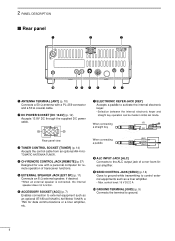
...Connects an 8 Ω external speaker, if desired. • When an external speaker is connected, the internal speaker does not function. o SEND CONTROL JACK [SEND] (p. 14) Goes to ground while transmitting to the ALC output jack of transceiver functions. w DC POWER SOCKET [DC 13.8V]... 10) Connects a 50 Ω antenna with a personal computer for remote operation of a non-Icom linear amplifier. When connecting a paddle (dot) (com) (dash) i ALC INPUT JACK [ALC] Connects to control external equipments such as an optional AT-180 AUTOMATIC ANTENNA TUNER, a TNC for use with a...
...Connects an 8 Ω external speaker, if desired. • When an external speaker is connected, the internal speaker does not function. o SEND CONTROL JACK [SEND] (p. 14) Goes to ground while transmitting to the ALC output jack of transceiver functions. w DC POWER SOCKET [DC 13.8V]... 10) Connects a 50 Ω antenna with a personal computer for remote operation of a non-Icom linear amplifier. When connecting a paddle (dot) (com) (dash) i ALC INPUT JACK [ALC] Connects to control external equipments such as an optional AT-180 AUTOMATIC ANTENNA TUNER, a TNC for use with a...
Instruction Manual
Page 9
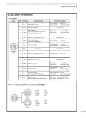
... voltage Output current : 8 V ±0.3 V : Less than 10 mA brown red Ground level Input current : -0.5 V to 0.8 V : Less than 20 mA orange yellow Output voltage : 0 to 8.0 V green Control voltage : -4 to ground when squelch opens. Goes to 0 V Input impedance : More than 6.0 V/100 µA green • When connecting the ACC conversion cable (OPC-599) 13...
... voltage Output current : 8 V ±0.3 V : Less than 10 mA brown red Ground level Input current : -0.5 V to 0.8 V : Less than 20 mA orange yellow Output voltage : 0 to 8.0 V green Control voltage : -4 to ground when squelch opens. Goes to 0 V Input impedance : More than 6.0 V/100 µA green • When connecting the ACC conversion cable (OPC-599) 13...
Instruction Manual
Page 13
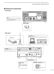
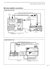
...-Icom linear amplifier. EXTERNAL SPEAKER (p. 55) SP-21, etc 11 3 INSTALLATION AND CONNECTIONS s Advanced connections • Front panel MIC The AFSK modulation signal can be input from [MIC]. (p. 33) IC-718 MODE FIL TS PWR AF RF/SQL RIT SHIFT MIC PHONES LOCK 1 2 3 V/M A=B A/B 4 5 6 MW M - ACC SOCKETS (p. 7) [SEND], [ALC] (p. 14) Used for computer control and...
...-Icom linear amplifier. EXTERNAL SPEAKER (p. 55) SP-21, etc 11 3 INSTALLATION AND CONNECTIONS s Advanced connections • Front panel MIC The AFSK modulation signal can be input from [MIC]. (p. 33) IC-718 MODE FIL TS PWR AF RF/SQL RIT SHIFT MIC PHONES LOCK 1 2 3 V/M A=B A/B 4 5 6 MW M - ACC SOCKETS (p. 7) [SEND], [ALC] (p. 14) Used for computer control and...
Instruction Manual
Page 15
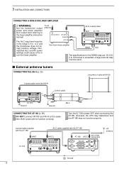
... 9 10 11 12 5678 1234 IC-718 CONNECTING THE IC-4KL Coaxial cable (supplied with the IC-4KL) ACC cable (supplied with the IC-4KL) OPC599 conversion cable (option) To an antenna ACC ANT ACC 13 9 10 11 12 5678 1234 IC-718 IC-4KL Remote controller Ground IC-4KL Remote control cable (supplied with the IC-4KL) AC outlet (220-240...
... 9 10 11 12 5678 1234 IC-718 CONNECTING THE IC-4KL Coaxial cable (supplied with the IC-4KL) ACC cable (supplied with the IC-4KL) OPC599 conversion cable (option) To an antenna ACC ANT ACC 13 9 10 11 12 5678 1234 IC-718 IC-4KL Remote controller Ground IC-4KL Remote control cable (supplied with the IC-4KL) AC outlet (220-240...
Instruction Manual
Page 16
...-4 at the same time. Both tuners will not function correctly. To an antenna RF OUTPUT RF INPUT SEND ALC Non-Icom linear amplifier 50 Ω coaxial cable ANT IC-718 SEND 13 9 10 11 12 5678 1234 ALC The specifications for the SEND relay are 16 V DC 2...A NON-ICOM LINER AMPLIFIER R WARNING: Set the transceiver output power and linear amplifier ALC output level referring to -4 V, and the transceiver does not accept positive voltage. s External antenna tuners CONNECTING THE AH-4 (p. 29) Long wire or optional AH-2b Coaxial cable (from the AH-4) Control cable IC-718 Ground Ground ...
...-4 at the same time. Both tuners will not function correctly. To an antenna RF OUTPUT RF INPUT SEND ALC Non-Icom linear amplifier 50 Ω coaxial cable ANT IC-718 SEND 13 9 10 11 12 5678 1234 ALC The specifications for the SEND relay are 16 V DC 2...A NON-ICOM LINER AMPLIFIER R WARNING: Set the transceiver output power and linear amplifier ALC output level referring to -4 V, and the transceiver does not accept positive voltage. s External antenna tuners CONNECTING THE AH-4 (p. 29) Long wire or optional AH-2b Coaxial cable (from the AH-4) Control cable IC-718 Ground Ground ...
Instruction Manual
Page 17
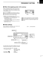
...;rst applying power (CPU resetting) Before first applying power, make sure all programmed contents in memory channels and returns programmed values in quick/initial set controls and switches as follows: • Quick tuning step indicator "w" : Push [TS]. • 1 Hz frequency readout : Push [TS] for 1 sec. (while quick tuning step is normal...
...;rst applying power (CPU resetting) Before first applying power, make sure all programmed contents in memory channels and returns programmed values in quick/initial set controls and switches as follows: • Quick tuning step indicator "w" : Push [TS]. • 1 Hz frequency readout : Push [TS] for 1 sec. (while quick tuning step is normal...
Instruction Manual
Page 22
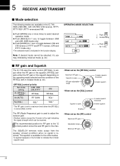
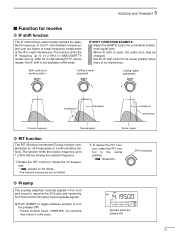
...The IC-718 uses the same control, [RF/SQL], to adjust either the RF gain or the squelch. [RF/SQL] adjusts either the RF gain or the squelch depending on the operating mode selected and the condition of the RF/SQL item in initiaset mode (p. 44). • [RF/SQL] control priority...gain adjustable range S-meter squelch threshold S-meter squelch • When set as the [RF] control Maximum RF gain Adjustable range Minimum RF gain 20 5 RECEIVE AND TRANSMIT s Mode selection The following modes are available in the IC-718: SSB (LSB/USB), CW, CW REV (CW reverse), RTTY, RTTY REV (RTTY reverse...
...The IC-718 uses the same control, [RF/SQL], to adjust either the RF gain or the squelch. [RF/SQL] adjusts either the RF gain or the squelch depending on the operating mode selected and the condition of the RF/SQL item in initiaset mode (p. 44). • [RF/SQL] control priority...gain adjustable range S-meter squelch threshold S-meter squelch • When set as the [RF] control Maximum RF gain Adjustable range Minimum RF gain 20 5 RECEIVE AND TRANSMIT s Mode selection The following modes are available in the IC-718: SSB (LSB/USB), CW, CW REV (CW reverse), RTTY, RTTY REV (RTTY reverse...
Instruction Manual
Page 23
... function shifts the receive frequency up ±250 Hz in the front end circuit to reject interference. w To cancel the RIT function, rotate the RIT control to cancel the off-frequencies. • " " appears on the display. • The transmit frequencies are not shifted. IF SHIFT OPERATION EXAMPLE •... preamp or turn the preamp OFF. • Preamp functions below 1.59999 MHz, but sensitivity may be changed. • Set the IF shift control to 1.2 KHz without moving the transmit frequency. The function shifts the IF frequency up to ±1.2 KHz in SSB/CW/RTTY modes and up...
... function shifts the receive frequency up ±250 Hz in the front end circuit to reject interference. w To cancel the RIT function, rotate the RIT control to cancel the off-frequencies. • " " appears on the display. • The transmit frequencies are not shifted. IF SHIFT OPERATION EXAMPLE •... preamp or turn the preamp OFF. • Preamp functions below 1.59999 MHz, but sensitivity may be changed. • Set the IF shift control to 1.2 KHz without moving the transmit frequency. The function shifts the IF frequency up to ±1.2 KHz in SSB/CW/RTTY modes and up...
Instruction Manual
Page 34
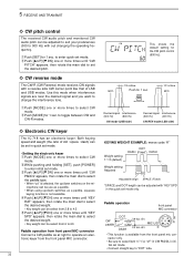
... ï CW reverse mode The CW-R (CW Reverse) mode receives CW signals with out changing the operating frequency. 5 RECEIVE AND TRANSMIT ï CW pitch control The received CW audio pitch and monitored CW audio pitch can be select from 2.8 to 4.5. t Push [∫ UP]/[√ DN] one or more times ... this mode when interference signals are near the desired signal and you want to toggle between CW and CW-R modes. ï Electronic CW keyer The IC-718 has an electronic keyer. q Push [MODE] one or more times until "KEY SPD" appears, then rotate the main dial to select CW mode. q Push...
... ï CW reverse mode The CW-R (CW Reverse) mode receives CW signals with out changing the operating frequency. 5 RECEIVE AND TRANSMIT ï CW pitch control The received CW audio pitch and monitored CW audio pitch can be select from 2.8 to 4.5. t Push [∫ UP]/[√ DN] one or more times ... this mode when interference signals are near the desired signal and you want to toggle between CW and CW-R modes. ï Electronic CW keyer The IC-718 has an electronic keyer. q Push [MODE] one or more times until "KEY SPD" appears, then rotate the main dial to select CW mode. q Push...
Instruction Manual
Page 42
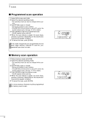
..." appears while scanning. e Set [RF/SQL] open or closed . • See previous page for scan condition. • If the [RF/SQL] control function is set as RF control, the squelch always opens. e Set [RF/SQL] open or closed . • See previous page for scan condition. • If the [RF/SQL...] control function is set as RF control, the squelch always opens. t When the scan detects a signal, the scan stops, pauses or ignores it depending on the resume setting and...
..." appears while scanning. e Set [RF/SQL] open or closed . • See previous page for scan condition. • If the [RF/SQL] control function is set as RF control, the squelch always opens. e Set [RF/SQL] open or closed . • See previous page for scan condition. • If the [RF/SQL...] control function is set as RF control, the squelch always opens. t When the scan detects a signal, the scan stops, pauses or ignores it depending on the resume setting and...
Instruction Manual
Page 46
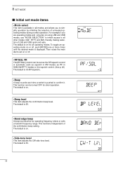
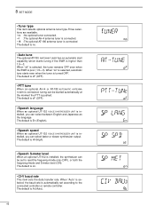
... AM modes; The default is on or off . • RF/SQL VR The [RF/SQL] control can be set as the RF/squelch control or automatic (acts as RF in SSB/CW/RTTY modes) or the squelch control. (See p. 20) The default is rS (RF/squelch). • Beep A beep sounds each time a switch...
... AM modes; The default is on or off . • RF/SQL VR The [RF/SQL] control can be set as the RF/squelch control or automatic (acts as RF in SSB/CW/RTTY modes) or the squelch control. (See p. 20) The default is rS (RF/squelch). • Beep A beep sounds each time a switch...
Instruction Manual
Page 48
... tune The optional AT-180 ANTENNA TUNER has an automatic start capability which starts tuning if the SWR is automatically set to the connected controller or remote controller. The default is oF (OFF). • Speech language When an optional UT-102 VOICE SYNTHESIZER UNIT is installed, the synthesizer can select between English...
... tune The optional AT-180 ANTENNA TUNER has an automatic start capability which starts tuning if the SWR is automatically set to the connected controller or remote controller. The default is oF (OFF). • Speech language When an optional UT-102 VOICE SYNTHESIZER UNIT is installed, the synthesizer can select between English...
Instruction Manual
Page 54
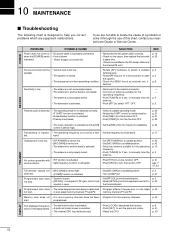
...MIC GAIN] to a suitable position. • Turn [COMP] off. • Set [RF/SQL] to the threshold point. • Reset [RF/SQL] control assignment and set mode. • Reset the CPU. listening level. • The squelch is activated. • Select a suitable operating mode. • Rotate the SHIFT...are installed in the transmitting condition. • Check the SEND line of this chart, contact your nearest Icom Dealer or Service Center. not stop. • [RF/SQL] is assigned to RF gain control and squelch is selected. • The internal CPU has malfunctioned. • Push [LOCK] to ...
...MIC GAIN] to a suitable position. • Turn [COMP] off. • Set [RF/SQL] to the threshold point. • Reset [RF/SQL] control assignment and set mode. • Reset the CPU. listening level. • The squelch is activated. • Select a suitable operating mode. • Rotate the SHIFT...are installed in the transmitting condition. • Check the SEND line of this chart, contact your nearest Icom Dealer or Service Center. not stop. • [RF/SQL] is assigned to RF gain control and squelch is selected. • The internal CPU has malfunctioned. • Push [LOCK] to ...
Instruction Manual
Page 57
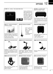
12 OPTIONS IC-PW1 HF + 50 MHz 1 KW LINER AMPLIFIER Full-duty 1 kW linear amplifier including an automatic antenna tuner. current drain: 20 A SM-8 DESKTOP MICROPHONE SM-20 ...; Max. AT-180 HF + 50 MHz AUTOMATIC ANTENNA TUNER Fully automatic antenna tuner with [UP]/[DOWN] switches. The amplifier/power supply unit and the remote control unit are separated. can connect to use microphone. headphone jack; Has automatic tuning and band selection capability.
12 OPTIONS IC-PW1 HF + 50 MHz 1 KW LINER AMPLIFIER Full-duty 1 kW linear amplifier including an automatic antenna tuner. current drain: 20 A SM-8 DESKTOP MICROPHONE SM-20 ...; Max. AT-180 HF + 50 MHz AUTOMATIC ANTENNA TUNER Fully automatic antenna tuner with [UP]/[DOWN] switches. The amplifier/power supply unit and the remote control unit are separated. can connect to use microphone. headphone jack; Has automatic tuning and band selection capability.
Instruction Manual
Page 58
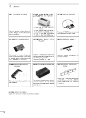
... frequency stability. • Frequency stability: ±0.5 ppm Carrying handle, convenient for base station operation. Height can change frequencies, operating mode, memory channels, etc. IC-MB5 MOBILE MOUNTING BRACKET CT-17 CI-V LEVEL CONVERTER AH-710 FOLDED DIPOLE ANTENNA approx. 24.5 m; 80.3 ft Transceiver mounting bracket for your convenience. •...KHz/-6dB (SSB narrow) • FL-257: 3.3 KHz/-6dB (SSB wide) Provides AF DSP functions such as noise reduction and auto notch. For remote receiver control using a personal computer. You can be adjusted for mobile operation.
... frequency stability. • Frequency stability: ±0.5 ppm Carrying handle, convenient for base station operation. Height can change frequencies, operating mode, memory channels, etc. IC-MB5 MOBILE MOUNTING BRACKET CT-17 CI-V LEVEL CONVERTER AH-710 FOLDED DIPOLE ANTENNA approx. 24.5 m; 80.3 ft Transceiver mounting bracket for your convenience. •...KHz/-6dB (SSB narrow) • FL-257: 3.3 KHz/-6dB (SSB wide) Provides AF DSP functions such as noise reduction and auto notch. For remote receiver control using a personal computer. You can be adjusted for mobile operation.
Instruction Manual
Page 59
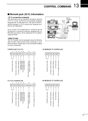
...Icom CI-V transceivers or receivers can be connected to command numbers. Data formats differ according to a personal computer equipped with an RS-232C port. 13 CONTROL COMMAND s Remote jack (CI-V) information • CI-V connection example The transceiver can be operated using the following functions of message code (fixed) 57 IC-718... ˛ ˛ BC-25 (optional) 9-15 V DC ct- 17 personal computer mini-plug cable CONTROLLER TO IC-718 q wert y u FE FE 5E E0 Cn Sc Data area FD OK MESSAGE TO CONTROLLER FE FE E0 5E FB FD Preamble...
...Icom CI-V transceivers or receivers can be connected to command numbers. Data formats differ according to a personal computer equipped with an RS-232C port. 13 CONTROL COMMAND s Remote jack (CI-V) information • CI-V connection example The transceiver can be operated using the following functions of message code (fixed) 57 IC-718... ˛ ˛ BC-25 (optional) 9-15 V DC ct- 17 personal computer mini-plug cable CONTROLLER TO IC-718 q wert y u FE FE 5E E0 Cn Sc Data area FD OK MESSAGE TO CONTROLLER FE FE E0 5E FB FD Preamble...
Instruction Manual
Page 60
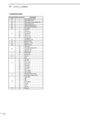
13 CONTROL COMMAND • Command table Command Sub command 00 - 01 - 02 - 03 - 04 - 05 - 06 - - 00 07 01 A0 B0 - 08 - 09 - 0A - 0B - 00 01 ...
13 CONTROL COMMAND • Command table Command Sub command 00 - 01 - 02 - 03 - 04 - 05 - 06 - - 00 07 01 A0 B0 - 08 - 09 - 0A - 0B - 00 01 ...