

Instruction Manual
Page 3
... VOICE SYNTHESIZER UNIT 49 s UT-106 DSP RECEIVE UNIT 50 s Optional IF filters 50 s AT-180 internal switch description 51 10 MAINTENANCE 52 - 53 s Troubleshooting 52 s Fuse replacement 53 s Resetting the CPU 53 11 SPECIFICATIONS 54 12 OPTIONS 55 - 56 13 CONTROL COMMAND 57 - 58 s Remote jack (CI-V) information 57...
... VOICE SYNTHESIZER UNIT 49 s UT-106 DSP RECEIVE UNIT 50 s Optional IF filters 50 s AT-180 internal switch description 51 10 MAINTENANCE 52 - 53 s Troubleshooting 52 s Fuse replacement 53 s Resetting the CPU 53 11 SPECIFICATIONS 54 12 OPTIONS 55 - 56 13 CONTROL COMMAND 57 - 58 s Remote jack (CI-V) information 57...
Instruction Manual
Page 54
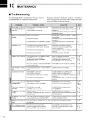
... channels have been programmed • Program different frequencies in the transmitting condition. • Check the SEND line of this chart, contact your nearest Icom Dealer or Service Center. If you correct problems which are equipment malfunctions. p. 20 p. 21 p. 21 p. 22 • The noise reduction ... an external unit, if p. 6 desired. distorted. • [COMP] function is activated. memory channels P1 and P2. 10 MAINTENANCE s Troubleshooting The following chart is designed to help you are not able to locate the cause of a problem or solve it to exit the quick set...
... channels have been programmed • Program different frequencies in the transmitting condition. • Check the SEND line of this chart, contact your nearest Icom Dealer or Service Center. If you correct problems which are equipment malfunctions. p. 20 p. 21 p. 21 p. 22 • The noise reduction ... an external unit, if p. 6 desired. distorted. • [COMP] function is activated. memory channels P1 and P2. 10 MAINTENANCE s Troubleshooting The following chart is designed to help you are not able to locate the cause of a problem or solve it to exit the quick set...