
Instruction Manual
Page 1
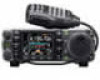
INSTRUCTION MANUAL HF/VHF/UHF ALL MODE TRANSCEIVER i7000
INSTRUCTION MANUAL HF/VHF/UHF ALL MODE TRANSCEIVER i7000
Instruction Manual
Page 163
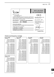
... requirements of the Radio and Telecommunications Terminal Equipment Directive, 1999/5/EC, and that any applicable Essential Test Suite measurements have been performed. Kind of equipment: HF/VHF/UHF ALL MODE TRANSCEIVER Type-designation: i7000 Version (where applicable): This compliance is based on our sole responsibility that this equipment complies with the following harmonised standards, speci... MHz 50.000-52.000000 MHz 144.000-146.00000 MHz 430.000-440.00000 MHz 21 154 ABOUT CE 21 DECLARATION OF CONFORMITY We Icom Inc.
... requirements of the Radio and Telecommunications Terminal Equipment Directive, 1999/5/EC, and that any applicable Essential Test Suite measurements have been performed. Kind of equipment: HF/VHF/UHF ALL MODE TRANSCEIVER Type-designation: i7000 Version (where applicable): This compliance is based on our sole responsibility that this equipment complies with the following harmonised standards, speci... MHz 50.000-52.000000 MHz 144.000-146.00000 MHz 430.000-440.00000 MHz 21 154 ABOUT CE 21 DECLARATION OF CONFORMITY We Icom Inc.

Service Manual
Page 1
SERVICE MANUAL HF/VHF/UHF ALL MODE TRANSCEIVER S-14214HZ-C1 Dec. 2005
SERVICE MANUAL HF/VHF/UHF ALL MODE TRANSCEIVER S-14214HZ-C1 Dec. 2005
Service Manual
Page 2
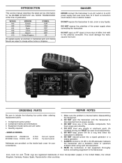
...or a sweep generator. 7. Quantity required 5030002820 LCD LTA025A161A IC-7000 8810009610 Screw FH M2.6 × 6 ZK IC-7000 Front unit 5 pieces Top cover10 pieces Addresses are registered trademarks of the power supply when connecting the transceiver. VER.NO. #02 #03 #04 #05 #08 ... equipment to the transceiver. ALWAYS connect a 50 dB to include the following four points when ordering replacement parts: 1. 10-digit Icom parts number 2. INTRODUCTION This service manual describes the latest service information for the IC-7000 HF/VHF/UHF ALL MODE TRANSCEIVER at the time ...
...or a sweep generator. 7. Quantity required 5030002820 LCD LTA025A161A IC-7000 8810009610 Screw FH M2.6 × 6 ZK IC-7000 Front unit 5 pieces Top cover10 pieces Addresses are registered trademarks of the power supply when connecting the transceiver. VER.NO. #02 #03 #04 #05 #08 ... equipment to the transceiver. ALWAYS connect a 50 dB to include the following four points when ordering replacement parts: 1. 10-digit Icom parts number 2. INTRODUCTION This service manual describes the latest service information for the IC-7000 HF/VHF/UHF ALL MODE TRANSCEIVER at the time ...

Service Manual
Page 11
...(D406, D407), high-pass filter (L413, L414, C428, C429, C431, C433), low-pass filter (L601-L603, C601, C602) and [ANT2] connector (CHASSIS; The VHF and UHF RF power amplified signal from IC1601 (pin 1) controls the IF amplifiers (Q701, Q901). IC960, pins 1, 3) and applied to the ALC amplifier (IC1601, pins 8, 9) ... and is turn ON and shifts the "POCV" voltage to adjust the TX output power for the AM mode (maximum; 40 W for HF/50 MHz bands, 20 W for VHF band, 14 W for the transceiver to output a constant RF power set by the RF power setting even when the supplied voltage shifts, etc...
...(D406, D407), high-pass filter (L413, L414, C428, C429, C431, C433), low-pass filter (L601-L603, C601, C602) and [ANT2] connector (CHASSIS; The VHF and UHF RF power amplified signal from IC1601 (pin 1) controls the IF amplifiers (Q701, Q901). IC960, pins 1, 3) and applied to the ALC amplifier (IC1601, pins 8, 9) ... and is turn ON and shifts the "POCV" voltage to adjust the TX output power for the AM mode (maximum; 40 W for HF/50 MHz bands, 20 W for VHF band, 14 W for the transceiver to output a constant RF power set by the RF power setting even when the supplied voltage shifts, etc...


