
Product Datasheet
Page 1
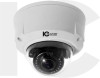
ICIP-D5000VIR 5 Megapixel Motorized IR Dome Network Camera This durable vandal dome contains an impressive 5 Megapixel Progressive Scan CMOS sensor, capable of outputting a crisp, clear high res image. The optics are a motorized 4 - 9mm vari-focal lens. This camera is also compatible with an audio input for external microphones, alarm I/O's, and support for PoE power. This camera is fully accessible via the entire ICR software suite, and is IK 10, IP 66...
ICIP-D5000VIR 5 Megapixel Motorized IR Dome Network Camera This durable vandal dome contains an impressive 5 Megapixel Progressive Scan CMOS sensor, capable of outputting a crisp, clear high res image. The optics are a motorized 4 - 9mm vari-focal lens. This camera is also compatible with an audio input for external microphones, alarm I/O's, and support for PoE power. This camera is fully accessible via the entire ICR software suite, and is IK 10, IP 66...
Product Datasheet
Page 2
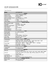
... Shutter Speed Min. Illumination S/N Ratio Video Output Max. D1/CIF (1 ~ 25/30fps) H.264: 32K ~ 8192Kbps Audio G.711a / G.711u / PCM 1/1 channel In/Out Network RJ-45 (10/100Base-T) IPv4/IPv6, HTTP, HTTPS, SSL, TCP/IP, UDP, UPnP, ICMP, IGMP, SNMP, RTSP, RTP, SMTP, NTP, DHCP, DNS, PPPOE, DDNS, FTP, IP Filter, QoS, Bonjour ONVIF, PSIA, CGI 20 users iPhone, iPad, Android, Windows Phone Auxiliary...
... Shutter Speed Min. Illumination S/N Ratio Video Output Max. D1/CIF (1 ~ 25/30fps) H.264: 32K ~ 8192Kbps Audio G.711a / G.711u / PCM 1/1 channel In/Out Network RJ-45 (10/100Base-T) IPv4/IPv6, HTTP, HTTPS, SSL, TCP/IP, UDP, UPnP, ICMP, IGMP, SNMP, RTSP, RTP, SMTP, NTP, DHCP, DNS, PPPOE, DDNS, FTP, IP Filter, QoS, Bonjour ONVIF, PSIA, CGI 20 users iPhone, iPad, Android, Windows Phone Auxiliary...

Product Manual
Page 1
HD (IR) Vandal Proof Network Dome Camera User's Manual Version 1.6.0
HD (IR) Vandal Proof Network Dome Camera User's Manual Version 1.6.0

Product Manual
Page 3
... fires or electrical shock caused by the qualified service engineers. Always follow the instruction guide the manufacturer recommended. 4.Qualified engineers needed All the examination and repair work . Please keep the sound ventilation. We assume no liability or responsibility for any problems caused by unauthorized modifications or attempted repair. 5.Environment This series network camera should be grounded to further enhance the...
... fires or electrical shock caused by the qualified service engineers. Always follow the instruction guide the manufacturer recommended. 4.Qualified engineers needed All the examination and repair work . Please keep the sound ventilation. We assume no liability or responsibility for any problems caused by unauthorized modifications or attempted repair. 5.Environment This series network camera should be grounded to further enhance the...
Product Manual
Page 5
...1.2 Features...1 1.3 Specifications ...2 1.3.1 Performance...2 2 Structure ...4 2.1 Dimensions...4 2.2 Port Description ...4 2.3 Bidirectional talk...10 2.3.1 Device-end to PC-end 10 2.3.2 PC-end to the Device-end 10 2.4 Alarm Setup...11 3 Installation...13 3.1 Device Installation Introduction 13 3.2 Device Installation Steps 13 3.2.1 Manual Zoom Lens Focus Operation 17 3.2.2 Side Cable Exit ...18 3.2.3 Cable Connection 18 3.3 Micro SD Card Installation 20 4 Quick Configuration Tool...21 4.1 Overview ...21 4.2 Operation ...21 5 Web Operation...23 5.1 Network Connection 23 5.2 Login and...
...1.2 Features...1 1.3 Specifications ...2 1.3.1 Performance...2 2 Structure ...4 2.1 Dimensions...4 2.2 Port Description ...4 2.3 Bidirectional talk...10 2.3.1 Device-end to PC-end 10 2.3.2 PC-end to the Device-end 10 2.4 Alarm Setup...11 3 Installation...13 3.1 Device Installation Introduction 13 3.2 Device Installation Steps 13 3.2.1 Manual Zoom Lens Focus Operation 17 3.2.2 Side Cable Exit ...18 3.2.3 Cable Connection 18 3.3 Micro SD Card Installation 20 4 Quick Configuration Tool...21 4.1 Overview ...21 4.2 Operation ...21 5 Web Operation...23 5.1 Network Connection 23 5.2 Login and...

Product Manual
Page 6
... used lonely, you can guarantee the proper work performance under heavy strike. Warning! Do not connect these two power supplying sources to external local alarm input and video detect as user pre- It supports analog video output and dual-way bidirectional talk. Management Support central server backup function in accordance with your configuration and setup in alarm or schedule setting Storage Support record via Web and the recorded file are storage...
... used lonely, you can guarantee the proper work performance under heavy strike. Warning! Do not connect these two power supplying sources to external local alarm input and video detect as user pre- It supports analog video output and dual-way bidirectional talk. Management Support central server backup function in accordance with your configuration and setup in alarm or schedule setting Storage Support record via Web and the recorded file are storage...

Product Manual
Page 7
... stream statistics, log, and software version. Assistant Function Log function Support PAL/NTSC Day/Night mode auto switch (electromagnetic ICR switch). Support iris auto adjust. Built-in device damage! It is adjustable. Model Parameter ICIP D5000AVIR System Main Processor High performance DSP OS Embedded LINUX System Resources Support real-time network, local record, and remote operation at the same time. Auto Iris DC drive Gain Control Manual/Auto Video Parameter White Balance Manual/Auto BLC...
... stream statistics, log, and software version. Assistant Function Log function Support PAL/NTSC Day/Night mode auto switch (electromagnetic ICR switch). Support iris auto adjust. Built-in device damage! It is adjustable. Model Parameter ICIP D5000AVIR System Main Processor High performance DSP OS Embedded LINUX System Resources Support real-time network, local record, and remote operation at the same time. Auto Iris DC drive Gain Control Manual/Auto Video Parameter White Balance Manual/Auto BLC...

Product Manual
Page 8
... title, time title, motion detect, tampering, overlay. [email protected] motorized zoom focus lens φ 14 interface. Max 1f/s snapshot. sensitivity level ranges from 0 to 100; Activation event, alarm device, audio/video storage, image snapshot, log, email function and etc. 1-channel input,1-channel output Manual>External alarm >Video detect>Schedule Support Micro SD card storage, NAS storage 1-channel wire Ethernet port, 10/100 Base-T Ethernet HTTP,TCP,ARP,RTSP,RTP,UDP,RTCP,SMTP,FTP,DHCP,DNS,DDNS,PP POE,IPv4...
... title, time title, motion detect, tampering, overlay. [email protected] motorized zoom focus lens φ 14 interface. Max 1f/s snapshot. sensitivity level ranges from 0 to 100; Activation event, alarm device, audio/video storage, image snapshot, log, email function and etc. 1-channel input,1-channel output Manual>External alarm >Video detect>Schedule Support Micro SD card storage, NAS storage 1-channel wire Ethernet port, 10/100 Base-T Ethernet HTTP,TCP,ARP,RTSP,RTP,UDP,RTCP,SMTP,FTP,DHCP,DNS,DDNS,PP POE,IPv4...
Product Manual
Page 14
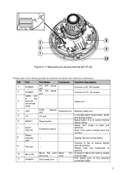
... realize local storage. 11 POWER 12V power port / The power port of the external connected cable. 9 SN Port Port Name Connector Function Description 1 POWER AC 24V port power / 2 POWER DC 12V port power / Cable exit of view and 7 AUTO FOCUS 5-direction button / definition. Adjust lens angle of the 3 external / / connected cable Connect to restore factory default setup. Please note this function. It is optional. 10 Micro SD Micro SD card Micro slot entry card SD Connect to Micro SD card to reduce device 9 Fan port / / internal problem.
... realize local storage. 11 POWER 12V power port / The power port of the external connected cable. 9 SN Port Port Name Connector Function Description 1 POWER AC 24V port power / 2 POWER DC 12V port power / Cable exit of view and 7 AUTO FOCUS 5-direction button / definition. Adjust lens angle of the 3 external / / connected cable Connect to restore factory default setup. Please note this function. It is optional. 10 Micro SD Micro SD card Micro slot entry card SD Connect to Micro SD card to reduce device 9 Fan port / / internal problem.

Product Manual
Page 15
.... Login the Web and then click the Talk button to enable the bidirectional talk function. Output alarm signal to standard Ethernet port. Support PoE. Ground end. Click Talk button again to stop the bidirectional talk function. Please refer to the following sheet for I /O Port 5 6 7 8 ALARM_IN GND AUDIO_IN AUDIO_OUT GND Alarm input port. Port Name Cable SN Cable Port Name Function Description Alarm output port. It can connect to TV monitor to view video. 2.3 Bidirectional...
.... Login the Web and then click the Talk button to enable the bidirectional talk function. Output alarm signal to standard Ethernet port. Support PoE. Ground end. Click Talk button again to stop the bidirectional talk function. Please refer to the following sheet for I /O Port 5 6 7 8 ALARM_IN GND AUDIO_IN AUDIO_OUT GND Alarm input port. Port Name Cable SN Cable Port Name Function Description Alarm output port. It can connect to TV monitor to view video. 2.3 Bidirectional...

Product Manual
Page 16
... connected to the alarm output port (No.1 pin) and alarm output public port (No.2 pin). When the input signal is idle or grounded, the device can select the corresponding type (NO/NC.) 4) Set the WEB alarm output. Please follow the steps listed below for the alarm output port of the I /O cable. 2) Connect the alarm output device to the 5V or is the No.1 pin of the device. Listening Operation...
... connected to the alarm output port (No.1 pin) and alarm output public port (No.2 pin). When the input signal is idle or grounded, the device can select the corresponding type (NO/NC.) 4) Set the WEB alarm output. Please follow the steps listed below for the alarm output port of the I /O cable. 2) Connect the alarm output device to the 5V or is the No.1 pin of the device. Listening Operation...

Product Manual
Page 19
... wall according to the monitor area. Then please follow the prompt on the dome camera enclosure to open it on the installation surface according to the installation positioning map. Please dig three bottom holes of the plastic expansion bolts according to remove the 2 inner hex screws from the dome driver module. Step 3 Please remove the device cable (Provided) network port and the power...
... wall according to the monitor area. Then please follow the prompt on the dome camera enclosure to open it on the installation surface according to the installation positioning map. Please dig three bottom holes of the plastic expansion bolts according to remove the 2 inner hex screws from the dome driver module. Step 3 Please remove the device cable (Provided) network port and the power...

Product Manual
Page 20
... driver module back to the metal hooks of the chassis to enhance the reliability of the rear panel. Step 6 15 Then use the inner hex wrench to secure the two inner hex screws to the cable exit of the installation surface. Take three ST3.0 self-tapping screws and secure them in Step 1. The GND screw thread specification is secure...
... driver module back to the metal hooks of the chassis to enhance the reliability of the rear panel. Step 6 15 Then use the inner hex wrench to secure the two inner hex screws to the cable exit of the installation surface. Take three ST3.0 self-tapping screws and secure them in Step 1. The GND screw thread specification is secure...
Product Manual
Page 22
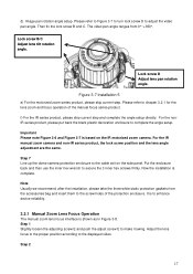
... white static protection gaskets from 0°~+350°. f) For the IR series product, please skip current step and complete the angle setup directly. Then fix the lock screw B and C. Figure 3-7 Installation 5 e) For the motorized zoom series product, please skip current step. It is to adjust the video pan angle. Adjust the lens focus to the proper position according to chapter 3.2.1 for the lens zoom and focus operation...
... white static protection gaskets from 0°~+350°. f) For the IR series product, please skip current step and complete the angle setup directly. Then fix the lock screw B and C. Figure 3-7 Installation 5 e) For the motorized zoom series product, please skip current step. It is to adjust the video pan angle. Adjust the lens focus to the proper position according to chapter 3.2.1 for the lens zoom and focus operation...

Product Manual
Page 23
... push the adjust screw F to adjust the video slightly. Adjust the lens to form a cable exit. Now secure the tunnel in Figure 3-9 to get a clear video. Please secure the adjust screw E if you can see the video may need to remove the plastic decoration plug from the side panel of the chassis and pull through the cable to dig through the part specified in the...
... push the adjust screw F to adjust the video slightly. Adjust the lens to form a cable exit. Now secure the tunnel in Figure 3-9 to get a clear video. Please secure the adjust screw E if you can see the video may need to remove the plastic decoration plug from the side panel of the chassis and pull through the cable to dig through the part specified in the...

Product Manual
Page 26
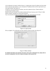
... "Open Device Web" item; 4 Quick Configuration Tool 4.1 Overview Quick configuration tool can view device IP address, port number, subnet mask, default gateway, MAC address and etc. At the same time, you can see an interface is shown as in the device web interface, you want to modify the device IP address without logging in Figure 4-2. Please note the tool only applies to the corresponding web login interface...
... "Open Device Web" item; 4 Quick Configuration Tool 4.1 Overview Quick configuration tool can view device IP address, port number, subnet mask, default gateway, MAC address and etc. At the same time, you can see an interface is shown as in the device web interface, you want to modify the device IP address without logging in Figure 4-2. Please note the tool only applies to the corresponding web login interface...
Product Manual
Page 27
... the Quick Configuration Tool User's Manual included in Web Network interface. In the configuration tool search interface (Figure 4-1), please select a device IP address and then double click it to login. See Figure 4-4. Or you cannot login the device. Figure 4-4 Main interface For detailed information and operation instruction of the quick configuration tool, please refer to the login interface. Otherwise, you can view device IP address, user name, password and port.
... the Quick Configuration Tool User's Manual included in Web Network interface. In the configuration tool search interface (Figure 4-1), please select a device IP address and then double click it to login. See Figure 4-4. Or you cannot login the device. Figure 4-4 Main interface For detailed information and operation instruction of the quick configuration tool, please refer to the login interface. Otherwise, you can view device IP address, user name, password and port.
Product Manual
Page 28
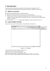
... the address bar. See Figure 5- 1. Please input your password after you first login. 23 Default factory name is admin and password is 192.168.1.108. Gateway is 255.255.255.0. Note: For security reasons, please modify your user name and password. Web includes several modules: Monitor channel preview, system configuration, alarm and etc. 5.1 Network Connection Please follow the steps listed below . See Figure 5- 2. 5 Web Operation This series network camera products support the Web access...
... the address bar. See Figure 5- 1. Please input your password after you first login. 23 Default factory name is admin and password is 192.168.1.108. Gateway is 255.255.255.0. Note: For security reasons, please modify your user name and password. Web includes several modules: Monitor channel preview, system configuration, alarm and etc. 5.1 Network Connection Please follow the steps listed below . See Figure 5- 2. 5 Web Operation This series network camera products support the Web access...

Product Manual
Page 29
Please refer to the Web Operation Manual included in unit. Figure 5- 3 Web monitoring window 24 See Figure 5- 3. Figure 5- 2 Web login After you successfully logged in, please install WEB plug-in the resource CD for detailed operation instruction.
Please refer to the Web Operation Manual included in unit. Figure 5- 3 Web monitoring window 24 See Figure 5- 3. Figure 5- 2 Web login After you successfully logged in, please install WEB plug-in the resource CD for detailed operation instruction.
Product Manual
Page 30
... card Do not set the Micro SD card as the storage media to restore factory default setup. It may damage the Micro SD card duration. media. Audio function Please use active device for at least five seconds to storage the write times schedule record file. When network upgrade operation failed, you remove the lightproof ring. 25 Usually we recommend the 4GB (or higher) or industry-level high speed card...
... card Do not set the Micro SD card as the storage media to restore factory default setup. It may damage the Micro SD card duration. media. Audio function Please use active device for at least five seconds to storage the write times schedule record file. When network upgrade operation failed, you remove the lightproof ring. 25 Usually we recommend the 4GB (or higher) or industry-level high speed card...


