
Hard Drive Specifications
Page 5
... Data Sheet 8 3.3 Performance Characteristics 9 3.3.1 Command Overhead 9 3.3.2 Mechanical Positioning 9 3.3.3 Drive Ready Time 11 3.3.4 Data Transfer Speed 12 3.3.5 Throughput 13 3.3.6 Operating Mode Definition 14 ...M A Timings 27 6.2.4 Ultra D M A Timings 29 6.2.5 Addressing of H D D Registers 37 6.2.6 Cabling 37 6.3 Jumper Settings 38 6.3.1 Location of Jumper Pin 38 6.3.2 Jumper Pin Assignment 38 6.3.3 Jumper Function 38 6.3.4 Jumper Set Position 39 6.4 Environment 43 6.5 DC Power Requirements 44 6.5.1 Start Up Current 46 6.6 Reliability 48 6.6.1 Contact Start Stop (CSS...
... Data Sheet 8 3.3 Performance Characteristics 9 3.3.1 Command Overhead 9 3.3.2 Mechanical Positioning 9 3.3.3 Drive Ready Time 11 3.3.4 Data Transfer Speed 12 3.3.5 Throughput 13 3.3.6 Operating Mode Definition 14 ...M A Timings 27 6.2.4 Ultra D M A Timings 29 6.2.5 Addressing of H D D Registers 37 6.2.6 Cabling 37 6.3 Jumper Settings 38 6.3.1 Location of Jumper Pin 38 6.3.2 Jumper Pin Assignment 38 6.3.3 Jumper Function 38 6.3.4 Jumper Set Position 39 6.4 Environment 43 6.5 DC Power Requirements 44 6.5.1 Start Up Current 46 6.6 Reliability 48 6.6.1 Contact Start Stop (CSS...

Hard Drive Specifications
Page 15
... 1. For jumper setting, refer to 6.3, "Jumper Settings" on page 38. © Copyright IBM Corp. 1998 7 3.0 Drive Characteristics This chapter provides the characteristics of the drives. 3.1 Default Logical Drive Parameter Default of logical drive parameters in column of Word 3 (Head) of Word 3 (Head) can be changed by jumper. Default Drive Parameters Model Capacity Word 1 Word 3 Word 6 (GB) (Cyl) (Head) (Sect/Trk) DTTA-351680 16...
... 1. For jumper setting, refer to 6.3, "Jumper Settings" on page 38. © Copyright IBM Corp. 1998 7 3.0 Drive Characteristics This chapter provides the characteristics of the drives. 3.1 Default Logical Drive Parameter Default of logical drive parameters in column of Word 3 (Head) of Word 3 (Head) can be changed by jumper. Default Drive Parameters Model Capacity Word 1 Word 3 Word 6 (GB) (Cyl) (Head) (Sect/Trk) DTTA-351680 16...

Hard Drive Specifications
Page 46
... 2GB (Default Logical Head 16) Disable Auto Spin (Default Logical Head 16) 38 OEM Specifications for DTTA-3xxxxx 6.3 Jumper Settings 6.3.1 Location of Jumper Pin Jumper pins are prepared for jumper setting. / / / / / / / / / I are located between power pins and AT interface pins. Jumper Pin Assignment 6.3.3 Jumper Function Device 0, Device 1, Cable Select, and Device 0 Forcing Device 1 Present can be selected exclussively with...
... 2GB (Default Logical Head 16) Disable Auto Spin (Default Logical Head 16) 38 OEM Specifications for DTTA-3xxxxx 6.3 Jumper Settings 6.3.1 Location of Jumper Pin Jumper pins are prepared for jumper setting. / / / / / / / / / I are located between power pins and AT interface pins. Jumper Pin Assignment 6.3.3 Jumper Function Device 0, Device 1, Cable Select, and Device 0 Forcing Device 1 Present can be selected exclussively with...

Hard Drive Specifications
Page 47
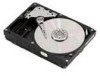
... SELECT is specified, AT interface signal #28 CSEL is referred to determin the drive address as follows: When CSEL is grounded or at a high level, the drive address is 0 (Device0). 6.3.4 Jumper Set Position 6.3.4.1 For Default Logical Head 16 I G E C A H F D B I G E C A H F D B I G E C A H F D B I G E C A H F D B DEVICE 0 < Shipping Default except DTTA 350640/350430 DEVICE 1 CABLE SELECT DEVICE 0 Forcing DEVICE 1 PRESENT Figure 31. When...
... SELECT is specified, AT interface signal #28 CSEL is referred to determin the drive address as follows: When CSEL is grounded or at a high level, the drive address is 0 (Device0). 6.3.4 Jumper Set Position 6.3.4.1 For Default Logical Head 16 I G E C A H F D B I G E C A H F D B I G E C A H F D B I G E C A H F D B DEVICE 0 < Shipping Default except DTTA 350640/350430 DEVICE 1 CABLE SELECT DEVICE 0 Forcing DEVICE 1 PRESENT Figure 31. When...
Hard Drive Specifications
Page 48
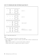
Jumper Block Setting Position Notes: 1. All other setting. 2. 6.3.4.2 For Default Logical Head 15 I G E C A H F D B I G E C A H F D B I G E C A H F D B I G E C A H F D B DEVICE 0 < Shipping Default for DTTA-3xxxxx When CSEL is open or at a low level, the drive address is 1 (Device1). 40 OEM Specifications for DTTA 350640/350430 DEVICE 1 CABLE SELECT DEVICE 0 Forcing DEVICE 1 PRESENT Figure 32. When CABLE SELECT is specified, AT interface signal #28...
Jumper Block Setting Position Notes: 1. All other setting. 2. 6.3.4.2 For Default Logical Head 15 I G E C A H F D B I G E C A H F D B I G E C A H F D B I G E C A H F D B DEVICE 0 < Shipping Default for DTTA-3xxxxx When CSEL is open or at a low level, the drive address is 1 (Device1). 40 OEM Specifications for DTTA 350640/350430 DEVICE 1 CABLE SELECT DEVICE 0 Forcing DEVICE 1 PRESENT Figure 32. When CABLE SELECT is specified, AT interface signal #28...
Hard Drive Specifications
Page 49
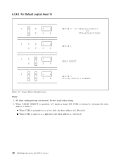
... drive address is 1 (Device1). Specification 41 When CABLE SELECT is specified, AT interface signal #28 CSEL is 0 (Device0). When CSEL is open or at a low level, the drive address is referred to 2GB with Default Logical Head 16 I G E C A H F D B I G E C A H F D B I G E C A H F D B I G E C A H F D B DEVICE 0 DEVICE 1 CABLE SELECT DEVICE 0 Forcing DEVICE 1 PRESENT Figure 33. All other setting. 2. Jumper Block Setting Position...
... drive address is 1 (Device1). Specification 41 When CABLE SELECT is specified, AT interface signal #28 CSEL is 0 (Device0). When CSEL is open or at a low level, the drive address is referred to 2GB with Default Logical Head 16 I G E C A H F D B I G E C A H F D B I G E C A H F D B I G E C A H F D B DEVICE 0 DEVICE 1 CABLE SELECT DEVICE 0 Forcing DEVICE 1 PRESENT Figure 33. All other setting. 2. Jumper Block Setting Position...
Hard Drive Specifications
Page 50
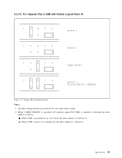
... is 0 (Device0). 6.3.4.4 For Disabling Auto Spin with Default Logical Head 16 I G E C A H F D B I G E C A H F D B I G E C A H F D B I G E C A H F D B DEVICE 0 DEVICE 1 CABLE SELECT DEVICE 0 Forcing DEVICE 1 PRESENT Figure 34. Do not make other setting patterns are reserved. When CSEL is open or at a low level, the drive address is 1 (Device1). 42 OEM Specifications for DTTA-3xxxxx Jumper Block Setting Position Notes: 1. All other...
... is 0 (Device0). 6.3.4.4 For Disabling Auto Spin with Default Logical Head 16 I G E C A H F D B I G E C A H F D B I G E C A H F D B I G E C A H F D B DEVICE 0 DEVICE 1 CABLE SELECT DEVICE 0 Forcing DEVICE 1 PRESENT Figure 34. Do not make other setting patterns are reserved. When CSEL is open or at a low level, the drive address is 1 (Device1). 42 OEM Specifications for DTTA-3xxxxx Jumper Block Setting Position Notes: 1. All other...


