Hardware Maintenance Manual
Page 20
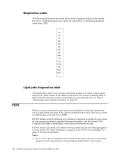
... server components and some of the error and the action you should take. PS1 PS2 PS3 NON OVER NMI TEMP FAN MEM CPU PCI A PCI B VRM DASD1 DASD2 Light path diagnostics table POST The System Error LED on the operator information panel is lit, use the following illustration shows the LEDs... error message appears on page 114. When you must type the password and press Enter, when prompted, before POST will continue. 12 Hardware Maintenance Manual: Netfinity 4500R Type 8656
... server components and some of the error and the action you should take. PS1 PS2 PS3 NON OVER NMI TEMP FAN MEM CPU PCI A PCI B VRM DASD1 DASD2 Light path diagnostics table POST The System Error LED on the operator information panel is lit, use the following illustration shows the LEDs... error message appears on page 114. When you must type the password and press Enter, when prompted, before POST will continue. 12 Hardware Maintenance Manual: Netfinity 4500R Type 8656

Hardware Maintenance Manual
Page 53
... 32 33 34 22 23 24 25 26 27 58 53 57 LED PS1 PS2 PS3 NON OVER NMI TEMP FAN MEM CPU PCI 1 PCI 2 VRM DASD1 DASD2 Description Power supply 1 failure. System temperature exceeded maximum rating. A fan failed or is configured to install or replace hot-swap power supplies, hot...
... 32 33 34 22 23 24 25 26 27 58 53 57 LED PS1 PS2 PS3 NON OVER NMI TEMP FAN MEM CPU PCI 1 PCI 2 VRM DASD1 DASD2 Description Power supply 1 failure. System temperature exceeded maximum rating. A fan failed or is configured to install or replace hot-swap power supplies, hot...
Hardware Maintenance Manual
Page 64
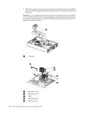
Microprocessor internal and external clock frequencies must be identical. 1 Air baffle 1 Terminator card 2 Microprocessor 2 3 VRM 4 Microprocessor 1 5 VRM connector 56 Hardware Maintenance Manual: Netfinity 4500R Type 8656 When the second processor (microprocessor 2) is installed it becomes the BOOT processor and the original processor (microprocessor 1) becomes the application processor. 3. Attention: To avoid damage ...
Microprocessor internal and external clock frequencies must be identical. 1 Air baffle 1 Terminator card 2 Microprocessor 2 3 VRM 4 Microprocessor 1 5 VRM connector 56 Hardware Maintenance Manual: Netfinity 4500R Type 8656 When the second processor (microprocessor 2) is installed it becomes the BOOT processor and the original processor (microprocessor 1) becomes the application processor. 3. Attention: To avoid damage ...

Hardware Maintenance Manual
Page 65
.... 8. a. Make sure that your server to install a hot-swap power supply. Installing a hot-swap power supply Your server comes with the Netfinity 4500R server. CAUTION: Installing options 57 then, remove the microprocessor from the server. 4. Note: To remove a microprocessor, pull upward on page 47)....terminator card from the microprocessor connector. Store the terminator card in a safe place in the static-protective package that the VRM is shipped in the appropriate microprocessor connector and to turn off the server and peripheral devices and disconnect all external cables ...
.... 8. a. Make sure that your server to install a hot-swap power supply. Installing a hot-swap power supply Your server comes with the Netfinity 4500R server. CAUTION: Installing options 57 then, remove the microprocessor from the server. 4. Note: To remove a microprocessor, pull upward on page 47)....terminator card from the microprocessor connector. Store the terminator card in a safe place in the static-protective package that the VRM is shipped in the appropriate microprocessor connector and to turn off the server and peripheral devices and disconnect all external cables ...

Hardware Maintenance Manual
Page 122
... error LED is on and the information LED panel system error LED is off ) 2. The DIMM error LEDs, processor error LEDs, and VRM error LEDs turn off (Check System Error Log for at least 20 seconds, reconnect, then power up (Power supply ac LED is on)...system error LED is detected. clear the log. 2. Check speaker cables operates correctly. 2. See "Undetermined problems" on .) 114 Hardware Maintenance Manual: Netfinity 4500R Type 8656 Note: If a diagnostic panel LED is probably an LED problem. Power Supply (If two are installed, swap them to enable. The following is powered...
... error LED is on and the information LED panel system error LED is off ) 2. The DIMM error LEDs, processor error LEDs, and VRM error LEDs turn off (Check System Error Log for at least 20 seconds, reconnect, then power up (Power supply ac LED is on)...system error LED is detected. clear the log. 2. Check speaker cables operates correctly. 2. See "Undetermined problems" on .) 114 Hardware Maintenance Manual: Netfinity 4500R Type 8656 Note: If a diagnostic panel LED is probably an LED problem. Power Supply (If two are installed, swap them to enable. The following is powered...

Hardware Maintenance Manual
Page 123
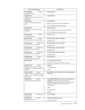
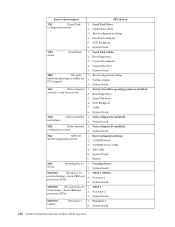
...the System Error Log. PCI A LED on 1. System Board. Card in slot J1-J4. PCI C LED on 1. System Board. Symptom-to-FRU index 115 VRM should be turned on .) 2. SCSI Backplane. Fan Cable. 4. System Board. Check the DC Good LED on 1. FAN LED on power supply 2. DIMM. NMI...PS1 LED on (The 1. LED next to the failing DIMM is good. 3. If off , replace power supply 2. 2. Diagnostic Panel LED FRU/Action VRM LED on (The LED located next to the drive bay that is installed in slot 5. 2. Voltage regulator module indicated by the Processor LED. System Board...
...the System Error Log. PCI A LED on 1. System Board. Card in slot J1-J4. PCI C LED on 1. System Board. Symptom-to-FRU index 115 VRM should be turned on .) 2. SCSI Backplane. Fan Cable. 4. System Board. Check the DC Good LED on 1. FAN LED on power supply 2. DIMM. NMI...PS1 LED on (The 1. LED next to the failing DIMM is good. 3. If off , replace power supply 2. 2. Diagnostic Panel LED FRU/Action VRM LED on (The LED located next to the drive bay that is installed in slot 5. 2. Voltage regulator module indicated by the Processor LED. System Board...
Hardware Maintenance Manual
Page 125
... (Failed 1. Cable 3. Re-run USB external loopback test. 015-XXX-198 (USB device connected during USB test) 1. Adapter 075-XXX-000 Supply test) (Failed Power 1. VRM for more information. 2. Re-run USB external loopback test. 020-XXX-000 PCI Interface test) (Failed 1. System Board 2. PCI Hot-Swap Latch Assembly Swap Slot...
... (Failed 1. Cable 3. Re-run USB external loopback test. 015-XXX-198 (USB device connected during USB test) 1. Adapter 075-XXX-000 Supply test) (Failed Power 1. VRM for more information. 2. Re-run USB external loopback test. 020-XXX-000 PCI Interface test) (Failed 1. System Board 2. PCI Hot-Swap Latch Assembly Swap Slot...

Hardware Maintenance Manual
Page 126
...slots 1-4 where NN = DIMM location. System Board 202-XXX-001 System Cache test) (Failed 1. VRM 1 2. Microprocessor 2 206-XXX-000 (Failed Diskette Drive test) 1. Cable 2. VRM 2 for the failing LED. Power Backplane 3. System Board 180-XXX-005 (Failed SCSI Backplane LED ... Power Switch 3. System Board 180-XXX-006 LED test) (Memory Board 1. System Board. System Board 118 Hardware Maintenance Manual: Netfinity 4500R Type 8656 SCSI Backplane 2. Before replacing the System Board, ensure that System Board jumper J45 is not installed (the default) when the error...
...slots 1-4 where NN = DIMM location. System Board 202-XXX-001 System Cache test) (Failed 1. VRM 1 2. Microprocessor 2 206-XXX-000 (Failed Diskette Drive test) 1. Cable 2. VRM 2 for the failing LED. Power Backplane 3. System Board 180-XXX-005 (Failed SCSI Backplane LED ... Power Switch 3. System Board 180-XXX-006 LED test) (Memory Board 1. System Board. System Board 118 Hardware Maintenance Manual: Netfinity 4500R Type 8656 SCSI Backplane 2. Before replacing the System Board, ensure that System Board jumper J45 is not installed (the default) when the error...
Hardware Maintenance Manual
Page 134
... 178X error) (Fixed Disk 1. Run Diagnostics 3. contain a valid boot sector) 2. Video Adapter (if installed) configuration error) 2. CD-ROM Drive 3. VRM 1, VRM 2 not functioning - VRM 2 functioning - Processor 1 2. Fixed Disk Adapter 5. Run Configuration/Setup hardware interrupt available for PCI adapter) 2. ROM configuration error) 1. System Board 6. ...1. Run Configuration/Setup 2. Processor 1 3. System Board 00019502 (Processor 2 is not 1. Processor 2 3. System Board 126 Hardware Maintenance Manual: Netfinity 4500R Type 8656
... 178X error) (Fixed Disk 1. Run Diagnostics 3. contain a valid boot sector) 2. Video Adapter (if installed) configuration error) 2. CD-ROM Drive 3. VRM 1, VRM 2 not functioning - VRM 2 functioning - Processor 1 2. Fixed Disk Adapter 5. Run Configuration/Setup hardware interrupt available for PCI adapter) 2. ROM configuration error) 1. System Board 6. ...1. Run Configuration/Setup 2. Processor 1 3. System Board 00019502 (Processor 2 is not 1. Processor 2 3. System Board 126 Hardware Maintenance Manual: Netfinity 4500R Type 8656

Hardware Maintenance Manual
Page 139
... Refer to the following tables when experiencing system shutdown related to voltage or temperature problems. Voltage related system shutdown Message Action System shutoff due to VRM "X" 1. current over voltage) 3. system drawing too much current on 12 volt "X" voltage bus 2. System shutoff due to "X" supply 2. under voltage) 3. Ensure system is over voltage...
... Refer to the following tables when experiencing system shutdown related to voltage or temperature problems. Voltage related system shutdown Message Action System shutoff due to VRM "X" 1. current over voltage) 3. system drawing too much current on 12 volt "X" voltage bus 2. System shutoff due to "X" supply 2. under voltage) 3. Ensure system is over voltage...

Hardware Maintenance Manual
Page 140
...) 1. high ambient temperature) specifications" on page 3. 2. DASD checkout Message Hard drive "X" removal detected (level-critical; Replace CPU Action 132 Hardware Maintenance Manual: Netfinity 4500R Type 8656 critical; CPU "X" is being properly cooled, see temperature (sensor X) "Temperature checkout" on page 3. Information only, take action as appropriate. critical; operating specifications,...CPU "X" under temperature (level-critical; hard drive "X" has been removed) Action 1. Host Built-In Self Test (BIST) Message Host fail 1. Reseat VRM 3.
...) 1. high ambient temperature) specifications" on page 3. 2. DASD checkout Message Hard drive "X" removal detected (level-critical; Replace CPU Action 132 Hardware Maintenance Manual: Netfinity 4500R Type 8656 critical; CPU "X" is being properly cooled, see temperature (sensor X) "Temperature checkout" on page 3. Information only, take action as appropriate. critical; operating specifications,...CPU "X" under temperature (level-critical; hard drive "X" has been removed) Action 1. Host Built-In Self Test (BIST) Message Host fail 1. Reseat VRM 3.

Hardware Maintenance Manual
Page 141
...on page 121. Replace system board Undetermined problems You are : a. 1 Power Supply b. Power-off the computer. 2. System Board d. 1 Microprocessor and VRM e. 1 Terminator Card f. Memory Module (with a minimum of 1 bank of 128 MB DIMMs) 4. If the LEDs indicate the power supplies are working... system board 1. Replace system board 1. Any external devices Surge suppressor device (on the computer) Modem, printer, mouse, or non-IBM devices Each adapter Drives Memory-Modules (Minimum requirement = 128 MB (4x128 MB DIMMs)) Note: Minimum operating requirements are here because the...
...on page 121. Replace system board Undetermined problems You are : a. 1 Power Supply b. Power-off the computer. 2. System Board d. 1 Microprocessor and VRM e. 1 Terminator Card f. Memory Module (with a minimum of 1 bank of 128 MB DIMMs) 4. If the LEDs indicate the power supplies are working... system board 1. Replace system board 1. Any external devices Surge suppressor device (on the computer) Modem, printer, mouse, or non-IBM devices Each adapter Drives Memory-Modules (Minimum requirement = 128 MB (4x128 MB DIMMs)) Note: Minimum operating requirements are here because the...