
Owners Manual
Page 2
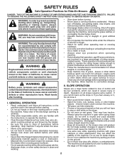
...operate the machine while under the influence of alcohol or drugs. • Watch for traffic when operating near rotating parts or under the machine. Operate only at all parts to come to protect themselves and others from serious injury. • Follow the manufacturer's recommendation for Ride-On Mowers... wheel weights or counterweights. • Keep machine free of grass , leaves or other debris build-up which can touch hot exhaust / engine parts and burn. If the tires lose traction, disengage the blades and proceed slowly straight down a hill in severe injury or death. II. WARNING...
...operate the machine while under the influence of alcohol or drugs. • Watch for traffic when operating near rotating parts or under the machine. Operate only at all parts to come to protect themselves and others from serious injury. • Follow the manufacturer's recommendation for Ride-On Mowers... wheel weights or counterweights. • Keep machine free of grass , leaves or other debris build-up which can touch hot exhaust / engine parts and burn. If the tires lose traction, disengage the blades and proceed slowly straight down a hill in severe injury or death. II. WARNING...

Owners Manual
Page 3
... control. • Travel slowly and allow children to cool before operating. Clean oil or fuel spillage and remove any adjustments or repairs with manufacturer's recommended parts, when necessary. • Mower blades are explosive. • Extinguish all cigarettes, cigars, pipes, and other than the operator. • Be alert and turn machine off...
... control. • Travel slowly and allow children to cool before operating. Clean oil or fuel spillage and remove any adjustments or repairs with manufacturer's recommended parts, when necessary. • Mower blades are explosive. • Extinguish all cigarettes, cigars, pipes, and other than the operator. • Be alert and turn machine off...
Owners Manual
Page 4
...on your purchase of the California Public Resources Code). TABLE OF CONTENTS SAFETY RULES 2-3 PRODUCT SPECIFICATIONS 4 CUSTOMER RESPONSIBILITIES 4 UNASSEMBLED PARTS 5 ASSEMBLY 6-9 OPERATION 10-16 MAINTENANCE SCHEDULE 17 MAINTENANCE 17-20 SERVICE AND ADJUSTMENTS 21-25 STORAGE 26 TROUBLESHOOTING 27-28 REPAIR... PARTS 29-42 4 It has been designed, engineered and manufactured to service or repair this tractor. CUSTOMER RESPONSIBILITIES • ...
...on your purchase of the California Public Resources Code). TABLE OF CONTENTS SAFETY RULES 2-3 PRODUCT SPECIFICATIONS 4 CUSTOMER RESPONSIBILITIES 4 UNASSEMBLED PARTS 5 ASSEMBLY 6-9 OPERATION 10-16 MAINTENANCE SCHEDULE 17 MAINTENANCE 17-20 SERVICE AND ADJUSTMENTS 21-25 STORAGE 26 TROUBLESHOOTING 27-28 REPAIR... PARTS 29-42 4 It has been designed, engineered and manufactured to service or repair this tractor. CUSTOMER RESPONSIBILITIES • ...

Owners Manual
Page 5
Washer (1) Shoulder Bolt (1) 3/8-16 Locknut (1) Wheel Mower (5) 1-3/16 O.D. Washers (1) Small Retainer Springs (2) Rear Lift Link Assemblies If Equipped (1) 3/4 O.D. UNASSEMBLED PARTS Mower Front Wheel (1) 1-1/4 O.D. Washers (1) Front (5) Large Lift Link Retainer Springs Assembly (1) Small (1) Anti- Retainer Sway Bar Springs Keys (2) Keys (1) Oil Drain Tube For Future Use Slope Sheet 5
Washer (1) Shoulder Bolt (1) 3/8-16 Locknut (1) Wheel Mower (5) 1-3/16 O.D. Washers (1) Small Retainer Springs (2) Rear Lift Link Assemblies If Equipped (1) 3/4 O.D. UNASSEMBLED PARTS Mower Front Wheel (1) 1-1/4 O.D. Washers (1) Front (5) Large Lift Link Retainer Springs Assembly (1) Small (1) Anti- Retainer Sway Bar Springs Keys (2) Keys (1) Oil Drain Tube For Future Use Slope Sheet 5
Owners Manual
Page 6
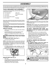
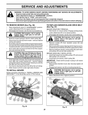
...Pliers (1) 3/4" socket w/drive ratchet (1) 9/16" wrench Flashlight When right or left hand is located between terminals) charge battery for any additional loose parts or cartons and remove. TO INSTALL MOWER AND DRIVE BELT (See Figs. 3 - 15) 1. Ensure parking brake will make assembly easier. Have... a tight grip on all accessible loose parts and parts cartons from clutch/brake pedal, then release parking brake lever. Pedal should remain in lowest position. TO REMOVE TRACTOR FROM CARTON UNPACK ...
...Pliers (1) 3/4" socket w/drive ratchet (1) 9/16" wrench Flashlight When right or left hand is located between terminals) charge battery for any additional loose parts or cartons and remove. TO INSTALL MOWER AND DRIVE BELT (See Figs. 3 - 15) 1. Ensure parking brake will make assembly easier. Have... a tight grip on all accessible loose parts and parts cartons from clutch/brake pedal, then release parking brake lever. Pedal should remain in lowest position. TO REMOVE TRACTOR FROM CARTON UNPACK ...
Owners Manual
Page 9
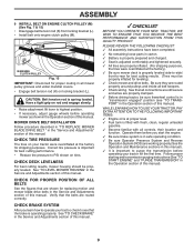
... operating your tractor for proper routing in this manual. PLEASE REVIEW THE FOLLOWING CHECKLIST: ✓ All assembly instructions have been completed. ✓ No remaining loose parts in the Operation section of this manual. Follow proper starting and transmission purging instructions (See "TO START ENGINE" and "PURGE TRANSMISSION" in the Service and...
... operating your tractor for proper routing in this manual. PLEASE REVIEW THE FOLLOWING CHECKLIST: ✓ All assembly instructions have been completed. ✓ No remaining loose parts in the Operation section of this manual. Follow proper starting and transmission purging instructions (See "TO START ENGINE" and "PURGE TRANSMISSION" in the Service and...
Owners Manual
Page 18
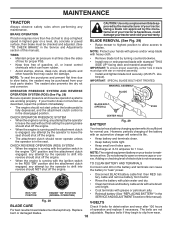
... BLADE CARE Check V-belts for 1 hour. However, periodic charging of the battery with heavy cloth. • Remove blade bolt by the manufacturer of your local parts dealer. BRAKE OPERATION If tractor requires more than five (5) feet to stop at 6-10 amperes for deterioration and wear after 100 hours For best results...
... BLADE CARE Check V-belts for 1 hour. However, periodic charging of the battery with heavy cloth. • Remove blade bolt by the manufacturer of your local parts dealer. BRAKE OPERATION If tractor requires more than five (5) feet to stop at 6-10 amperes for deterioration and wear after 100 hours For best results...
Owners Manual
Page 20
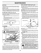
Thread the nozzle adapter (packaged with automotive type wax. of all pinch points and movable parts (See Fig. 34) CLUTCH/BRAKE PEDAL CLEAN TOP SIDE IMPORTANT: Tug hose ensuring connection is secure. 5. Fig. 35 • Clean debris from tractor and mower. ..., finish, etc. Move the tractor's attachment clutch control to keep water out. MAINTENANCE MUFFLER Inspect and replace corroded muffler and spark arrester (if equipped) as part of its surface as it could expose you or others to We do not recommend using mower again. • Plug any spilled gasoline. Turn the...
Thread the nozzle adapter (packaged with automotive type wax. of all pinch points and movable parts (See Fig. 34) CLUTCH/BRAKE PEDAL CLEAN TOP SIDE IMPORTANT: Tug hose ensuring connection is secure. 5. Fig. 35 • Clean debris from tractor and mower. ..., finish, etc. Move the tractor's attachment clutch control to keep water out. MAINTENANCE MUFFLER Inspect and replace corroded muffler and spark arrester (if equipped) as part of its surface as it could expose you or others to We do not recommend using mower again. • Plug any spilled gasoline. Turn the...
Owners Manual
Page 21
... tension rod is spring loaded. remove retainer springs and washers. • Go to "STOP" and remove key. • Make sure the blades and all moving parts have accumulated around mandrels and entire upper deck surface. • Remove belt from electric clutch pulley (M), both mandrel pulleys (R) and all screws. • Engage belt...
... tension rod is spring loaded. remove retainer springs and washers. • Go to "STOP" and remove key. • Make sure the blades and all moving parts have accumulated around mandrels and entire upper deck surface. • Remove belt from electric clutch pulley (M), both mandrel pulleys (R) and all screws. • Engage belt...
Owners Manual
Page 23
..., over cooling fan blades (F). 7. Pull belt slack toward front of tractor. Slide belt toward rear of tractor. 4. BELT REMOVAL - 1. Install new belt from your local parts dealer. Do not lose). • Repair tire and reassemble. • On rear wheels only: align grooves in and camber are not adjustable. Reinstall anti-rotation...
..., over cooling fan blades (F). 7. Pull belt slack toward front of tractor. Slide belt toward rear of tractor. 4. BELT REMOVAL - 1. Install new belt from your local parts dealer. Do not lose). • Repair tire and reassemble. • On rear wheels only: align grooves in and camber are not adjustable. Reinstall anti-rotation...
Owners Manual
Page 25
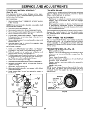
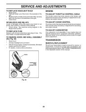
... has been preset at the factory and adjustment should not be necessary. TO REPLACE FUSE Replace with 20 amp automotive-type plug-in the Repair Parts section. If adjustment is not adjustable. See "PURGE TRANSMISSION" in front of this manual. The fuse holder is necessary, see engine manual. ENGINE TO ADJUST...
... has been preset at the factory and adjustment should not be necessary. TO REPLACE FUSE Replace with 20 amp automotive-type plug-in the Repair Parts section. If adjustment is not adjustable. See "PURGE TRANSMISSION" in front of this manual. The fuse holder is necessary, see engine manual. ENGINE TO ADJUST...
Owners Manual
Page 26
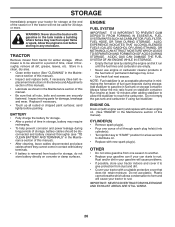
... periods of storage, battery cables should be disconnected and battery cleaned thoroughly (see "TO CLEAN BATTERY AND TERMINALS" in any enclosure. Inspect moving parts for a period of this manual). • Inspect and replace belts, if necessary (See belt re- NOTE: Fuel stabilizer is to be ...mix ratio found on concrete or damp surfaces. ENGINE FUEL SYSTEM IMPORTANT: IT IS IMPORTANT TO PREVENT GUM DEPOSITS FROM FORMING IN ESSENTIAL FUEL SYSTEM PARTS SUCH AS CARBURETOR, FUEL FILTER, FUEL HOSE, OR TANK DURING STORAGE. CYLINDER(S) • Remove spark plug(s). • Pour one season to...
... periods of storage, battery cables should be disconnected and battery cleaned thoroughly (see "TO CLEAN BATTERY AND TERMINALS" in any enclosure. Inspect moving parts for a period of this manual). • Inspect and replace belts, if necessary (See belt re- NOTE: Fuel stabilizer is to be ...mix ratio found on concrete or damp surfaces. ENGINE FUEL SYSTEM IMPORTANT: IT IS IMPORTANT TO PREVENT GUM DEPOSITS FROM FORMING IN ESSENTIAL FUEL SYSTEM PARTS SUCH AS CARBURETOR, FUEL FILTER, FUEL HOSE, OR TANK DURING STORAGE. CYLINDER(S) • Remove spark plug(s). • Pour one season to...

Owners Manual
Page 27
...tank and carburetor, refill tank with fresh, clean gas. 6. Contact an authorized service center/department. Bent blade mandrel. 3. Replace damaged parts. 27 Engine flooded. 4. Loose or damaged wiring. 9. See "TO START ENGINE" in "CHOKE" position. 2. Wait several minutes before...not turn over 1. Clean underside of adjustment. 1. Connect and tighten spark plug wire. 11. Engine valves out of fuel. 2. Tighten loose part(s). Bad spark plug. 5. Water in Service Adjustments section. 8. CORRECTION 1. Clean/replace air filter. 6. Check all wiring. 7. See "...
...tank and carburetor, refill tank with fresh, clean gas. 6. Contact an authorized service center/department. Bent blade mandrel. 3. Replace damaged parts. 27 Engine flooded. 4. Loose or damaged wiring. 9. See "TO START ENGINE" in "CHOKE" position. 2. Wait several minutes before...not turn over 1. Clean underside of adjustment. 1. Connect and tighten spark plug wire. 11. Engine valves out of fuel. 2. Tighten loose part(s). Bad spark plug. 5. Water in Service Adjustments section. 8. CORRECTION 1. Clean/replace air filter. 6. Check all wiring. 7. See "...
Owners Manual
Page 28
... mandrels. 1. of mower housing. 8. Battery will not rotate 1. Faulty regulator (if so equipped). 4. Replace battery. 2. Air trapped in "disengaged" position. 2. See "TO REMOVE WHEEL" in parts manual. 11. Reverse operation system (ROS) is not "ON" while mower or other attachment is shifted into reverse 1. Buildup of grass, leaves, trash under mower...
... mandrels. 1. of mower housing. 8. Battery will not rotate 1. Faulty regulator (if so equipped). 4. Replace battery. 2. Air trapped in "disengaged" position. 2. See "TO REMOVE WHEEL" in parts manual. 11. Reverse operation system (ROS) is not "ON" while mower or other attachment is shifted into reverse 1. Buildup of grass, leaves, trash under mower...

Owners Manual
Page 31
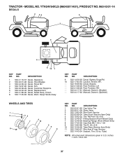
... 11 07-12 Switch Light / Reset 40 532 40 21-67 Harness Ign. inches 1 inch = 25.4 mm 31 NO. TRACTOR - YTH24V54XLS (96043011401), PRODUCT NO. 960 43 01-14 ELECTRICAL KEY PART NO. Dash 41 817 72 04-08 Screw Thd Cut 1/4-20 x 1/2 42 532 13 15-63 Cover, Terminal 43 532 19...
... 11 07-12 Switch Light / Reset 40 532 40 21-67 Harness Ign. inches 1 inch = 25.4 mm 31 NO. TRACTOR - YTH24V54XLS (96043011401), PRODUCT NO. 960 43 01-14 ELECTRICAL KEY PART NO. Dash 41 817 72 04-08 Screw Thd Cut 1/4-20 x 1/2 42 532 13 15-63 Cover, Terminal 43 532 19...

Owners Manual
Page 33
... 874 52 05-20 Bolt 5/16-18 x1-1/4 189 817 00 05-12 Screw 5/16-18 x 3/4 191 532 43 74-55 Insert Reflective RH KEY PART NO. inches 1 inch = 25.4 mm 33 NO. MODEL NO. DESCRIPTION 194 873 90 05-00 Nut Lock Hex Flange 5/16-18 199 532 41 34...-10 Clip Retainer 283 532 41 87-41 Console Deck Lift 284 532 41 78-87 Console Cntrl. NO. TRACTOR - YTH24V54XLS (96043011401), PRODUCT NO. 960 43 01-14 CHASSIS KEY PART NO. Pdl. 285 532 41 63-15 Console Insert RH 286 532 41 63-17 Console Insert LH 287 817 60...
... 874 52 05-20 Bolt 5/16-18 x1-1/4 189 817 00 05-12 Screw 5/16-18 x 3/4 191 532 43 74-55 Insert Reflective RH KEY PART NO. inches 1 inch = 25.4 mm 33 NO. MODEL NO. DESCRIPTION 194 873 90 05-00 Nut Lock Hex Flange 5/16-18 199 532 41 34...-10 Clip Retainer 283 532 41 87-41 Console Deck Lift 284 532 41 78-87 Console Cntrl. NO. TRACTOR - YTH24V54XLS (96043011401), PRODUCT NO. 960 43 01-14 CHASSIS KEY PART NO. Pdl. 285 532 41 63-15 Console Insert RH 286 532 41 63-17 Console Insert LH 287 817 60...

Owners Manual
Page 35
... Parking 170 532 41 34-30 Keeper Belt Centerspan 183 532 13 70-57 Spacer Split 184 532 40 31-18 Handle Parking Brake KEY PART NO. Pedal Control 211 532 12 01-83 Bearing Nylon 213 532 40 31-19 Knob Control Cruise 214 532 41 68-63 Pedal Forward... 76-93 Nut U CHNL 1/4-20 550DP .350 PNL 307 874 18 04-12 Screw 1/4-20 x 3/4 NOTE: All component dimensions given in U.S. MODEL NO. NO. NO. YTH24V54XLS (96043011401), PRODUCT NO. 960 43 01-14 DRIVE KEY...
... Parking 170 532 41 34-30 Keeper Belt Centerspan 183 532 13 70-57 Spacer Split 184 532 40 31-18 Handle Parking Brake KEY PART NO. Pedal Control 211 532 12 01-83 Bearing Nylon 213 532 40 31-19 Knob Control Cruise 214 532 41 68-63 Pedal Forward... 76-93 Nut U CHNL 1/4-20 550DP .350 PNL 307 874 18 04-12 Screw 1/4-20 x 3/4 NOTE: All component dimensions given in U.S. MODEL NO. NO. NO. YTH24V54XLS (96043011401), PRODUCT NO. 960 43 01-14 DRIVE KEY...

Owners Manual
Page 36
YTH24V54XLS (96043011401), PRODUCT NO. 960 43 01-14 ENGINE 116 21 1 14 20 22 92 18 91 15 37 28 37 29 90 45 69 92 12 86 11 41 42 85 9 87 62 71 70 2 SPARK ARRESTER KIT engine-tex_Kawa-2cyl_6 KEY PART NO. Engine KAWA Model No. MODEL NO. FR691V... 3/8-16 x 1 116 539 13 26-24 Knob Soft Touch NOTE: All component dimensions given in U.S. inches 1 inch = 25.4 mm For engine service and replacement parts, call the toll free number for your engine manufacturer listed below: Kawasaki 1-949-460-5688 36 DESCRIPTION 1 ------ TRACTOR - AS15 2 532 14 97-23 Muffler 9 ...
YTH24V54XLS (96043011401), PRODUCT NO. 960 43 01-14 ENGINE 116 21 1 14 20 22 92 18 91 15 37 28 37 29 90 45 69 92 12 86 11 41 42 85 9 87 62 71 70 2 SPARK ARRESTER KIT engine-tex_Kawa-2cyl_6 KEY PART NO. Engine KAWA Model No. MODEL NO. FR691V... 3/8-16 x 1 116 539 13 26-24 Knob Soft Touch NOTE: All component dimensions given in U.S. inches 1 inch = 25.4 mm For engine service and replacement parts, call the toll free number for your engine manufacturer listed below: Kawasaki 1-949-460-5688 36 DESCRIPTION 1 ------ TRACTOR - AS15 2 532 14 97-23 Muffler 9 ...
Owners Manual
Page 37
...NOTE: All component dimensions given in U.S. NO. TRACTOR - inches 1 inch = 25.4 mm 37 Keep Hands Away KEY PART NO. NO. DESCRIPTION 9 532 14 50-05 Decal, Battery Dnge/Poi 10 532 17 84-55 Caution Tension AR. ... - 532 44 17-62 Manual, Owner's (Spanish) WHEELS AND TIRES 1 2 11 3 4 7 10 6 wheel_art_1-tex 5 9 8 KEY PART NO. DESCRIPTION 1 532 05 91-92 Cap Valve Tire 2 532 06 51-39 Stem Valve 3 532 13 83-36 Rim Front Service 4 532... Service - - 532 14 43-34 Sealant, Tire (10 oz. YTH24V54XLS (96043011401), PRODUCT NO. 960 43 01-14 DECALS 2 56 2 3 1 9 4 8 10 7 KEY...
...NOTE: All component dimensions given in U.S. NO. TRACTOR - inches 1 inch = 25.4 mm 37 Keep Hands Away KEY PART NO. NO. DESCRIPTION 9 532 14 50-05 Decal, Battery Dnge/Poi 10 532 17 84-55 Caution Tension AR. ... - 532 44 17-62 Manual, Owner's (Spanish) WHEELS AND TIRES 1 2 11 3 4 7 10 6 wheel_art_1-tex 5 9 8 KEY PART NO. DESCRIPTION 1 532 05 91-92 Cap Valve Tire 2 532 06 51-39 Stem Valve 3 532 13 83-36 Rim Front Service 4 532... Service - - 532 14 43-34 Sealant, Tire (10 oz. YTH24V54XLS (96043011401), PRODUCT NO. 960 43 01-14 DECALS 2 56 2 3 1 9 4 8 10 7 KEY...

Owners Manual
Page 39
YTH24V54XLS (96043011401), PRODUCT NO. 960 43 01-14 MOWER DECK KEY PART NO. DESCRIPTION 1 532 42 41-29 Deck Weldment Mower 6 532 19 60-66 Cover Mandrel LH 7 532 19 71-81 Cover Mandrel RH 8 532 19 ... 50 872 11 06-16 Bolt Rdhd. Sqnk. 3/8-16 unc x 2 52 532 19 73-79 Pulley Idler 58 532 18 73-42 Baffle Right KEY PART NO. Mower Rear 190 532 19 65-39 Bolt Shoulder 192 532 19 84-68 Keeper Belt Idler 194 874 49 07-36 Bolt Hex...
YTH24V54XLS (96043011401), PRODUCT NO. 960 43 01-14 MOWER DECK KEY PART NO. DESCRIPTION 1 532 42 41-29 Deck Weldment Mower 6 532 19 60-66 Cover Mandrel LH 7 532 19 71-81 Cover Mandrel RH 8 532 19 ... 50 872 11 06-16 Bolt Rdhd. Sqnk. 3/8-16 unc x 2 52 532 19 73-79 Pulley Idler 58 532 18 73-42 Baffle Right KEY PART NO. Mower Rear 190 532 19 65-39 Bolt Shoulder 192 532 19 84-68 Keeper Belt Idler 194 874 49 07-36 Bolt Hex...


